EP0674145B1 - Rotary kiln wall equipped with a plurality of protrusions - Google Patents
Rotary kiln wall equipped with a plurality of protrusions Download PDFInfo
- Publication number
- EP0674145B1 EP0674145B1 EP95301443A EP95301443A EP0674145B1 EP 0674145 B1 EP0674145 B1 EP 0674145B1 EP 95301443 A EP95301443 A EP 95301443A EP 95301443 A EP95301443 A EP 95301443A EP 0674145 B1 EP0674145 B1 EP 0674145B1
- Authority
- EP
- European Patent Office
- Prior art keywords
- kiln
- powder
- protrusions
- blocks
- zone
- Prior art date
- Legal status (The legal status is an assumption and is not a legal conclusion. Google has not performed a legal analysis and makes no representation as to the accuracy of the status listed.)
- Expired - Lifetime
Links
Images

Classifications
-
- F—MECHANICAL ENGINEERING; LIGHTING; HEATING; WEAPONS; BLASTING
- F27—FURNACES; KILNS; OVENS; RETORTS
- F27B—FURNACES, KILNS, OVENS OR RETORTS IN GENERAL; OPEN SINTERING OR LIKE APPARATUS
- F27B7/00—Rotary-drum furnaces, i.e. horizontal or slightly inclined
-
- F—MECHANICAL ENGINEERING; LIGHTING; HEATING; WEAPONS; BLASTING
- F27—FURNACES; KILNS; OVENS; RETORTS
- F27B—FURNACES, KILNS, OVENS OR RETORTS IN GENERAL; OPEN SINTERING OR LIKE APPARATUS
- F27B7/00—Rotary-drum furnaces, i.e. horizontal or slightly inclined
- F27B7/20—Details, accessories or equipment specially adapted for rotary-drum furnaces
- F27B7/28—Arrangements of linings
-
- F—MECHANICAL ENGINEERING; LIGHTING; HEATING; WEAPONS; BLASTING
- F27—FURNACES; KILNS; OVENS; RETORTS
- F27B—FURNACES, KILNS, OVENS OR RETORTS IN GENERAL; OPEN SINTERING OR LIKE APPARATUS
- F27B7/00—Rotary-drum furnaces, i.e. horizontal or slightly inclined
- F27B7/14—Rotary-drum furnaces, i.e. horizontal or slightly inclined with means for agitating or moving the charge
- F27B7/16—Rotary-drum furnaces, i.e. horizontal or slightly inclined with means for agitating or moving the charge the means being fixed relatively to the drum, e.g. composite means
- F27B7/161—Rotary-drum furnaces, i.e. horizontal or slightly inclined with means for agitating or moving the charge the means being fixed relatively to the drum, e.g. composite means the means comprising projections jutting out from the wall
- F27B7/162—Rotary-drum furnaces, i.e. horizontal or slightly inclined with means for agitating or moving the charge the means being fixed relatively to the drum, e.g. composite means the means comprising projections jutting out from the wall the projections consisting of separate lifting elements, e.g. lifting shovels
Definitions
- the invention relates to kilns suitable for the calcination of powders and in particular to kilns known as directly heated rotary kilns.
- Directly heated rotary kilns employ a method of heat transfer in which solids are heated by direct contact with hot fluids, usually gases.
- hot gases are the products of combustion of a hydrocarbon fuel which are caused to flow over the solids in the rotary kiln whilst the kiln is rotated about its axis usually slightly inclined to the horizontal.
- the efficiency of heat transfer from the gas to the solid in these kilns is low because a relatively small part of the surface area of the solid is exposed to the hot gases.
- the efficiency can be improved by equipping the internal wall of the kiln with flights which lift and shower the solids through the gas stream as it passes through the kiln.
- the solid being calcined has a small particle size, for example when the solid is a pigment such as titanium dioxide, showering of the solid causes entrainment in the gas stream and significant losses unless the kiln is also equipped with a means for removal of the solids from the emerging gas stream.
- Kilns having protrusions on the inner wall which are generally in the shape of a plough and which are designed to turn over the soldis while the kiln rotates are known from, for example DE 400 236, FR 1 304 367 and US 1 544 504.
- the document US 1544504 discloses protrusions in form of a prism.
- An object of the current invention is to provide a kiln which has an improved heat transfer efficiency compared to known kilns and in which the loss of solids by entrainment is within acceptable limits.
- a kiln for calcination of a powder comprises a directly heated rotary kiln in which at least a part of the inner circumferential wall of the kiln is equipped with a plurality of protrusions, said protrusions having a triangular prismatic shape and being arranged within the kiln in such a manner that one triangular face of the prism is parallel to the inner circumferential wall and an edge formed by the intersection of two parallelogrammatic faces is the first part of the protrusion to emerge from a bed of powder within the kiln when the kiln is rotated in use, said triangular face of the prismatic protrusion being an isosceles triangle in which the equal angles are greater than the angle of repose of a powder for which the kiln is designed and said powder is substantially not lifted by the protrusions as a result of rotation of the kiln during use.
- the surface area ofthe inner wall ofthe kiln according to the invention is greater than the surface area of the inner wall of a conventional kiln of similar overall dimensions but in which the inner wall has a smooth surface.
- the inner wall In normal operation only a portion of the inner wall is in direct contact with the powder which is being calcined while the remaining portion of the inner wall is usually in contact with the hot gases. The wall area in contact with the gases is thereby heated and, after rotation of the kiln, comes into contact with the powder.
- Heat can then be transferred to the powder and, because of the increased surface area of the wall of the kiln of the invention compared to conventional kilns and also because of movement induced in the powder bed by the protrusions, this heat transfer process is more efficient than in known kilns.
- the protrusions also tend to produce turbulence in the gas stream which assists heat transfer to the inner wall and to the powder surface.
- the efficiency of heat transfer by means of the protrusions can be improved by ensuring that a bed of powder is present in the kiln during operation. Preferably this bed has a depth which ensures that the majority of the protrusions become totally immersed in the bed during some part of each revolution.
- the residence time in selected parts of the kiln can be controlled if a relatively deep bed of powder is formed by restricting the diameter of the kiln in one or more zones along the length of the kiln.
- a particularly preferred kiln according to the invention is equipped with protrusions as hereinbefore described and with zones of restricted diameter.
- one zone of restricted diameter will be close to the discharge end of the kiln but additional restrictions positioned in several zones along the length of the kiln provide a usefully deep bed of powder in a large proportion of the length of the kiln.
- These restrictions can be provided in any convenient way such as the inclusion of annular walls or dams within the kiln but preferably the kiln is restricted in such a manner that there is a free flow of the powder over the restriction.
- the protrusions can be fitted to the kiln by any convenient means.
- annular rings equipped with protrusions can be inserted into a kiln shell or a monolithic liner equipped with protrusions can be fitted within the kiln.
- rotary kilns are frequently lined with refractory bricks or blocks and a particularly convenient means of providing a kiln with the protrusions according to the invention comprises lining some or all of the kiln with refractory blocks, each block being equipped with one or more protrusions.
- a kiln is lined with a proportion of smooth-faced blocks and with a proportion of blocks equipped with one or more protrusions so as to form zones in which the inner wall of the kiln is smooth and zones in which protrusions are present. If desired, a zone can be lined with a mixture of smooth-faced blocks and blocks with protrusions.
- the proportion of the kiln wall which is equipped with protrusions depends, to some extent, on the process for which the kiln is designed.
- a relatively wet filter cake or paste is fed to a rotary kiln for drying and/or heat treatment and the presence of protrusions in the kiln at the end at which this material is introduced will normally lead to build-up of solid on the inner wall of the kiln. Therefore the inner wall at this end of the kiln is usually smooth. After initial loss of moisture the powder becomes more free-flowing and, in the zone where the powder is free-flowing, heat transfer by means of the protrusions is particularly efficient.
- the kiln is normally equipped with protrusions in the zone or zones in which the powder is free flowing when the kiln is in use.
- Some calcination processes for example in the preparation of titanium dioxide pigments, involve a period of residence in the kiln at a high temperature during which physical or chemical changes occur whilst heat is transferred from the gases to the powder (for example, in the conversion of anatase titanium dioxide to rutile titanium dioxide).
- a kiln designed for such a process is equipped with a smooth inner wall in the zone where the powder is maintained at this high temperature.
- a typical kiln according to the invention and intended for use in the calcination of titanium dioxide for production of pigments is equipped with a smooth inner wall in the zone where damp filter cake is introduced and extending up to about 65% of the length of the kiln measured from the end of kiln at which material is charged and in a zone extending up 10% of the length of the kiln measured from the end of the kiln at which dry titanium dioxide is discharged.
- the inner wall between these two zones is equipped with protrusions and, typically, from 20 to 30 % of the length of the kiln is so equipped.
- the shape and size of the protrusions governs, to some extent, the number of protrusions provided per unit area. However, the space between neighbouring protrusions must be such that the powder is not lifted as a result of bridging of the powder in the space between protrusions.
- the kiln according to the invention is suitable for use in a number of processes in which a solid is heated to remove water or to bring about a chemical or physical change. It can be used, for example, for roasting crushed ores, for chloridising silver ores, for the production of barium sulphide from barium sulphate, for the production of vermiculite and for drying a number of inorganic solids such as alumina, gypsum, clay and titanium dioxide. It is particularly useful in the preparation of titanium dioxide pigments in which a filter cake of hydrated titanium oxide precipitated from a titanium sulphate solution is dried and, usually, converted to the rutile crystal form by calcination in a rotary kiln.
- the main body 1 of the block is constructed from a refractory material such as is used in dense medium alumina firebricks and has a shape such that a number of the blocks can be formed into an annulus.
- the shape of the block is such that an appropriate number of blocks form a self-supporting arch although normally the blocks are also cemented into place within a metal shell of the rotary kiln.
- the block is equipped with a prismatic protrusion 2 and an assembly of the blocks of Figure 1 within a kiln provides a kiln with a plurality of protrusions according to the invention.
- the arrangement of blocks within the kiln is shown schematically in Figure 2.
- the direction of rotation of the kiln 11 is indicated by the arrow in Figure 2 and it can be seen that the blocks are arranged so that edge 3 of the prismatic protrusion (hereinafter called the leading edge) is the first part of the protrusion to emerge from the bed of powder lying on the bottom of the kiln as the kiln is rotated.
- edge 3 of the prismatic protrusion hereinafter called the leading edge
- the prismatic protrusion 2 and in particular the triangular surface 4 is shaped such that the powder is not retained on the surfaces of the protrusion after the protrusion emerges from the powder bed during rotation of the furnace.
- the triangular surface 4 is an isosceles triangle as shown, and the angles ⁇ of the triangle not adjacent to the leading edge are greater than the angle of repose of the powder for which the kiln is to be used.
- the height 5 of the prismatic protrusion is such that the triangular surface 4 is completely covered with powder during a part of each revolution of the kiln.
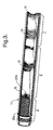
- Figure 3 illustrates a kiln 11 equipped with blocks as illustrated in Figure 1 and also three zones in which the diameter of the kiln 11 has been restricted by fitting blocks in the form of a dam 31.
- the kiln is constructed from a substantially cylindrical steel shell 12 in which some smooth-faced blocks 32a and some blocks 32b fitted with protrusions as illustrated in Figure 1 are annularly arranged and fixed with refractory cement.
- the dams 31 are constructed by an appropriate arrangement of smooth-faced blocks.
- the kiln illustrated in Figure 3 is rotated about its axis at a slight inclination to the horizontal.
- the illustrated kiln is particularly suitable for calcination of hydrous titanium oxide in the preparation of titanium dioxide pigments.
- the hydrous titanium oxide charged is relatively wet and is initially dried in Zone A equipped with smooth-faced blocks.
- Zone B where the kiln wall is equipped with blocks having a prismatic protrusion, the titanium dioxide is finally dried and raised to a temperature at which conversion of the anatase crystal form to the rutile crystal form takes place.
- efficient heat transfer is particularly important.
- the hot titanium dioxide is held at the highest temperature in the kiln for a period whilst conversion of anatase to rutile occurs, largely in Zone C where the wall of the kiln is fitted with smooth-faced blocks.
- the kiln according to the invention provides more efficient heat transfer than has been possible with conventional kilns, thereby improving throughput or reducing energy consumption in comparison to a conventional kiln of similar dimensions. Since the protrusions do not lift the powder out of the bed to any substantial extent the losses associated with entrainment of solid in the hot gas stream are not increased as a result of this improved heat transfer efficiency.
Landscapes
- Engineering & Computer Science (AREA)
- Mechanical Engineering (AREA)
- General Engineering & Computer Science (AREA)
- Muffle Furnaces And Rotary Kilns (AREA)
- Crucibles And Fluidized-Bed Furnaces (AREA)
- Processing Of Solid Wastes (AREA)
- Feeding, Discharge, Calcimining, Fusing, And Gas-Generation Devices (AREA)
- Vertical, Hearth, Or Arc Furnaces (AREA)
- Inorganic Compounds Of Heavy Metals (AREA)
Description
Claims (11)
- A kiln for calcination of a powder comprising a directly heated rotary kiln (11), at least a part of the inner circumferential wall of the kiln (11) is equipped with a plurality of protrusions (2), said protrusions (2) having a triangular prismatic shape characterised in that the protrusions (2) are arranged within the kiln in such a manner that one triangular face (4) of the prism is parallel to the axis of the inner circumferential wall and an edge (3) formed by the intersection of two parallelogrammatic faces is the first part of the protrusion (2) to emerge from a bed of powder within the kiln (11) when the kiln (11) is rotated in use, said triangular face (4) of the prismatic protrusion (2) being an isosceles triangle in which the equal angles (a) are greater than the angle of repose of a powder for which the kiln (11) is designed and said powder is not substantially lifted by the protrusions (2) as a result of rotation of kiln (11) during use.
- A kiln according to claim 1 characterised in that the prismatic protrusion (2) has a height (5) such that the triangular face (4) is completely covered by powder during a part of each revolution of the kiln (11) when the kiln (11) is in use.
- A kiln according to any one of the preceding claims characterised in that the diameter of the kiln (11) is restricted in one or more zones (31) along its length.
- A kiln according to any one of the preceding claims characterised in that the kiln (11) is lined with refractory blocks (1) and at least some of the blocks (1) which form a lining are equipped with one or more protrusions (2).
- A kiln according to claim 4 characterised in that the refractory blocks (1) have a shape which enables a number of blocks (1) to be assembled into a self-supporting arch.
- A kiln according to any one of the preceding claims and designed to accept a wet filter cake as feed material characterised in that said kiln (11) is provided with a smooth inner wall in a first zone (A) where the feed material is introduced into the kiln (11) and with an inner wall equipped with protrusions in a second zone (B) where the feed material is free-flowing during use of the kiln (11).
- A kiln according to claim 6 characterised in that the inner wall is smooth in a third zone (C) through which the feed material passes after passing through the second zone (B) during operation of the kiln (11).
- A kiln according to claim 7 characterised in that the first zone (A) has a length up to 65 per cent of the length of the kiln (11), the second zone (B) has a length between 20 and 30 per cent of the length of the kiln (11) and the third zone (C) has a length up to 10 per cent of the length of the kiln (11).
- A refractory block (1) for use in a directly heated rotary kiln comprising a main body having a shape such that a number of blocks can be colocated to form an annulus, at least one prismatic protrusion (2) is located on one face of the main body said face having a protrusion (2) being the face which forms the inner surface of the annulus when blocks are formed into an annulus characterised in that said prismatic protrusion (2) being a triangular prism having a face (4) which is an isosceles triangle having equal angles (α) of a magnitude greater than the angle of repose of a powder with which the block is designed to be used.
- A method for calcining a powder comprising heating the powder in a directly heated rotary kiln (11), said kiln (11) has an inner circumferential wall at least a part of which is equipped with a plurality of protrusions (2), said protrusions (2) being a triangular prismatic shape characterised in that the protrusions are arranged within the kiln (11) in such a manner that one triangular face (4) of the prism is parallel to the axis of the inner circumferential wall and an edge (3) formed by the intersection of two parallelogrammatic faces is the first part of the protrusion (2) to emerge from a bed of powder within the kiln (11) when the kiln (11) is rotated in use, said triangular face (4) of the prismatic protrusion (2) being an isosceles triangle in which the equal angles (α) are greater than the angle of repose of a powder for which the kiln (11) is designed and said powder is not substantially lifted by the protrusions as the kiln (11) is rotated.
- A process according to claim 10 characterised in that the powder is hydrous titanium oxide.
Applications Claiming Priority (2)
| Application Number | Priority Date | Filing Date | Title |
|---|---|---|---|
| GB9405760 | 1994-03-23 | ||
| GB9405760A GB9405760D0 (en) | 1994-03-23 | 1994-03-23 | Improved kiln |
Publications (2)
| Publication Number | Publication Date |
|---|---|
| EP0674145A1 EP0674145A1 (en) | 1995-09-27 |
| EP0674145B1 true EP0674145B1 (en) | 1998-10-07 |
Family
ID=10752378
Family Applications (1)
| Application Number | Title | Priority Date | Filing Date |
|---|---|---|---|
| EP95301443A Expired - Lifetime EP0674145B1 (en) | 1994-03-23 | 1995-03-06 | Rotary kiln wall equipped with a plurality of protrusions |
Country Status (16)
| Country | Link |
|---|---|
| US (1) | US5623883A (en) |
| EP (1) | EP0674145B1 (en) |
| JP (1) | JPH07324871A (en) |
| KR (1) | KR950033391A (en) |
| CN (1) | CN1120654A (en) |
| AU (1) | AU689188B2 (en) |
| CA (1) | CA2143970A1 (en) |
| DE (1) | DE69505170T2 (en) |
| DK (1) | DK0674145T3 (en) |
| ES (1) | ES2122445T3 (en) |
| FI (1) | FI951349A7 (en) |
| GB (2) | GB9405760D0 (en) |
| NO (1) | NO951093L (en) |
| RU (1) | RU2134390C1 (en) |
| TW (1) | TW294774B (en) |
| ZA (1) | ZA952057B (en) |
Families Citing this family (7)
| Publication number | Priority date | Publication date | Assignee | Title |
|---|---|---|---|---|
| KR100312263B1 (en) * | 1998-08-11 | 2001-12-28 | 심문섭 | Pile drawing device |
| US6309211B1 (en) | 2000-06-13 | 2001-10-30 | Suedala Industries, Inc. | Port air conveying system for rotary kiln |
| CA2458935A1 (en) * | 2004-03-02 | 2005-09-02 | Premier Horticulture Ltee | Oven and expansion process for perlite and vermiculite |
| FR2944344B1 (en) * | 2009-04-10 | 2013-12-27 | Inst Francais Du Petrole | ROTATING OVEN FOR THERMAL TREATMENT OF SOLID MATERIALS |
| EP4053483A1 (en) | 2021-03-05 | 2022-09-07 | S.A. Lhoist Recherche et Développement | Rotary kiln and method for firing carbonaceous material, in particular limestone or dolomite |
| EP4053484A1 (en) | 2021-03-05 | 2022-09-07 | S.A. Lhoist Recherche et Développement | Rotary kiln and method for firing carbonaceous material, in particular limestone or dolomite |
| EP4053485A1 (en) * | 2021-03-05 | 2022-09-07 | S.A. Lhoist Recherche et Développement | Rotary kiln and method for firing carbonaceous material, in particular limestone or dolomite |
Family Cites Families (14)
| Publication number | Priority date | Publication date | Assignee | Title |
|---|---|---|---|---|
| GB203673A (en) * | 1922-09-08 | 1924-05-29 | Nils Winqvist | Improvements in rotating kilns for burning cement and the like |
| DE400236C (en) * | 1922-09-08 | 1924-08-14 | Nils Winqvist | Rotary kiln for burning cement u. like |
| US1544504A (en) * | 1923-10-30 | 1925-06-30 | Clifford J Tomlinson | Rotary kiln |
| GB395729A (en) * | 1932-01-21 | 1933-07-21 | Mikael Vogel Jorgensen | Improvements in and relating to rotary kilns |
| US2261403A (en) * | 1941-01-22 | 1941-11-04 | Allis Chalmers Mfg Co | Rotary kiln chain arrangement |
| GB959048A (en) * | 1960-11-22 | 1964-05-27 | American Cement Corp | Improvements in or relating to rotary kilns |
| FR1304367A (en) * | 1961-10-23 | 1962-09-21 | American Cement Corp | Rotary kiln |
| US3455099A (en) * | 1968-03-29 | 1969-07-15 | Textron Inc | Dead end |
| DE2115849A1 (en) * | 1971-04-01 | 1972-10-12 | Claudius Peters Ag, 2000 Hamburg | Rotary drum, in particular rotary drum furnace for waste incineration |
| US4136965A (en) * | 1978-03-31 | 1979-01-30 | Bethlehem Steel Corporation | Mixer block for use in rotary drums |
| FR2423740A1 (en) * | 1978-04-21 | 1979-11-16 | Origny Ciments | Thermal economiser for long cement kiln - includes helicoidal refractory steel castings or chains |
| DE3443933A1 (en) * | 1984-12-01 | 1986-06-05 | Klöckner-Humboldt-Deutz AG, 5000 Köln | Rotary tube, in particular rotary tubular kiln for burning cement |
| SU1695099A1 (en) * | 1986-07-04 | 1991-11-30 | Восточный научно-исследовательский и проектный институт огнеупорной промышленности | Article for fireproof masonry of thermal units |
| RU2037116C1 (en) * | 1991-07-04 | 1995-06-09 | Акционерное общество открытого типа "Челябинский металлургический комбинат" | Lining of rotary tubular furnace for burning of ore-lime mixture |
-
1994
- 1994-03-23 GB GB9405760A patent/GB9405760D0/en active Pending
-
1995
- 1995-03-06 EP EP95301443A patent/EP0674145B1/en not_active Expired - Lifetime
- 1995-03-06 DE DE69505170T patent/DE69505170T2/en not_active Expired - Fee Related
- 1995-03-06 ES ES95301443T patent/ES2122445T3/en not_active Expired - Lifetime
- 1995-03-06 DK DK95301443T patent/DK0674145T3/en active
- 1995-03-06 GB GB9504434A patent/GB2287781B/en not_active Expired - Fee Related
- 1995-03-06 AU AU13635/95A patent/AU689188B2/en not_active Ceased
- 1995-03-06 CA CA002143970A patent/CA2143970A1/en not_active Abandoned
- 1995-03-07 TW TW084102136A patent/TW294774B/zh active
- 1995-03-13 ZA ZA952057A patent/ZA952057B/en unknown
- 1995-03-20 US US08/406,618 patent/US5623883A/en not_active Expired - Fee Related
- 1995-03-22 JP JP7062472A patent/JPH07324871A/en active Pending
- 1995-03-22 NO NO951093A patent/NO951093L/en unknown
- 1995-03-22 FI FI951349A patent/FI951349A7/en unknown
- 1995-03-22 CN CN95104058A patent/CN1120654A/en active Pending
- 1995-03-22 RU RU95104374A patent/RU2134390C1/en active
- 1995-03-23 KR KR1019950006145A patent/KR950033391A/en not_active Withdrawn
Also Published As
| Publication number | Publication date |
|---|---|
| AU689188B2 (en) | 1998-03-26 |
| RU95104374A (en) | 1996-12-27 |
| DE69505170D1 (en) | 1998-11-12 |
| JPH07324871A (en) | 1995-12-12 |
| NO951093L (en) | 1995-09-25 |
| GB2287781A (en) | 1995-09-27 |
| GB9405760D0 (en) | 1994-05-11 |
| DK0674145T3 (en) | 1999-06-21 |
| ZA952057B (en) | 1995-12-11 |
| TW294774B (en) | 1997-01-01 |
| KR950033391A (en) | 1995-12-26 |
| FI951349L (en) | 1995-09-24 |
| FI951349A0 (en) | 1995-03-22 |
| FI951349A7 (en) | 1995-09-24 |
| US5623883A (en) | 1997-04-29 |
| GB2287781B (en) | 1998-03-11 |
| AU1363595A (en) | 1995-10-05 |
| CA2143970A1 (en) | 1995-09-24 |
| NO951093D0 (en) | 1995-03-22 |
| DE69505170T2 (en) | 1999-03-04 |
| GB9504434D0 (en) | 1995-04-26 |
| RU2134390C1 (en) | 1999-08-10 |
| EP0674145A1 (en) | 1995-09-27 |
| CN1120654A (en) | 1996-04-17 |
| ES2122445T3 (en) | 1998-12-16 |
Similar Documents
| Publication | Publication Date | Title |
|---|---|---|
| EP0004756B1 (en) | Rotary drum and method of mixing, drying, cooling, heating or calcining solid particles | |
| HU217704B (en) | Rotary kiln with a polygonal lining | |
| US5623883A (en) | Kiln for calcination of a powder | |
| US5702247A (en) | Kiln lining and method | |
| CN100366535C (en) | A method of calcining kaolin with a rotary calcining kiln and the rotary calcining kiln | |
| US5873714A (en) | Rotary kiln having a lining with a wave-shaped inner face | |
| US3383438A (en) | Calcination of clay | |
| EP0052431B1 (en) | Cement burning plant | |
| SU696256A1 (en) | Overfill heat exchanger | |
| PL118323B1 (en) | Rotary kiln for firing cement clinker | |
| US4420302A (en) | Method and apparatus for thermally treating pulverulent materials | |
| CN206875945U (en) | a rotary kiln | |
| US4676740A (en) | Heat exchange apparatus and process for rotary kilns | |
| US4624634A (en) | Method and arrangement for improving the heat economy in rotary kilns | |
| JP2002188892A (en) | Rotary furnace wall with steps | |
| US4420303A (en) | Method and apparatus for thermally treating pulverulent materials | |
| SU1179067A1 (en) | Heat-exchanging device of rotating furnace | |
| EP0052429B1 (en) | Method and apparatus for thermally treating pulverulent material | |
| SU1190167A1 (en) | Rotating furnace with heat exchange lining for alumina calcination | |
| SU537230A1 (en) | Rotary kiln for burning and reduction of iron ores | |
| Shelton | KILN BUILDER'S VIEW OF THE REFRACTORIES INDUSTRY | |
| SU792051A1 (en) | Rotary furnace ceramic heat exchanger | |
| CN113758271A (en) | Masonry method of rotary furnace refractory bricks | |
| RU1796850C (en) | Regenerative shaft kiln | |
| SU932167A1 (en) | Tubular rotary furnace |
Legal Events
| Date | Code | Title | Description |
|---|---|---|---|
| PUAI | Public reference made under article 153(3) epc to a published international application that has entered the european phase |
Free format text: ORIGINAL CODE: 0009012 |
|
| 17P | Request for examination filed |
Effective date: 19950714 |
|
| AK | Designated contracting states |
Kind code of ref document: A1 Designated state(s): BE DE DK ES FR IE IT LU NL PT SE |
|
| 17Q | First examination report despatched |
Effective date: 19970401 |
|
| GRAG | Despatch of communication of intention to grant |
Free format text: ORIGINAL CODE: EPIDOS AGRA |
|
| GRAG | Despatch of communication of intention to grant |
Free format text: ORIGINAL CODE: EPIDOS AGRA |
|
| GRAH | Despatch of communication of intention to grant a patent |
Free format text: ORIGINAL CODE: EPIDOS IGRA |
|
| GRAH | Despatch of communication of intention to grant a patent |
Free format text: ORIGINAL CODE: EPIDOS IGRA |
|
| GRAA | (expected) grant |
Free format text: ORIGINAL CODE: 0009210 |
|
| ITF | It: translation for a ep patent filed | ||
| AK | Designated contracting states |
Kind code of ref document: B1 Designated state(s): BE DE DK ES FR IE IT LU NL PT SE |
|
| REF | Corresponds to: |
Ref document number: 69505170 Country of ref document: DE Date of ref document: 19981112 |
|
| REG | Reference to a national code |
Ref country code: IE Ref legal event code: FG4D Ref country code: ES Ref legal event code: FG2A Ref document number: 2122445 Country of ref document: ES Kind code of ref document: T3 |
|
| REG | Reference to a national code |
Ref country code: PT Ref legal event code: SC4A Free format text: AVAILABILITY OF NATIONAL TRANSLATION Effective date: 19981008 |
|
| PGFP | Annual fee paid to national office [announced via postgrant information from national office to epo] |
Ref country code: FR Payment date: 19990208 Year of fee payment: 5 |
|
| PGFP | Annual fee paid to national office [announced via postgrant information from national office to epo] |
Ref country code: DK Payment date: 19990209 Year of fee payment: 5 |
|
| ET | Fr: translation filed | ||
| PGFP | Annual fee paid to national office [announced via postgrant information from national office to epo] |
Ref country code: SE Payment date: 19990216 Year of fee payment: 5 |
|
| PGFP | Annual fee paid to national office [announced via postgrant information from national office to epo] |
Ref country code: IE Payment date: 19990218 Year of fee payment: 5 |
|
| PGFP | Annual fee paid to national office [announced via postgrant information from national office to epo] |
Ref country code: NL Payment date: 19990224 Year of fee payment: 5 |
|
| PGFP | Annual fee paid to national office [announced via postgrant information from national office to epo] |
Ref country code: PT Payment date: 19990226 Year of fee payment: 5 Ref country code: DE Payment date: 19990226 Year of fee payment: 5 |
|
| PGFP | Annual fee paid to national office [announced via postgrant information from national office to epo] |
Ref country code: BE Payment date: 19990302 Year of fee payment: 5 |
|
| PGFP | Annual fee paid to national office [announced via postgrant information from national office to epo] |
Ref country code: LU Payment date: 19990309 Year of fee payment: 5 |
|
| PGFP | Annual fee paid to national office [announced via postgrant information from national office to epo] |
Ref country code: ES Payment date: 19990312 Year of fee payment: 5 |
|
| REG | Reference to a national code |
Ref country code: DK Ref legal event code: T3 |
|
| PLBE | No opposition filed within time limit |
Free format text: ORIGINAL CODE: 0009261 |
|
| STAA | Information on the status of an ep patent application or granted ep patent |
Free format text: STATUS: NO OPPOSITION FILED WITHIN TIME LIMIT |
|
| 26N | No opposition filed | ||
| PG25 | Lapsed in a contracting state [announced via postgrant information from national office to epo] |
Ref country code: LU Free format text: LAPSE BECAUSE OF NON-PAYMENT OF DUE FEES Effective date: 20000306 Ref country code: IE Free format text: LAPSE BECAUSE OF NON-PAYMENT OF DUE FEES Effective date: 20000306 Ref country code: DK Free format text: LAPSE BECAUSE OF NON-PAYMENT OF DUE FEES Effective date: 20000306 |
|
| PG25 | Lapsed in a contracting state [announced via postgrant information from national office to epo] |
Ref country code: SE Free format text: LAPSE BECAUSE OF NON-PAYMENT OF DUE FEES Effective date: 20000307 Ref country code: ES Free format text: LAPSE BECAUSE OF NON-PAYMENT OF DUE FEES Effective date: 20000307 |
|
| PG25 | Lapsed in a contracting state [announced via postgrant information from national office to epo] |
Ref country code: BE Free format text: LAPSE BECAUSE OF NON-PAYMENT OF DUE FEES Effective date: 20000331 |
|
| BERE | Be: lapsed |
Owner name: TIOXIDE GROUP SERVICES LTD Effective date: 20000331 |
|
| PG25 | Lapsed in a contracting state [announced via postgrant information from national office to epo] |
Ref country code: PT Free format text: LAPSE BECAUSE OF NON-PAYMENT OF DUE FEES Effective date: 20000930 |
|
| PG25 | Lapsed in a contracting state [announced via postgrant information from national office to epo] |
Ref country code: NL Free format text: LAPSE BECAUSE OF NON-PAYMENT OF DUE FEES Effective date: 20001001 |
|
| EUG | Se: european patent has lapsed |
Ref document number: 95301443.8 |
|
| REG | Reference to a national code |
Ref country code: DK Ref legal event code: EBP |
|
| PG25 | Lapsed in a contracting state [announced via postgrant information from national office to epo] |
Ref country code: FR Free format text: LAPSE BECAUSE OF NON-PAYMENT OF DUE FEES Effective date: 20001130 |
|
| NLV4 | Nl: lapsed or anulled due to non-payment of the annual fee |
Effective date: 20001001 |
|
| REG | Reference to a national code |
Ref country code: FR Ref legal event code: ST |
|
| PG25 | Lapsed in a contracting state [announced via postgrant information from national office to epo] |
Ref country code: DE Free format text: LAPSE BECAUSE OF NON-PAYMENT OF DUE FEES Effective date: 20010103 |
|
| REG | Reference to a national code |
Ref country code: PT Ref legal event code: MM4A Free format text: LAPSE DUE TO NON-PAYMENT OF FEES Effective date: 20000930 |
|
| REG | Reference to a national code |
Ref country code: IE Ref legal event code: MM4A |
|
| REG | Reference to a national code |
Ref country code: ES Ref legal event code: FD2A Effective date: 20010910 |
|
| PG25 | Lapsed in a contracting state [announced via postgrant information from national office to epo] |
Ref country code: IT Free format text: LAPSE BECAUSE OF NON-PAYMENT OF DUE FEES;WARNING: LAPSES OF ITALIAN PATENTS WITH EFFECTIVE DATE BEFORE 2007 MAY HAVE OCCURRED AT ANY TIME BEFORE 2007. THE CORRECT EFFECTIVE DATE MAY BE DIFFERENT FROM THE ONE RECORDED. Effective date: 20050306 |