EP0673819A1 - Device for reducing the aerodynamic drag of a cavity in a flow and a vehicle, particularly a railway vehicle, comprising such a device - Google Patents
Device for reducing the aerodynamic drag of a cavity in a flow and a vehicle, particularly a railway vehicle, comprising such a device Download PDFInfo
- Publication number
- EP0673819A1 EP0673819A1 EP95400624A EP95400624A EP0673819A1 EP 0673819 A1 EP0673819 A1 EP 0673819A1 EP 95400624 A EP95400624 A EP 95400624A EP 95400624 A EP95400624 A EP 95400624A EP 0673819 A1 EP0673819 A1 EP 0673819A1
- Authority
- EP
- European Patent Office
- Prior art keywords
- cavity
- vehicle
- strip
- aerodynamic drag
- flow
- Prior art date
- Legal status (The legal status is an assumption and is not a legal conclusion. Google has not performed a legal analysis and makes no representation as to the accuracy of the status listed.)
- Granted
Links
Images


Classifications
-
- B—PERFORMING OPERATIONS; TRANSPORTING
- B61—RAILWAYS
- B61D—BODY DETAILS OR KINDS OF RAILWAY VEHICLES
- B61D17/00—Construction details of vehicle bodies
- B61D17/02—Construction details of vehicle bodies reducing air resistance by modifying contour ; Constructional features for fast vehicles sustaining sudden variations of atmospheric pressure, e.g. when crossing in tunnels
-
- Y—GENERAL TAGGING OF NEW TECHNOLOGICAL DEVELOPMENTS; GENERAL TAGGING OF CROSS-SECTIONAL TECHNOLOGIES SPANNING OVER SEVERAL SECTIONS OF THE IPC; TECHNICAL SUBJECTS COVERED BY FORMER USPC CROSS-REFERENCE ART COLLECTIONS [XRACs] AND DIGESTS
- Y02—TECHNOLOGIES OR APPLICATIONS FOR MITIGATION OR ADAPTATION AGAINST CLIMATE CHANGE
- Y02T—CLIMATE CHANGE MITIGATION TECHNOLOGIES RELATED TO TRANSPORTATION
- Y02T30/00—Transportation of goods or passengers via railways, e.g. energy recovery or reducing air resistance
Definitions
- the present invention relates to devices making it possible to modify the aerodynamic profile of a vehicle, in particular rail, that is to say the devices modifying the resistance to advancement generated by cavities present on its external surface, and more particularly carries, on a device for reducing the aerodynamic drag of a cavity in a flow, as well as on a vehicle, in particular a rail vehicle, comprising such a device.
- Transport vehicles in particular rail vehicles, have requirements to reduce driving resistance to reduce the size of traction equipment and limit energy consumption.
- the exterior surface of a train presents various cavities, such as the caesuras between cars, the pantograph housings, the undercarriage bogie housings, which constitute as many obstacles to the advancement of the train and increase the noise level. .
- the document FR-A-805 960 describes a device for reducing the resistance to advancement due to cuts or other interruptions of the vehicles.
- the device of the state of the art consists of at least one deflecting surface disposed on the vehicle, at the right of the interruption, in particular at the end of wagons or other vehicles capable of being coupled.
- the deflecting surfaces are arranged in extension of the surface of the vehicle on which the relative air slides and in such a way that it regulates the flow of this relative air, which tends to penetrate into the interruption where it normally creates a zone of eddies.
- the deflecting surfaces are based on the outward deflection of the air streams. It emerges from this document that the deflecting surfaces act as deflectors and that they have no technical effect on the flow of air inside the cavities.
- Document BE-A-417 270 describes an equipment for the fairing of movable bodies comprising surfaces deviators coming from moving parts in position and articulated around axes of oscillation, so that they can take variable orientations and either reduce the resistance to advancement of the moving body, or on the contrary increase it.
- the deflecting surfaces are based on the lateral deflection of the air streams. It also appears from this document that the deflecting surfaces act as deflectors and that they have no technical effect on the flow of air inside the cavities.
- the value of the drag is minimal for a value of the ratio ⁇ close to 1.
- the value of the drag suddenly doubles when the ratio ⁇ is close to 2 and remains at roughly constant until the ratio a is equal to 10 and then slowly decreases when the ratio a is greater than 10.
- Another solution consists in approaching a case where the ratio a is equal to 1. This solution is also difficult to implement because this amounts to either reducing the width 1, which is generally imposed by games, or to increase the volume of the cavity, which is unfavorable to the interior arrangement of the vehicle.
- Document FR 91 13 510 of the applicant describes means making it possible to reduce the resistance to advancement generated by cavities comprising, for a cavity, at least one profile disposed close to the cavity but not opposite this cavity, the profile being maintained at a determined distance from the exterior surface of the train, this determined distance making it possible to reduce said resistance to advancement.
- This solution has the drawbacks that the profiles must be placed at a relatively large distance from the cavity and at a relatively large height from the wall. This solution involves problems of space and the exterior size of the vehicle.
- the aerodynamic drag reduction device of the invention does not require that the dimensions of the cavity be varied and that the size of the vehicle be significantly increased.
- the device for reducing the aerodynamic drag of a cavity in a flow is characterized by a strip arranged astride at least one of the edges of the cavity and on the corresponding wall of the corresponding vehicle and near the wall.
- the invention also relates to a vehicle, in particular a rail vehicle, comprising at least one device for reducing the aerodynamic drag of a cavity.
- the invention also relates to a vehicle comprising two devices for reducing the aerodynamic drag of a cavity arranged symmetrically on either side of the cavity, one upstream and the other downstream of the flow relative to to the cavity.
- FIG. 1, described above, shows a curve C1 representing, for a given width 1 of a cavity of the prior art, the different values of the aerodynamic drag T as a function of the values of the ratio ⁇ .
- FIG. 2 represents a top view of the device for reducing the aerodynamic drag of a cavity in a flow according to the invention.
- the cavity 1 is delimited by a first 2 and a second 3 wall of a vehicle 8 giving rise to a first 4 and a second 5 edge of the cavity.
- the letter 1 designates the width of the cavity 1 and the letter P its depth.
- the device for reducing the aerodynamic drag of a cavity 1 in a flow 6 comprises a strip 7 disposed upstream of the cavity 1, straddling at least one of the edges 4, 5 and on the corresponding wall 2, 3 of the corresponding vehicle 8, 9 and near said wall 2, 3.
- the strip 7 is preferably arranged parallel to the wall 2, 3 of the vehicle 8, 9.
- the invention consists of a selection from an infinite number of ratios between the different dimensions of the strip.
- Table 1 gives, for values of the ratio ⁇ greater than or equal to 2 and less than or equal to 20, the preferred optimal values of different ratios between different dimensions of the strip.
- the dimensions and the position of the strip can vary a little around the optimal values given above without, however, significantly degrading the gain made on the value of the drag due to the presence of the strip.
- Table 2 below gives the ranges of values of the various ratios between the dimensions of the strip, ranges of values for which the gain made on the value of the drag, due to the presence of the strip, does not degrade importantly.
- the strip placed upstream of the cavity reduces the speed fluctuations above the cavity. This means that the lamella reduces the shear stresses of the flow in this area, thereby reducing the amount of energy transmitted by the flow to the fluid present in the cavity.
- FIG. 3 shows a curve C2 representing, as a function of the values of the ratio ⁇ , the different values of the aerodynamic drag T when the cavity is equipped with the device for reducing the aerodynamic drag of the invention.
- the slats are permanently fixed to the exterior surface of the vehicle by means of known supports (not shown).
- the supports can themselves be fixed to the vehicles by riveting or by welding.
- the slats and their supports can be made of the same material as that used to make the vehicle bodies.
- two aerodynamic drag reduction devices of the invention can be arranged symmetrically on either side of the cavity, one upstream and the other downstream of the flow relative to the cavity.
- the invention also relates to a vehicle, in particular a rail vehicle, comprising such a device for reducing the aerodynamic drag of a cavity in a flow.
Abstract
Description
La présente invention concerne les dispositifs permettant de modifier le profil aérodynamique d'un véhicule, notamment ferroviaire, c'est à dire les dispositifs modifiant la résistance à l'avancement engendrée par des cavités présentes sur sa surface extérieure, et porte, plus particulièrement, sur un dispositif de réduction de la traînée aérodynamique d'une cavité dans un écoulement, ainsi que sur un véhicule, notamment ferroviaire, comprenant un tel dispositif.The present invention relates to devices making it possible to modify the aerodynamic profile of a vehicle, in particular rail, that is to say the devices modifying the resistance to advancement generated by cavities present on its external surface, and more particularly carries, on a device for reducing the aerodynamic drag of a cavity in a flow, as well as on a vehicle, in particular a rail vehicle, comprising such a device.
Les véhicules de transport, notamment les véhicules ferroviaires, ont des exigences de réduction de la résistance à l'avancement pour réduire le dimensionnement des équipements de traction et limiter la consommation d'énergie.Transport vehicles, in particular rail vehicles, have requirements to reduce driving resistance to reduce the size of traction equipment and limit energy consumption.
Ainsi, on recherche les profils les plus aérodynamiques possibles. Cependant, la surface extérieure d'un train présente différentes cavités, telles: les césures entre voitures, les logements de pantographes, les logements de bogie sous caisse, qui constituent autant d'obstacles à l'avancement du train et augmentent le niveau du bruit.Thus, we seek the most aerodynamic profiles possible. However, the exterior surface of a train presents various cavities, such as the caesuras between cars, the pantograph housings, the undercarriage bogie housings, which constitute as many obstacles to the advancement of the train and increase the noise level. .
A vitesse élevée, une part importante de la résistance à l'avancement est due à la traînée aérodynamique des véhicules.At high speed, a large part of the drag resistance is due to the aerodynamic drag of the vehicles.
Une part de cette traînée est due aux incidents de forme de la carène extérieure des véhicules, plus particulièrement aux cavités. Dans le cas d'un train ce sont les césures entre véhicules d'un même convoi et les cavités qui reçoivent les bogies qui modifient le plus le profil aérodynamique.Part of this drag is due to incidents in the shape of the outer hull of vehicles, more particularly to cavities. In the case of a train, it is the caesuras between vehicles of the same convoy and the cavities which receive the bogies which most modify the aerodynamic profile.
Un moyen connu de l'état de la technique permettant de résoudre ces problèmes consiste à placer des bavettes en caoutchouc entre les voitures, de manière à assurer la continuité aérodynamique. Un inconvénient de cette solution est qu'elle condamne l'accessibilité aux appareils. De plus, ces dispositifs sont peu fiables dans le temps et augmentent la durée des interventions des services d'entretien. Il en est de même pour le logements de bogies et de pantographes où des systèmes de carénage fixes ou mobiles viennent masquer les cavités. Ces carénages cachent les appareils au détriment de la sécurité.One known means of the prior art for solving these problems consists in placing rubber mud flaps between the cars, so as to ensure aerodynamic continuity. A disadvantage of this solution is that it condemns accessibility to devices. In addition, these devices are unreliable over time and increase the duration of maintenance service interventions. The same is true for the housing of bogies and pantographs where fixed or mobile fairing systems hide the cavities. These fairings hide the devices at the expense of security.
Les problèmes présentés par ce type de cavités ne sont donc pas résolus de manière satisfaisante.The problems presented by this type of cavity are therefore not satisfactorily resolved.
Le document FR-A-805 960 décrit un dispositif pour la diminution de la résistance à l'avancement, due aux césures ou autres interruptions des véhicules.The document FR-A-805 960 describes a device for reducing the resistance to advancement due to cuts or other interruptions of the vehicles.
Le dispositif de l'état de la technique consiste en au moins une surface déflectrice disposée sur le véhicule, au droit de l'interruption, en particulier à l'extrémité des wagons ou autres véhicules susceptibles d'être accouplés.The device of the state of the art consists of at least one deflecting surface disposed on the vehicle, at the right of the interruption, in particular at the end of wagons or other vehicles capable of being coupled.
Les surfaces déflectrices sont disposées en prolongement de la surface du véhicule sur laquelle glisse l'air relatif et de telle manière qu'elle régularise l'écoulement de cet air relatif, qui tend à pénétrer dans l'interruption où il crée normalement une zone de remous.The deflecting surfaces are arranged in extension of the surface of the vehicle on which the relative air slides and in such a way that it regulates the flow of this relative air, which tends to penetrate into the interruption where it normally creates a zone of eddies.
Ce document FR-A-805 960 de l'état de la technique enseigne que les surfaces déflectrices sont sensiblement placées dans le plan d'écoulement de l'air relatif, c'est-à-dire, en prolongement des parois du véhicule. Les surfaces déflectrices peuvent être placées un peu en retrait, mais elles ne doivent pas en principe faire saillie à l'extérieur de ces parois.This document FR-A-805 960 of the prior art teaches that the deflecting surfaces are substantially placed in the relative air flow plane, that is to say, in extension of the walls of the vehicle. The deflecting surfaces can be set back a little, but they should not in principle protrude outside these walls.
Comme enseigné par ce document, les surfaces déflectrices sont basées sur la déviation vers l'extérieur des filets d'air. Il ressort de ce document que les surfaces déflectrices agissent comme des déflecteurs et qu'elles n'ont aucun effet technique sur l'écoulement de l'air à l'intérieur des cavités.As taught by this document, the deflecting surfaces are based on the outward deflection of the air streams. It emerges from this document that the deflecting surfaces act as deflectors and that they have no technical effect on the flow of air inside the cavities.
Le document BE-A-417 270 décrit un équipement pour le carénage des corps mobiles comportant des surfaces déviatrices issues d'organes mobiles en position et articulés autour d'axes d'oscillation, de manière qu'ils puissent prendre des orientations variables et soit réduire la résistance à l'avancement du corps mobile, soit au contraire l'accroître.Document BE-A-417 270 describes an equipment for the fairing of movable bodies comprising surfaces deviators coming from moving parts in position and articulated around axes of oscillation, so that they can take variable orientations and either reduce the resistance to advancement of the moving body, or on the contrary increase it.
Comme enseigné par ce document, les surfaces déviatrices sont basées sur la déviation latérale des filets d'air. Il ressort également de ce document que les surfaces déviatrices agissent comme des déflecteurs et qu'elles n'ont aucun effet technique sur l'écoulement de l'air à l'intérieur des cavités.As taught by this document, the deflecting surfaces are based on the lateral deflection of the air streams. It also appears from this document that the deflecting surfaces act as deflectors and that they have no technical effect on the flow of air inside the cavities.
Il apparaît que les problèmes présentés par ce type de cavités ne sont pas résolus de manière satisfaisante pour les raisons données ci-après.It appears that the problems presented by this type of cavity are not satisfactorily resolved for the reasons given below.
Il est connu que la traînée aérodynamique d'une cavité dépend fortement du rapport α entre sa largeur 1 et sa profondeur P.It is known that the aerodynamic drag of a cavity strongly depends on the ratio α between its
Comme indiqué sur la figure 1, à largeur 1 donnée de la cavité, la valeur de la traînée est minimale pour une valeur du rapport α proche de 1. La valeur de la traînée double brutalement lorsque le rapport α est voisin de 2 et reste à peu près constante jusqu'à ce que le rapport a soit égal à 10 pour redescendre ensuite lentement lorsque le rapport a est supérieur à 10.As indicated in FIG. 1, at given
Il s'avère que les cavités de l'art antérieur, par exemple celles décrites dans les documents cités précédemment, ont un rapport α compris entre 2 et 10 et correspondent donc au cas le plus défavorable.It turns out that the cavities of the prior art, for example those described in the documents cited above, have a ratio α of between 2 and 10 and therefore correspond to the most unfavorable case.
Une solution difficile à mettre en oeuvre consiste à boucher les cavités.A difficult solution to implement is to plug the cavities.
Une autre solution consiste à se rapprocher d'un cas où le rapport a est égal à 1. Cette solution est également difficile à mettre en oeuvre du fait que cela revient soit à diminuer la largeur 1, qui est en général imposée par des jeux, soit à augmenter le volume de la cavité, ce qui est défavorable à l'aménagement intérieur du véhicule.Another solution consists in approaching a case where the ratio a is equal to 1. This solution is also difficult to implement because this amounts to either reducing the
Une autre solution est donnée dans le document FR 91 13 510 de la demanderesse.Another solution is given in document FR 91 13 510 of the applicant.
Le document FR 91 13 510 de la demanderesse décrit des moyens permettant de réduire la résistance à l'avancement engendrée par des cavités comprenant pour une cavité, au moins un profil disposé à proximité de la cavité mais pas en face de cette cavité, le profil étant maintenu à une distance déterminée de la surface extérieure du train, cette distance déterminée permettant de réduire ladite résistance à l'avancement.Document FR 91 13 510 of the applicant describes means making it possible to reduce the resistance to advancement generated by cavities comprising, for a cavity, at least one profile disposed close to the cavity but not opposite this cavity, the profile being maintained at a determined distance from the exterior surface of the train, this determined distance making it possible to reduce said resistance to advancement.
Cette solution a comme inconvénients que les profils doivent être disposés à une distance relativement importante de la cavité et à une hauteur relativement importante de la paroi. Cette solution implique des problèmes d'encombrement et de gabarit extérieur du véhicule.This solution has the drawbacks that the profiles must be placed at a relatively large distance from the cavity and at a relatively large height from the wall. This solution involves problems of space and the exterior size of the vehicle.
C'est le mérite de la demanderesse que de proposer un dispositif de réduction de la traînée aérodynamique d'une cavité dans un écoulement, prenant en compte les dimensions de la cavité, ainsi que le gabarit du véhicule.It is the merit of the applicant to propose a device for reducing the aerodynamic drag of a cavity in a flow, taking into account the dimensions of the cavity, as well as the size of the vehicle.
En d'autre termes, le dispositif de réduction de la traînée aérodynamique de l'invention n'impose pas que l'on fasse varier les dimensions de la cavité et que l'on augmente sensiblement le gabarit du véhicule.In other words, the aerodynamic drag reduction device of the invention does not require that the dimensions of the cavity be varied and that the size of the vehicle be significantly increased.
Conformément à l'invention, le dispositif de réduction de la traînée aérodynamique d'une cavité dans un écoulement se caractérise par une lamelle disposée à cheval sur au moins l'un des bords de la cavité et sur la paroi correspondante du véhicule correspondant et à proximité de la paroi.According to the invention, the device for reducing the aerodynamic drag of a cavity in a flow is characterized by a strip arranged astride at least one of the edges of the cavity and on the corresponding wall of the corresponding vehicle and near the wall.
L'invention a également pour objet un dispositif de réduction de la traînée aérodynamique satisfaisant à l'une au moins des caractéristiques suivantes:
- la lamelle est disposée parallèlement à la paroi du véhicule;
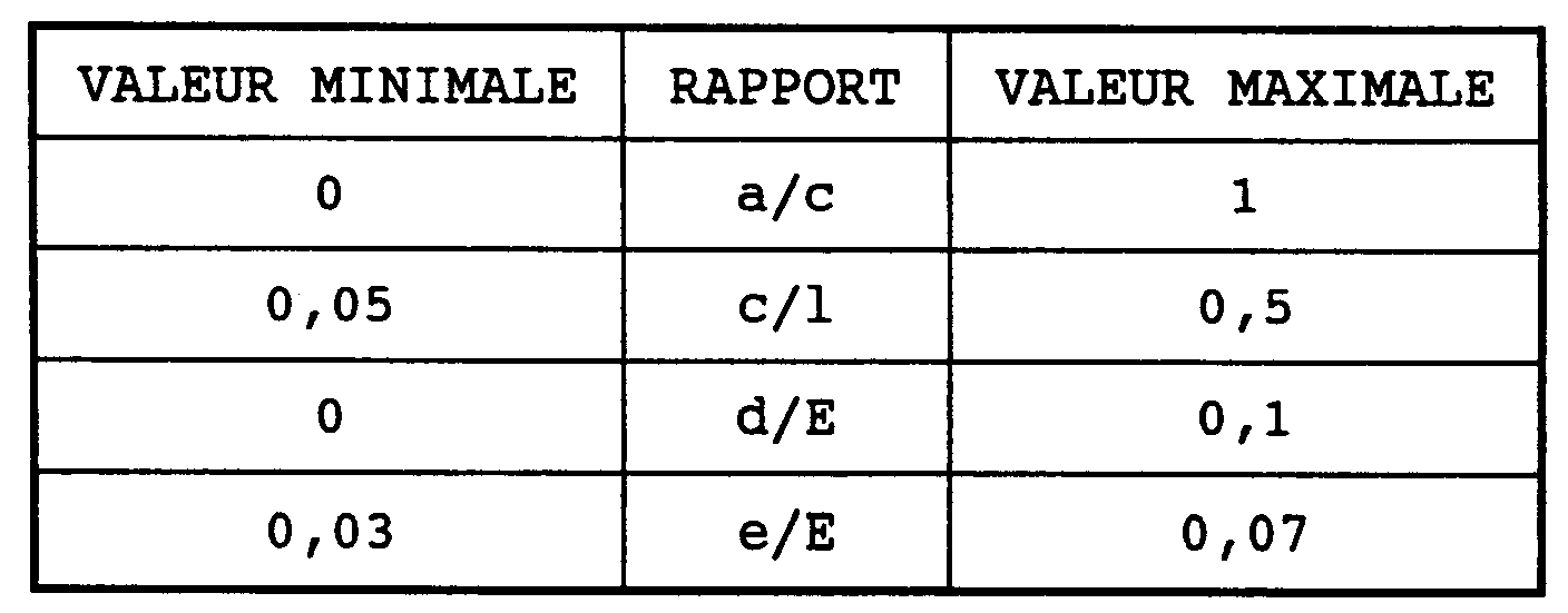
- la lamelle est telle que:
0 ≦ a/c ≦ 1
0,05 ≦ c/l ≦ 0,5
0 ≦ d/E ≦ 0,1
0,03 ≦ e/E ≦ 0,07- . la
lettre 1 désignant la largeur de la cavité, - . la lettre a désignant la longueur de la partie de la lamelle débordant sur la cavité,
- . la lettre c désignant la largeur de la lamelle,
- . la lettre d désignant l'épaisseur de la lamelle,
- . la lettre e désignant la distance entre la paroi du véhicule et la lamelle,
- . la lettre E désignant l'épaisseur de la couche limite de l'écoulement en amont de la cavité;
- . la
- la lamelle est telle que:
a/c est égal à 0,33;
c/l est égal à 0,21;
d/E est égal à 0,028; et
e/E est égal à 0,043;The subject of the invention is also a device for reducing aerodynamic drag satisfying at least one of the following characteristics:
- the strip is arranged parallel to the wall of the vehicle;
- the coverslip is such that:
0 ≦ a / c ≦ 1
0.05 ≦ c / l ≦ 0.5
0 ≦ d / E ≦ 0.1
0.03 ≦ e / E ≦ 0.07- . the
letter 1 designating the width of the cavity, - . the letter a designating the length of the part of the strip extending beyond the cavity,
- . the letter c designating the width of the slat,
- . the letter d designating the thickness of the strip,
- . the letter e designating the distance between the wall of the vehicle and the strip,
- . the letter E designating the thickness of the boundary layer of the flow upstream of the cavity;
- . the
- the coverslip is such that:
a / c is 0.33;
c / l is 0.21;
d / E is 0.028; and
e / E is 0.043;
L'invention porte également sur un véhicule, notamment ferroviaire, comprenant au moins un dispositif de réduction de la traînée aérodynamique d'une cavité.The invention also relates to a vehicle, in particular a rail vehicle, comprising at least one device for reducing the aerodynamic drag of a cavity.
L'invention porte également sur un véhicule comprenant deux dispositifs de réduction de la traînée aérodynamique d'une cavité disposés symétriquement de part et d'autre de la cavité, l'un en amont et l'autre en avale de l'écoulement par rapport à la cavité.The invention also relates to a vehicle comprising two devices for reducing the aerodynamic drag of a cavity arranged symmetrically on either side of the cavity, one upstream and the other downstream of the flow relative to to the cavity.
D'autres buts, caractéristiques et avantages de l'invention apparaîtront à la lecture de la description du dispositif de réduction de la traînée aérodynamique d'une cavité dans un écoulement, description faite en liaison avec les dessins joints dans lesquels:
- la figure 1 montre une courbe représentant, pour
une largeur 1 donnée de la cavité, les différentes valeurs de la traînée aérodynamique T en fonction des valeurs du rapport α - la figure 2 représente une vue en coupe horizontale du dispositif de réduction de la traînée aérodynamique d'une cavité dans un écoulement conforme à l'invention;
- la figure 3 montre deux courbes représentant la valeur de la traînée aérodynamique T en fonction des valeurs du rapport a lorsque, respectivement, la cavité n'est pas et est équipée du dispositif de réduction de la traînée aérodynamique de l'invention.
- FIG. 1 shows a curve representing, for a given
width 1 of the cavity, the different values of the aerodynamic drag T as a function of the values of the ratio α - 2 shows a horizontal sectional view of the device for reducing the aerodynamic drag of a cavity in a flow according to the invention;
- FIG. 3 shows two curves representing the value of the aerodynamic drag T as a function of the values of the ratio a when, respectively, the cavity is not and is equipped with the device for reducing the aerodynamic drag of the invention.
La figure 1, décrite ci-dessus, montre une courbe C1 représentant, pour une largeur 1 donnée d'une cavité de l'art antérieur, les différentes valeurs de la traînée aérodynamique T en fonction des valeurs du rapport α.FIG. 1, described above, shows a curve C1 representing, for a given
La figure 2 représente une vue de dessus du dispositif de réduction de la traînée aérodynamique d'une cavité dans un écoulement conforme à l'invention.FIG. 2 represents a top view of the device for reducing the aerodynamic drag of a cavity in a flow according to the invention.
La cavité 1 est délimitée par une première 2 et une seconde 3 paroi d'un véhicule 8 donnant naissance à un premier 4 et un second 5 bord de cavité.The
Sur la figure 2, la lettre 1 désigne la largeur de la cavité 1 et la lettre P sa profondeur.In FIG. 2, the
Conformément à l'invention, le dispositif de réduction de la traînée aérodynamique d'une cavité 1 dans un écoulement 6 comprend une lamelle 7 disposée en amont de la cavité 1, à cheval sur au moins l'un des bords 4, 5 et sur la paroi correspondante 2, 3 du véhicule correspondant 8, 9 et à proximité de ladite paroi 2, 3.According to the invention, the device for reducing the aerodynamic drag of a
La lamelle 7 est disposée, de préférence, parallèlement à la paroi 2, 3 du véhicule 8, 9.The strip 7 is preferably arranged parallel to the
Sur la figure 2 figurent également les lettres a, c, d et e:
- la lettre a désigne la longueur de la partie de la lamelle débordant sur la cavité;
- la lettre c désigne la largeur de la lamelle;
- la lettre d désigne l'épaisseur de la lamelle;
- la lettre e désigne la distance entre la paroi du véhicule et la lamelle;
- la lettre E désignant l'épaisseur de la couche limite de l'écoulement en amont de la cavité.
- the letter a designates the length of the part of the strip extending beyond the cavity;
- the letter c denotes the width of the slat;
- the letter d denotes the thickness of the strip;
- the letter e indicates the distance between the wall of the vehicle and the strip;
- the letter E designating the thickness of the boundary layer of the flow upstream of the cavity.
Le livre intitulé BOUNDARY LAYER THEORY, de Schlichting, édité en 1968, aux éditions Mc GRAY-HILL New-York, défini ce qu'est une couche limite de l'écoulement.The book entitled BOUNDARY LAYER THEORY, by Schlichting, published in 1968, published by Mc GRAY-HILL New-York, defines what a boundary layer of flow is.
L'invention consiste en une sélection parmi un nombre infini de rapport entre les différentes dimensions de la lamelle.The invention consists of a selection from an infinite number of ratios between the different dimensions of the strip.
Le tableau 1 ci-dessous donne, pour des valeurs du rapport α supérieures ou égales à 2 et inférieures ou égales à 20, les valeurs optimales préférées de différents rapport entre différentes dimensions de la lamelle.
Les dimensions et la position de la lamelle peuvent varier un peu autour des valeurs optimales données ci-dessus sans pour autant dégrader, de façon importante, le gain réalisé sur la valeur de la traînée du fait de la présence de la lamelle.The dimensions and the position of the strip can vary a little around the optimal values given above without, however, significantly degrading the gain made on the value of the drag due to the presence of the strip.
Le tableau 2 ci-dessous donne les gammes de valeurs des différents rapport entre les dimensions de la lamelle, gammes de valeurs pour lesquelles le gain réalisé sur la valeur de la traînée, du fait de la présence de la lamelle, ne se dégrade pas de façon importante.
![]()
![]()
Cette sélection des rapports entre dimensions de la lamelle a comme effet inattendu que le gain de traînée obtenu par le dispositif de réduction de la traînée aérodynamique de l'invention est d'environ 30 à 40 %, une fois prise en compte la traînée propre des lamelles.This selection of the ratios between dimensions of the strip has the unexpected effect that the gain in drag obtained by the aerodynamic drag reduction device of the invention is approximately 30 to 40%, once the proper drag of the blades is taken into account. slats.
Il a été observé que la lamelle diposée en amont de la cavité réduit les fluctuations de vitesse au dessus de la cavité. Ceci veut dire que la lamelle réduit les contraintes de cisaillement de l'écoulement dans cette zone, réduisant ainsi la quantité d'énergie transmise par l'écoulement au fluide présent dans la cavité.It has been observed that the strip placed upstream of the cavity reduces the speed fluctuations above the cavity. This means that the lamella reduces the shear stresses of the flow in this area, thereby reducing the amount of energy transmitted by the flow to the fluid present in the cavity.
Il apparait que pour des valeurs de a comprises entre 1,5 et 20, et surtout entre 2 et 10, cette quantité d'énergie est particulièrement élevée lorsque la cavité n'est pas munie du dispositif selon l'invention, alors qu'elle est comparativement faible pour des valeurs de a inférieures à 1,5. Ce qui précède explique pourquoi le dispositif selon l'invention est efficace quand α est compris entre 1,5 et 20.It appears that for values of a between 1.5 and 20, and especially between 2 and 10, this amount of energy is particularly high when the cavity is not provided with the device according to the invention, whereas it is comparatively small for values of a less than 1.5. The above explains why the device according to the invention is effective when α is between 1.5 and 20.
La traînée aérodynamique de la cavité ainsi équipée se rapproche donc de celle que la cavité aurait si le rapport a était égal à 1.The aerodynamic drag of the cavity thus equipped therefore approaches that which the cavity would have if the ratio a was equal to 1.
Des essais complémentaires ont montré que, de façon surprenante, lorsque le rapport α est égal à 1, le dispositif ne modifie pas la traînée de la cavité, une fois prise en compte la traînée propre des lamelles.Additional tests have shown that, surprisingly, when the ratio α is equal to 1, the device does not modify the drag of the cavity, once the proper drag of the strips is taken into account.
La figure 3 montre une courbe C2 représentant, en fonction des valeurs du rapport α, les différentes valeurs de la traînée aérodynamique T lorsque la cavité est équipée du dispositif de réduction de la traînée aérodynamique de l'invention. La courbe C1 représentée à la figure 1 et représentant, en fonction des valeurs du rapport a, les différentes valeurs de la traînée aérodynamique T lorsque la cavité n'est pas équipée du dispositif de réduction de la traînée aérodynamique de l'invention, est reprise sur cette figure 3.FIG. 3 shows a curve C2 representing, as a function of the values of the ratio α, the different values of the aerodynamic drag T when the cavity is equipped with the device for reducing the aerodynamic drag of the invention. The curve C1 shown in FIG. 1 and representing, as a function of the values of the ratio a, the different values of the aerodynamic drag T when the cavity is not equipped with the device for reducing the aerodynamic drag of the invention, is shown in this figure 3.
Les lamelles sont fixées de façon permanente à la surface extérieure du véhicule au moyen de supports connus (non représentés). Les supports peuvent être eux-mêmes fixés aux véhicules par rivetage ou par soudage.The slats are permanently fixed to the exterior surface of the vehicle by means of known supports (not shown). The supports can themselves be fixed to the vehicles by riveting or by welding.
Les lamelles et leurs supports peuvent être dans le même matériau que celui utilisé pour réaliser les caisses de véhicules.The slats and their supports can be made of the same material as that used to make the vehicle bodies.
Il est évident que pour utiliser la cavité dans les deux sens de la marche du train, deux dispositifs de réduction de la traînée aérodynamique de l'invention peuvent être disposés symétriquement de part et d'autre de la cavité, l'un en amont et l'autre en avale de l'écoulement par rapport à la cavité.It is obvious that in order to use the cavity in the two directions of travel of the train, two aerodynamic drag reduction devices of the invention can be arranged symmetrically on either side of the cavity, one upstream and the other downstream of the flow relative to the cavity.
L'invention porte également sur un véhicule, notamment ferroviaire, comprenant un tel dispositif de réduction de la traînée aérodynamique d'une cavité dans un écoulement.The invention also relates to a vehicle, in particular a rail vehicle, comprising such a device for reducing the aerodynamic drag of a cavity in a flow.
Claims (6)
a/c est égal à 0,33;
c/l est égal à 0,21;
d/E est égal à 0,028; et
e/E est égal à 0,043;Device according to claim 3; in which the lamella (7) is such that:
a / c is 0.33;
c / l is 0.21;
d / E is 0.028; and
e / E is 0.043;
Applications Claiming Priority (2)
| Application Number | Priority Date | Filing Date | Title |
|---|---|---|---|
| FR9403472A FR2717760B1 (en) | 1994-03-24 | 1994-03-24 | Device for reducing the aerodynamic drag of a cavity in a flow and vehicle, in particular rail, comprising such a device. |
| FR9403472 | 1994-03-24 |
Publications (2)
| Publication Number | Publication Date |
|---|---|
| EP0673819A1 true EP0673819A1 (en) | 1995-09-27 |
| EP0673819B1 EP0673819B1 (en) | 1999-08-25 |
Family
ID=9461392
Family Applications (1)
| Application Number | Title | Priority Date | Filing Date |
|---|---|---|---|
| EP95400624A Expired - Lifetime EP0673819B1 (en) | 1994-03-24 | 1995-03-21 | Device for reducing the aerodynamic drag of a cavity in a flow and a vehicle, particularly a railway vehicle, comprising such a device |
Country Status (8)
| Country | Link |
|---|---|
| US (1) | US5546865A (en) |
| EP (1) | EP0673819B1 (en) |
| JP (1) | JP3583497B2 (en) |
| KR (1) | KR100358023B1 (en) |
| CA (1) | CA2145237C (en) |
| DE (1) | DE69511603T2 (en) |
| ES (1) | ES2135668T3 (en) |
| FR (1) | FR2717760B1 (en) |
Cited By (4)
| Publication number | Priority date | Publication date | Assignee | Title |
|---|---|---|---|---|
| GB2514452A (en) * | 2013-03-15 | 2014-11-26 | Bae Systems Plc | Cavity acoustic tones suppression |
| DE202015106136U1 (en) | 2015-11-12 | 2015-11-19 | Deutsches Zentrum für Luft- und Raumfahrt e.V. | Transport container with aerodynamic flaps |
| US9463754B2 (en) | 2013-03-15 | 2016-10-11 | Bae Systems Plc | Cavity acoustic tones suppression |
| US9487289B2 (en) | 2013-03-15 | 2016-11-08 | Bae Systems Plc | Cavity acoustic tones suppression |
Families Citing this family (5)
| Publication number | Priority date | Publication date | Assignee | Title |
|---|---|---|---|---|
| JP2912178B2 (en) * | 1995-01-23 | 1999-06-28 | 株式会社日立製作所 | Railcar |
| DE19912144C1 (en) * | 1999-03-18 | 2000-11-02 | Daimler Chrysler Ag | Rail vehicle with a streamlined end part |
| US20110115254A1 (en) * | 2009-03-05 | 2011-05-19 | Joseph Skopic | Apparatus for reducing drag on vehicles with planar rear surfaces |
| DE102012205139A1 (en) | 2012-03-29 | 2013-10-02 | Havelländische Eisenbahn AG | Transport container, vehicle, traction unit, method for loading a transport container and method for transporting bulk material |
| AU2019444491B2 (en) | 2019-05-08 | 2023-05-11 | Deflect LLC | Deflector for vehicle |
Citations (7)
| Publication number | Priority date | Publication date | Assignee | Title |
|---|---|---|---|---|
| BE417270A (en) * | ||||
| FR805960A (en) * | 1935-08-24 | 1936-12-04 | Device for reducing resistance to advancement, due to breaks or other interruptions of vehicles | |
| US2182640A (en) * | 1937-06-21 | 1939-12-05 | Westinghouse Electric & Mfg Co | Electric locomotive structure |
| BE896717A (en) * | 1983-05-11 | 1983-09-01 | Gourmet Philippe | Deflector to reduce air resistance - is pivoted on vehicle roof and can be adjusted from inside cab |
| US4779915A (en) * | 1987-04-27 | 1988-10-25 | Straight Gary D | Air foil system |
| DE9003626U1 (en) * | 1990-03-28 | 1990-06-13 | Hiemeyer, August, 8190 Wolfratshausen, De | |
| EP0539904A1 (en) * | 1991-10-31 | 1993-05-05 | Gec Alsthom Sa | High speed train having means to change its aerodynamic profile |
Family Cites Families (3)
| Publication number | Priority date | Publication date | Assignee | Title |
|---|---|---|---|---|
| US2243906A (en) * | 1933-12-19 | 1941-06-03 | Huet Andre | Apparatus for shielding a body from fluid currents |
| AU522282B2 (en) * | 1977-06-17 | 1982-05-27 | Woolcock G E | Apparatus for reducing the wind resistance imposed on a primemover-trailer combination |
| DD160103A1 (en) * | 1981-03-27 | 1983-05-04 | Adolf Klier | AIR LINE DEVICE FOR REDUCING THE FLUID RESISTANCE OF HIGH-VOLTAGE VEHICLE VEHICLES |
-
1994
- 1994-03-24 FR FR9403472A patent/FR2717760B1/en not_active Expired - Fee Related
-
1995
- 1995-03-21 DE DE69511603T patent/DE69511603T2/en not_active Expired - Fee Related
- 1995-03-21 ES ES95400624T patent/ES2135668T3/en not_active Expired - Lifetime
- 1995-03-21 EP EP95400624A patent/EP0673819B1/en not_active Expired - Lifetime
- 1995-03-22 US US08/408,649 patent/US5546865A/en not_active Expired - Lifetime
- 1995-03-22 CA CA002145237A patent/CA2145237C/en not_active Expired - Fee Related
- 1995-03-24 KR KR1019950006312A patent/KR100358023B1/en not_active IP Right Cessation
- 1995-03-24 JP JP06606695A patent/JP3583497B2/en not_active Expired - Fee Related
Patent Citations (8)
| Publication number | Priority date | Publication date | Assignee | Title |
|---|---|---|---|---|
| BE417270A (en) * | ||||
| FR805960A (en) * | 1935-08-24 | 1936-12-04 | Device for reducing resistance to advancement, due to breaks or other interruptions of vehicles | |
| US2182640A (en) * | 1937-06-21 | 1939-12-05 | Westinghouse Electric & Mfg Co | Electric locomotive structure |
| BE896717A (en) * | 1983-05-11 | 1983-09-01 | Gourmet Philippe | Deflector to reduce air resistance - is pivoted on vehicle roof and can be adjusted from inside cab |
| US4779915A (en) * | 1987-04-27 | 1988-10-25 | Straight Gary D | Air foil system |
| DE9003626U1 (en) * | 1990-03-28 | 1990-06-13 | Hiemeyer, August, 8190 Wolfratshausen, De | |
| EP0539904A1 (en) * | 1991-10-31 | 1993-05-05 | Gec Alsthom Sa | High speed train having means to change its aerodynamic profile |
| FR2683199A1 (en) * | 1991-10-31 | 1993-05-07 | Alsthom Gec | HIGH SPEED TRAIN COMPRISING MEANS OF MODIFYING ITS AERODYNAMIC PROFILE. |
Cited By (8)
| Publication number | Priority date | Publication date | Assignee | Title |
|---|---|---|---|---|
| GB2514452A (en) * | 2013-03-15 | 2014-11-26 | Bae Systems Plc | Cavity acoustic tones suppression |
| GB2514452B (en) * | 2013-03-15 | 2016-06-08 | Bae Systems Plc | Cavity acoustic tones suppression |
| US9463754B2 (en) | 2013-03-15 | 2016-10-11 | Bae Systems Plc | Cavity acoustic tones suppression |
| US9487289B2 (en) | 2013-03-15 | 2016-11-08 | Bae Systems Plc | Cavity acoustic tones suppression |
| US9493233B2 (en) | 2013-03-15 | 2016-11-15 | Bae Systems Plc | Cavity acoustic tones suppression |
| DE202015106136U1 (en) | 2015-11-12 | 2015-11-19 | Deutsches Zentrum für Luft- und Raumfahrt e.V. | Transport container with aerodynamic flaps |
| DE102016120817A1 (en) | 2015-11-12 | 2017-05-18 | Deutsches Zentrum für Luft- und Raumfahrt e.V. | Transport container with aerodynamic flaps |
| DE102016120817B4 (en) | 2015-11-12 | 2018-12-27 | Deutsches Zentrum für Luft- und Raumfahrt e.V. | Transport container with aerodynamic flaps |
Also Published As
| Publication number | Publication date |
|---|---|
| FR2717760B1 (en) | 1996-04-26 |
| DE69511603D1 (en) | 1999-09-30 |
| ES2135668T3 (en) | 1999-11-01 |
| JPH07267081A (en) | 1995-10-17 |
| CA2145237C (en) | 2004-10-19 |
| KR100358023B1 (en) | 2003-01-24 |
| US5546865A (en) | 1996-08-20 |
| DE69511603T2 (en) | 2000-03-02 |
| CA2145237A1 (en) | 1995-09-25 |
| FR2717760A1 (en) | 1995-09-29 |
| EP0673819B1 (en) | 1999-08-25 |
| JP3583497B2 (en) | 2004-11-04 |
| KR950031742A (en) | 1995-12-20 |
Similar Documents
| Publication | Publication Date | Title |
|---|---|---|
| EP0673819A1 (en) | Device for reducing the aerodynamic drag of a cavity in a flow and a vehicle, particularly a railway vehicle, comprising such a device | |
| EP2296917B1 (en) | Directional tire tread provided with fitted incisions | |
| EP2450274A3 (en) | Landing gear noise attenuation | |
| EP3378723A1 (en) | Railway vehicle bogie comprising axles rigidly attached to the frame of the bogie | |
| FR3064584A1 (en) | INTEGRATED MOBILE DEFLECTOR GLASS ELEMENT | |
| EP3473513B1 (en) | Step for a railway vehicle, associated door system, railway vehicle and method | |
| EP2307617B1 (en) | Device for compensating expansion for a guide rail | |
| EP0418116A1 (en) | Metal reinforcement for strip or sealing joint, particularly for the automotive industry | |
| FR2841315A1 (en) | Kinematic transmission device comprises several cables and drive pinion rotated in one direction or another, cable arranged in pairs, first pair directly driven by pinion and second pair by mechanical connection | |
| CH631923A5 (en) | PNEUMATIC. | |
| FR2604661A1 (en) | FLUSHABLE MOBILE ICE SYSTEM, IN PARTICULAR FOR AUTOMOTIVE DOOR | |
| FR2557054A1 (en) | Device for the rolling and guidance of a funicular on rails | |
| EP0539904A1 (en) | High speed train having means to change its aerodynamic profile | |
| FR3102427A1 (en) | Retractable reversing camera in a movable spoiler | |
| EP4034272B1 (en) | Pulley with single-direction travel | |
| FR2848920A1 (en) | Automobile roof blind is wound on support comprising endless band mounted on two rollers one of which comprises band driving means | |
| FR2986775A1 (en) | MOUNTING STRUCTURE OF A DRIVING STATION OF A VEHICLE | |
| EP3521128B1 (en) | Modular railway body and railway vehicle of variable length | |
| FR2798341A1 (en) | Wiper for rear windscreen of a car comprises a wiper blade bent along a plane perpendicular to the windscreen's plan | |
| FR3074127B1 (en) | PALLET DOOR MODULE WITH A HIGH GUIDE SYSTEM | |
| EP1791707B1 (en) | Sun-visor for a motor vehicle | |
| EP1754651A2 (en) | Assembly of profiles of closed hollow section | |
| EP2922717B1 (en) | Motor vehicle roof air intake | |
| FR2488204A1 (en) | Articulation for railway vehicle bogie - has bearing rings between concentric tubes attached to longitudinal channels to allow tilting | |
| EP0660650B1 (en) | Printed circuit board having improved solder drainage pads |
Legal Events
| Date | Code | Title | Description |
|---|---|---|---|
| PUAI | Public reference made under article 153(3) epc to a published international application that has entered the european phase |
Free format text: ORIGINAL CODE: 0009012 |
|
| AK | Designated contracting states |
Kind code of ref document: A1 Designated state(s): DE ES FR IT |
|
| 17P | Request for examination filed |
Effective date: 19960123 |
|
| 17Q | First examination report despatched |
Effective date: 19971218 |
|
| GRAG | Despatch of communication of intention to grant |
Free format text: ORIGINAL CODE: EPIDOS AGRA |
|
| GRAG | Despatch of communication of intention to grant |
Free format text: ORIGINAL CODE: EPIDOS AGRA |
|
| GRAH | Despatch of communication of intention to grant a patent |
Free format text: ORIGINAL CODE: EPIDOS IGRA |
|
| GRAH | Despatch of communication of intention to grant a patent |
Free format text: ORIGINAL CODE: EPIDOS IGRA |
|
| GRAA | (expected) grant |
Free format text: ORIGINAL CODE: 0009210 |
|
| AK | Designated contracting states |
Kind code of ref document: B1 Designated state(s): DE ES FR IT |
|
| ITF | It: translation for a ep patent filed |
Owner name: JACOBACCI & PERANI S.P.A. |
|
| REF | Corresponds to: |
Ref document number: 69511603 Country of ref document: DE Date of ref document: 19990930 |
|
| REG | Reference to a national code |
Ref country code: ES Ref legal event code: FG2A Ref document number: 2135668 Country of ref document: ES Kind code of ref document: T3 |
|
| PLBE | No opposition filed within time limit |
Free format text: ORIGINAL CODE: 0009261 |
|
| STAA | Information on the status of an ep patent application or granted ep patent |
Free format text: STATUS: NO OPPOSITION FILED WITHIN TIME LIMIT |
|
| 26N | No opposition filed | ||
| PGFP | Annual fee paid to national office [announced via postgrant information from national office to epo] |
Ref country code: ES Payment date: 20090324 Year of fee payment: 15 |
|
| PGFP | Annual fee paid to national office [announced via postgrant information from national office to epo] |
Ref country code: IT Payment date: 20090325 Year of fee payment: 15 Ref country code: DE Payment date: 20090320 Year of fee payment: 15 |
|
| PGFP | Annual fee paid to national office [announced via postgrant information from national office to epo] |
Ref country code: FR Payment date: 20090312 Year of fee payment: 15 |
|
| REG | Reference to a national code |
Ref country code: FR Ref legal event code: ST Effective date: 20101130 |
|
| PG25 | Lapsed in a contracting state [announced via postgrant information from national office to epo] |
Ref country code: FR Free format text: LAPSE BECAUSE OF NON-PAYMENT OF DUE FEES Effective date: 20100331 |
|
| PG25 | Lapsed in a contracting state [announced via postgrant information from national office to epo] |
Ref country code: DE Free format text: LAPSE BECAUSE OF NON-PAYMENT OF DUE FEES Effective date: 20101001 |
|
| PG25 | Lapsed in a contracting state [announced via postgrant information from national office to epo] |
Ref country code: IT Free format text: LAPSE BECAUSE OF NON-PAYMENT OF DUE FEES Effective date: 20100321 |
|
| REG | Reference to a national code |
Ref country code: ES Ref legal event code: FD2A Effective date: 20110419 |
|
| PG25 | Lapsed in a contracting state [announced via postgrant information from national office to epo] |
Ref country code: ES Free format text: LAPSE BECAUSE OF NON-PAYMENT OF DUE FEES Effective date: 20110404 |
|
| PG25 | Lapsed in a contracting state [announced via postgrant information from national office to epo] |
Ref country code: ES Free format text: LAPSE BECAUSE OF NON-PAYMENT OF DUE FEES Effective date: 20100322 |