EP0671956B1 - Appareil et procede de test pour sterilisateur - Google Patents
Appareil et procede de test pour sterilisateur Download PDFInfo
- Publication number
- EP0671956B1 EP0671956B1 EP93911067A EP93911067A EP0671956B1 EP 0671956 B1 EP0671956 B1 EP 0671956B1 EP 93911067 A EP93911067 A EP 93911067A EP 93911067 A EP93911067 A EP 93911067A EP 0671956 B1 EP0671956 B1 EP 0671956B1
- Authority
- EP
- European Patent Office
- Prior art keywords
- signal
- steam
- chamber
- indicative
- generating
- Prior art date
- Legal status (The legal status is an assumption and is not a legal conclusion. Google has not performed a legal analysis and makes no representation as to the accuracy of the status listed.)
- Expired - Lifetime
Links
Images


Classifications
-
- A—HUMAN NECESSITIES
- A61—MEDICAL OR VETERINARY SCIENCE; HYGIENE
- A61L—METHODS OR APPARATUS FOR STERILISING MATERIALS OR OBJECTS IN GENERAL; DISINFECTION, STERILISATION OR DEODORISATION OF AIR; CHEMICAL ASPECTS OF BANDAGES, DRESSINGS, ABSORBENT PADS OR SURGICAL ARTICLES; MATERIALS FOR BANDAGES, DRESSINGS, ABSORBENT PADS OR SURGICAL ARTICLES
- A61L2/00—Methods or apparatus for disinfecting or sterilising materials or objects other than foodstuffs or contact lenses; Accessories therefor
- A61L2/26—Accessories or devices or components used for biocidal treatment
- A61L2/28—Devices for testing the effectiveness or completeness of sterilisation, e.g. indicators which change colour
Definitions
- the invention relates to sterilizers and, in particular, to a method and apparatus for improving the assurance of effective operation of sterilizers, especially those of the prevacuum type.
- a uniform color change (supported by a record showing a satisfactory time-temperature relationship in the chamber drain) indicated a satisfactory result and could be interpreted as showing rapid steam penetration, adequate air removal, and freedom from significant air leaks.
- Bowie and Dick type tests are typically run once a day and, if run and interpreted correctly, can determine only the condition of air leakage and can determine it only at that time.
- the sterilizer operations which are actually responsible for assuring the safety of patients are conducted under load conditions and cannot be monitored with accuracy with current technology.
- Joslyn disclosed a method and apparatus for detecting entrapped air in a steam sterilizer.
- the device is shown outside the steam chamber to enable quantitative measurement of the amount of air or other noncondensible gas at the chamber drain.
- the device is intended for use with a sterilizer of the type that employs steam to displace air. The device does not, however, eliminate the need for a Bowie and Dick test.
- Chamberlain and Cook monitor the temperature of the exhausted steam at the drain and the pressure within the chamber, and compare these to the steam table values to determine if all the air has been evacuated.
- the positioning of sensors within the chamber, especially by retrofitting, can, however, create further problem areas for future concern.
- Joslyn describes a small device for indicating air inside a sterilization chamber of the type used with steam or ethylene oxide.
- the device includes an upright tube holding an indicator strip and a heat sink. Air is said to pass into the tube where it interferes with the steam contacting the indicator strip.
- the present invention provides methods and apparatus for determining the effectiveness of air removal from a steam sterilizer and for monitoring the sterilization conditions therein.
- the apparatus provides a test device, a controller and a system which utilizes one or both.
- the methods achieve the objects of the invention in its broad as well as specific aspects.
- the test device comprises: a wall member defining an elongated test cavity having an opening at one end to permit entrance of ambient gases; a temperature sensor capable of generating a signal (T 1 ) indicative of the temperature at its location at an end of the test cavity opposite from said opening; and a heat sink located in said test cavity between said opening and said temperature sensor.
- the test device will comprise: means for sensing the temperature at a location within a sterilization chamber and generating a signal (T 1 ) indicative thereof; and radio transmission means for transmitting signal T 1 to a location outside of the sterilization chamber.
- storage means are provided for storing signal T 1 within said chamber.
- the controller in one of its preferred forms comprises: means for receiving a signal (T 1 ) indicative of the temperature at a predetermined location within the chamber of a steam sterilizer; means for generating a signal (T r ) indicative of a reference temperature, which can be either a preselected reference temperature such as the desired sterilization temperature or a calculated temperature such as the average of selected temperatures reported in the latest of a predetermined number of cycles of operation in either two modes (namely, (1) Bowie and Dick test or (2) operation under load); means for comparing signal T 1 to signal T r ; and means for generating a signal indicative of either a pass or fail condition based on the results of the comparison.
- the means for receiving the signal T 1 can comprise a radio receiver or connector means to electrically couple the controller to the test device.
- the system in one of its embodiments comprises: a test device capable of sensing the temperature at its location and generating a signal (T 1 ) indicative thereof; means for generating a signal (T r ) indicative of a reference temperature, as above; means for comparing signal T 1 to signal T r ; and means for generating a signal indicative of either a pass or fail condition based on the results of the comparison.
- the method of the invention in one of its forms comprises: placing a test device capable of sensing a temperature within the chamber of a sterilizer and generating a signal (T 1 ) indicative of the sensed temperature; generating a signal T 1 ; generating a signal T r indicative of a reference temperature; comparing signal T 1 to signal T r ; and generating a signal indicative of either a pass or fail condition based on the results of the comparison.
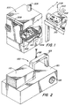
- Figure 1 illustrates a preferred system of the invention which includes a test unit 100 inside the chamber 202 of a sterilizer 200.
- the test unit is shown positioned near drain 204, for obtaining data and transmitting via radio frequency to controller 300 which is shown outside of the chamber 202.
- the system can operate by obtaining temperature data alone or in combination with pressure and/or dispersed liquid moisture data.
- the data can be transmitted from the chamber by radio to provide real time monitoring, or it can be stored within the test unit 100 for later later transmission to controller 300 such as through electrical connection, infra red data transmission, or other suitable means.
- a permanent archiveable record 302 can be generated by display means such as a thermal printer or a chart recorder. This enables accurate records to be kept, whether the system is operated in a mode to perform a Bowie and Dick type test (Bowie and Dick mode) or in a mode to monitor the operation of the sterilizer under load conditions (load mode).
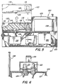
- FIG. 2 shows a preferred form of test device of the invention in greater detail, as do the partially cut away view of Figure 5 and the sectional view of Figure 6.
- the test unit 100 is seen to be comprised of two principal components, illustrated as a replaceable test module 110 and a data collection and transmission unit 120.
- data is transmitted via radio circuitry from transmission unit 120 via antenna 108 as will be described in greater detail below.
- means are also provided to store the data within the unit 100 for later processing. It is also possible to provide a test unit such as 100 which is not equipped with radio transmission means.
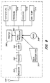
- FIG 7 corresponds to Figure 5 by showing the major components in block diagram form. Included are an array of sensors 121, namely temperature sensor 122, pressure sensor 124, moisture sensor 126, and box temperature sensor 128. Temperature sensor 122 is preferably a solid state temperature transducer, such as an Analog Devices (Maynard, MA) model AD 590 with a resolution of -17.5°C (0.5°F) and a measurement range of 125-141.1°C (257°-286°F).
- the pressure sensor 124 is preferably a pressure transducer as shown in Figures 5 and 6.
- the temperature sensor 122 and port 123 to the pressure sensor 124 are shown as component parts of replaceable test module 110.
- the moisture sensor 126 is desirably embedded within heat sink material 112 in the test module 110.
- the temperature sensor 128 will be embedded within or closely associated with the temperature-sensitive electronic components, such as multiplexer 130 within the transmission unit 120.
- the temperature sensor 128, can be similar to sensor 122 and is capable of generating a signal indicative of the temperature within the transmission unit 120 to warn of overheating.
- the temperature sensor 122 senses the temperature within test cavity 115 located at a position in the sterilizer, usually near the drain 204, where it would be most sensitive to the presence of air. All of the test devices of the present invention have the capability of obtaining temperature data by sensing the temperature within a chamber 202 and generating a signal indicative of that temperature.
- the pressure sensor 124 is optional, but preferred, and provides the ability to sense the pressure at the location of the sensed temperature and to generate a signal which corresponds to it.
- the pressure sensor 124 is preferably located within the transmission unit 120, but is open to the test module 110 through port 123 which can simply be a tube which fits into the transducer.
- the moisture sensor 126 is also preferred, but optional, and adds the ability to sense the presence of liquid water dispersed in the steam.
- Most modern sterilizers include moisture traps near the steam inlet, e.g ., at 206, to maintain wet steam at low levels, but it is an added advantage of the invention that assurance can be provided to reduce the chances that wet loads could result due to steam moisture contents greater than a target level, usually a maximum of 3%.
- moisture sensors such as those described by Smith in U.S. Patent No. 4,909,070.
- the replaceable test module 110 is designed to concentrate air to the specific location of the temperature sensor 122. It is shown to simply comprise a wall member 114 which defines an elongated test cavity 115 having an opening 116 to one end to permit entrance of ambient gases, a temperature sensor 122 as described, and a heat sink 112 in the cavity between the temperature sensor 122 and the opening 116.
- the heat sink can be of any suitable material which is capable of condensing steam and retaining the condensed steam therein.
- the heat sink material should be of a density, porosity and thermal conductivity to condense a sufficient amount of steam to cause air, if present, to collect at the end of the test chamber where the temperature sensor 122 is located. It is preferably absorbent enough to hold condensed water and, yet, dry rapidly. Gauzes or felts of cotton with or without metalic fibers should be effective as will standard central supply wrap or open-celled polymer foam.
- test unit Under conditions of use the test unit is placed within sterilizer 200 and is subjected to a vacuum before steam is applied. Steam, when introduced, will enter opening 116 and will progress into cavity 115 wherein it will begin to condense in heat sink 112. If any air is present in the steam due to a defective chamber seal, such as rubber seal 208 (or defective vacuum pump or piping), the air will remain uncondensed as the steam around it condenses. As this process continues, air, to the extent present, will concentrate at the rear of test cavity 115 and insulate the temperature sensor 122 from the heat of the steam.
- a defective chamber seal such as rubber seal 208 (or defective vacuum pump or piping
- the replaceable test module 110 is desirably in cartridge form which can simply be snapped into and out of position (see Figure 5). It is recommended that these modules be replaced periodically, e.g. weekly or monthly, and whenever subjected to excessively wet steam. Good hospital practice would dictate eliminating the variability which could arise by using a wet test module or one which has been used for a period of time which would permit corrosion of the sensors or degradation of the heat sink material 112 by steam.
- the cartridges When employed in the load mode to monitor the conditions during sterilization, the cartridges may be changed after each cycle to assure that a dry cartridge at room temperature is present at the start of each run. These cartriges may be reused several times. In one embodiment, it is desireable to provide means for preventingoperation of the unit in the load mode unless the cartridge has been replaced.
- bottom wall 119 which slopes away from the sensors to prevent liquid water from collecting at that location. When placed on a level surface, liquid water flows toward opening 116.
- the transmission unit 120 is shown to have a casing 129 with an internal layer of insulation 127 (shown here as foamed plastic) and an external handle 125 for ease of handling. Potting in a high-- mass, low-thermal-conductivity material is also effective.
- the casing and insulation together should provide temperature protection for the sensitive internal components up to at least about 143.3°C (290°F), a vacuum of less than 12.7mm ( 1 / 2 inch) of mercury and a pressure differential of at least 5 atmospheres.
- the transmitting antenna 108 is a length of 1/4-- wave wire located perpendicular to the base of casing 129 which acts as a ground plane.
- Unit 150 Transmission of the data is effected by unit 150 shown in Figure 5 which includes UART 152 (universal asynchronous receiver-transmitter), modem 156 and radio transmitter 158.
- UART 152 universal asynchronous receiver-transmitter
- modem 156 can be an Intersil 6402 unit and the modem and transmitter can be combined as in an FM unit such as a Motorola RNet 9600 series.
- Power is preferably provided by a battery pack, preferably rechargeable.
- Figure 7 shows, in addition to the multiplexer 130 which receives the signals from the sensors and distributes them as called for, a signal processing unit 140 and a transmitter and modem unit 150.
- a suitable transmittter is an RNet 9600 unit manufactured by Motorola Inc. Radius Division, schaumberg, IL, which transmits at 464 MHz FM with a frequency deviation of 7.5 KHz.
- the signal processing unit 140 can include an analog to digital converter (ADC) which digitizes the analog signals from the multiplexer, a timing and control unit 144 which instructs the multiplexer on the distribution of signals from the sensors to the ADC 142.
- ADC analog to digital converter
- the sensors are in one embodiment sequentially sampled at a 2 Hz rate and digitized to 6 bits, and two address bits are appended to identify from which of the four sensors the data word is generated.
- the 8-bit words are applied sequentially to UART 152 which converts them to a standard 9600 baud even parity 2-stop bit message.
- a microprocessor 146 can be employed to enable storage and manipulation of digitized signals from the sensors.
- a microprocessor or other controller can receive signals representative of the temperature within the sterilizer, compare this to a signal representative of a designated temperature (T o ) for powering up the transmitter, and subject to the results of the comparison, either waiting or powering up the transmitter to send data to the external controller 300.
- T o a designated temperature
- the same sequence can be followed to shut down the unit when the temperature drops below T o .
- the unit can be shut down and a warning given when the temperature exceeds a preselected upper value.
- the microprocessor can also be provided with means to store the sensor data for transmission to the controller or other signal processor only after removal from the chamber.
- a hard data link such as by female receptacle 128 on the test device 100 and a male plug 310 on the control unit can be provided to electrically couple the two units.
- other data transmission means including those based on infrared transmission, can be employed.
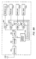
- FIGS 3 and 4 show the principal components of a preferred controller 300 according to the invention
- Figure 8 shows the arrangement of the components in a block diagram.
- the controller can display the test results in printed form 302 in any desired format and can provide real time indication of conditions on displays (e.g. , liquid crystal) for temperature 304 and pressure 306.
- Data on the conditions inside the steam sterilizer chamber is received preferably by radio, employing antenna 308.
- the data can be transmitted after the transmitter unit is removed from the sterilizer through a wired data link employing male plug 310.
- the face of the controller is also shown to include indicators (e.g. , light emitting diodes) which provide visual warning of a wet condition 312 in the sterilizer and confirmation of effective reception 314 of transmission from the transmission unit.
- Power can be provided from standard current through line 311 or from a designated source, as desired.
- the system will be capable of operation in at least of two modes: (1) a Bowie and Dick test mode, typically run once a day ( e.g. , each morning) on an empty sterilizer, and (2) a test under load.
- the particular reference temperatures, and if employed, reference pressures and moistures which are referred to to determine the effectiveness of operation of the sterilizer will differ depending on whether or not a load is present. Accordingly, the controller must be set for the particular mode for each cycle of operation and be programmed with the reference conditions for that mode.
- the load mode reference conditions will typically be unique to an individual sterilizer.
- the microprocessor is preferably programmed to receive reference temperature, pressure and moisture data by a trained operator, periodically, via data link such as 310.
- Reference to Figure 8 shows a user program data block 311 which can be a keyboard, disk drive or other suitable data entry device.
- a mode switch 318 includes a light source which will flash until a mode (as displayed on panel 316) is selected by actuating the switch.
- the controller preferably includes means which prevent the test cycle from beginning and any report to be printed until the mode switch is activated.
- the controller components are illustrated in block form for a preferred device in Figure 8 and for a simplified version in Figure 8A.
- This latter Figure shows a radio receiver 320 which receives the data transmission from the transmitter in test unit 100 inside the steam sterilizer 200 and sends the data to UART 330.
- the UART 350, address decode unit 340 manipulates the data and distributes the designated signals to digital to analog converters (DAC), e.g. strobe driven, (362, 364, 366 and 368) as needed to display the temperature 372, pressure 374, moisture 376 and transmitter temperature 378.
- DAC digital to analog converters
- the temperature display 372 is most preferred.
- the moisture is preferably handled simply by a warning light, and excessive temperatures within the transmitter itself are noted by visual indicator similar to wet indicator 312, which can be accompanied by an audible warning.
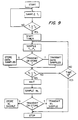
- Figure 9 is a preferred flow diagram for the operation of a test unit 100
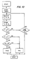
- Figure 10 is a preferred flow diagram for the operation of a controller 300.
- Figure 8 is a preferred embodiment of a controller in block diagram form showing a receiver 320, a modem 330, a UART 350, and a microprocessor 380 which drives the condition monitors 372, 374, 376 and 378.
- the microprocessor is instructed as to the mode of operation by mode switch 382, and other data can be input by user program data entry device 311 which can be a keyboard, disc drive, or the like. Output to printer 390 will generate a printed report.
- a sterilizer having a preliminary vacuum cycle is opened and the test unit 100 is placed therein.
- the sterilizer cycle is then begun, and a vacuum is drawn for the designated period of time.
- This is followed by the introduction of steam at a designated temperature (e.g., 140.6°C (285°F)) for a designated time (e.g. , 3.5 minutes).
- the test unit continuously monitors the temperature. Analog data from this and other transducers is continuously digitized and presented to the microprocessor.
- T o When the temperature reaches a designated T o value, the test unit is turned on to collect and store test temperature values, T 1 and P 1 . Temperature T 1 and the signal generated are indicative of the temperature at the location of temperature sensor 122 in cavity 115. Pressure P 1 and the signal generated, are indicative of the pressure within cavity 115. Stored within memory is reference temperature information, and a signal T r is generated indicative of this reference temperature.
- the reference tempeature can be a predetermined temperature, e.g. 140.6°C (285°F), or a calculated value based on a computed average of selected values from earlier runs, e.g. , the last ten Bowie and Dick mode temperatures.
- the controller 300 or functional equivalent preferably receives transmitted test data and processes it in accordance with Figure 10.
- the controller receives and stores data indicative of T 1 , P 1 and M 1 , and then compares signal T 1 to a stored signal T r which is typically the intended sterilization temperature. If this test is met and if pressure data is being treated, signal P 1 will be compared to signal P r indicative of a reference pressure.
- the reference pressure can be a pressure obtained from stored steam table information to indicate the pressure for saturated steam at that temperature with or without a designated tolerance.
- the signal P r can take into account a permissable -15.0° or -12.2°C (5° or 10°F) degrees of superheat. In other words P r can be slightly higher than the value for saturated steam at T 1 .
- the logic is queried to assure that the test time, or shorter time for the comparison, has not expired. Moisture data can then be taken and compared to a reference moisture, and a report printed.
Claims (21)
- Procédé pour déterminer l'efficacité de l'enlèvement de l'air d'un stérilisateur à vapeur, le procédé comprenant les étapes consistant à placer un dispositif de test (100) à l'intérieur de la chambre (202) d'un stérilisateur (200), caractérisé en ce que le dispositif (100) est capable de concentrer tout air présent dans la chambre à l'emplacement d'un capteur de température (122), mesurer la température de l'atmosphère à l'emplacement ; avec le capteur (122) générer un signal (T1) représentatif de la température détectée ; générer un signal (Tr) représentatif d'une température de référence ; comparer le signal T1 au signal Tr ; et générer un signal représentatif d'une condition de passage ou d'une condition de défaillance sur la base des résultats de la comparaison.
- Procédé selon la revendication 1, caractérisé en ce que ledit dispositif de test (100) inclut une cavité (115) de forme allongée ayant une ouverture à une première extrémité pour permettre l'entrée de vapeur et un refroidisseur thermique (112) placé dans la cavité (115) et capable de condenser la vapeur, ledit capteur de température (122) étant placé à l'intérieur de la cavité (115) à l'opposé de ladite première extrémité.
- Procédé selon la revendication 1 ou 2, caractérisé en ce que le procédé comprend les étapes consistant à : au moyen d'un capteur d'humidité (126) en contact avec le refroidisseur thermique (112) et capable de détecter l'humidité liquide, générer un signal (M1) représentatif de celle-ci ; générer un signal (Mr) représentatif d'une valeur de référence ; comparer M1 au signal Mr et générer un signal représentatif d'une condition de passage ou d'une condition de défaillance sur la base des résultats de la comparaison.
- Procédé selon l'une quelconque des revendications précédentes, caractérisé en ce que la présence d'un liquide dispersée dans la vapeur est détectée ; et la valeur détectée de l'eau liquide dispersée est comparée à un niveau cible ; et un signal représentatif d'une condition de passage ou d'une condition de défaillance est généré sur la base des résultats de la comparaison.
- Procédé selon l'une quelconque des revendications précédentes, caractérisé en ce que le signal ou chaque signal généré dans le stérilisateur est transmis par transmission radio à un récepteur (300) placé à l'extérieur de la chambre (202).
- Procédé selon l'une quelconque des revendications précédentes, caractérisé en ce que le procédé comprend l'étape consistant à afficher les résultats de la comparaison ou de chaque comparaison sous forme visuelle archivable.
- Procédé selon la revendication 6, caractérisé en ce que le procédé comprend les étapes consistant à mémoriser le signal ou chaque signal généré à l'intérieur du moyen de mémorisation (120) à l'intérieur de ladite chambre (202) ; relier ledit moyen de mémorisation (120) à un circuit logique (300) à l'extérieur de ladite chambre (202) pour effectuer ladite comparaison ; et afficher les résultats de ladite comparaison sous une forme visuelle archivable.
- Procédé selon l'une quelconque des revendications précédentes, caractérisé en ce que le procédé comprend l'étape consistant à calculer ladite température de référence comme la moyenne des températures sélectionnées mémorisées dans le nombre de cycles le plus dernier prédéterminé du mode désigné de fonctionnement.
- Procédé selon l'une quelconque des revendications précédentes, caractérisé en ce que le procédé est établi pour fonctionner en mode de charge et la température de référence est sélectionnée pour procurer la sensibilité appropriée pour déterminer l'efficacité de l'exclusion d'air de la chambre (202) dans des conditions de charge opérationnelles.
- Procédé selon l'une quelconque des revendications 1 à 8, caractérisé en ce que le procédé est établi en mode Bowie et Dick et la température de référence est sélectionnée pour procurer une sensibilité appropriée pour déterminer l'efficacité de l'exclusion d'air de la chambre (202) dans des conditions sans charge.
- Procédé selon l'une quelconque des revendications précédentes, caractérisé en ce que le procédé comprend les étapes consistant à détecter la pression à l'intérieur de ladite chambre (202) et générer un signal (P1) représentatif de celle-ci ; identifier à partir des données de la table de vapeur la pression pour la vapeur saturée à la température correspondant au signal T1 et générer un signal (Pr) représentatif de celle-ci ; comparer le signal P1 ; et générer un signal représentatif d'une condition de passage ou d'une condition de défaillance sur la base des résultats de la comparaison.
- Système pour déterminer l'efficacité de l'enlèvement d'air d'un stérilisateur (202), le système comprenant un dispositif de test (100 (qui peut être placé à l'intérieur d'une chambre de stérilisation (202) et capable de détecter la température à cet emplacement et générer un signal (T1) représentatif de celle-ci, et incluant un capteur de température (122) ; un moyen pour générer un signal (Tr) représentatif d'une température de référence, un moyen pour comparer le signal T1 au signal Tr ; et un moyen pour générer un signal représentatif d'une condition de passage ou d'une condition de défaillance sur la base des résultats de la comparaison, caractérisé en ce que le dispositif de test (100) comprend une cavité (115) de forme allongée ayant une ouverture à une première extrémité pour permettre l'entrée de la vapeur, et un refroidisseur thermique (112) placé dans la cavité (115) et capable de condenser la vapeur, et en ce que le capteur de température (122) est placé à l'intérieur de la cavité (115) sur un côté opposé au refroidisseur thermique (112) à ladite première extrémité.
- Système selon la revendication 12, caractérisé en ce qu'il est prévu un moyen (124) pour détecter la pression à l'intérieur de ladite chambre (202) et pour générer un signal (P1) représentatif de celle-ci ; et un moyen (126) pour détecter l'humidité à l'intérieur de ladite chambre (202) et pour générer un signal (M1) représentatif de celle-ci.
- Système selon la revendication 12 ou 13, caractérisé en ce qu'il est prévu un moyen de transmission radio (120) pour transmettre le signal ou chaque signal généré à un emplacement à l'extérieur de la chambre de stérilisation (202) par transmission radio.
- Système selon la revendication 14, caractérisé en ce qu'il est prévu un moyen (144) sensible au signal T1 pour initier ladite transmission:
- Système selon l'une quelconque des revendications 12 à 15, caractérisé en ce qu'il est prévu un contrôleur (300) comprenant un moyen pour recevoir les signaux produits à l'intérieur de la chambre (202) d'un stérilisateur à vapeur (200) ; un moyen pour générer des signaux de référence ; un moyen pour comparer les signaux reçu et de référence Tr; et un moyen pour générer un signal représentatif d'une condition de passage ou d'une condition de défaillance sur la base des résultats de la comparaison.
- Système selon la revendication 16, lorsque dépendante de la revendication 14 ou 15, caractérisé en ce que ledit moyen pour recevoir les signaux dans le contrôleur (300) comprend un récepteur radio (308).
- Système selon la revendication 16, lorsque dépendante de la revendication 12 ou 13, caractérisé en ce que ledit moyen (308) pour recevoir les signaux comprend un moyen de connecteur (310) pour coupler électriquement le contrôleur (300) au dispositif de test (100).
- Système selon l'une quelconque des revendications 12 à 18, caractérisé en ce qu'il est prévu un moyen de mémorisation (140) pour mémoriser le signal ou chaque signal produit à l'intérieur de la chambre (202) d'un stérilisateur à vapeur (200).
- système selon l'une quelconque des revendications 12 à 19, caractérisé en ce que ledit refroidisseur thermique (112) comprend un matériau poreux efficace pour condenser la vapeur dans les conditions prévalant à l'intérieur d'un stérilisateur à vapeur fonctionnant de manière satisfaisante.
- Système selon l'une quelconque des revendications 12 à 20, caractérisé en ce qu'il est prévu un moyen de commutation de mode (318) pouvant être actionné par un opérateur, et un moyen associé audit moyen de commutation de mode (318) pour empêcher l'achèvement d'une séquence de test jusqu'à ce que ledit commutateur soit actionné par l'opérateur.
Applications Claiming Priority (3)
| Application Number | Priority Date | Filing Date | Title |
|---|---|---|---|
| US87856492A | 1992-05-05 | 1992-05-05 | |
| US878564 | 1992-05-05 | ||
| PCT/US1993/004233 WO1993021964A1 (fr) | 1992-05-05 | 1993-05-05 | Appareil et procede de test pour sterilisateur |
Publications (3)
| Publication Number | Publication Date |
|---|---|
| EP0671956A1 EP0671956A1 (fr) | 1995-09-20 |
| EP0671956A4 EP0671956A4 (fr) | 1995-10-25 |
| EP0671956B1 true EP0671956B1 (fr) | 2002-08-21 |
Family
ID=25372289
Family Applications (1)
| Application Number | Title | Priority Date | Filing Date |
|---|---|---|---|
| EP93911067A Expired - Lifetime EP0671956B1 (fr) | 1992-05-05 | 1993-05-05 | Appareil et procede de test pour sterilisateur |
Country Status (7)
| Country | Link |
|---|---|
| US (2) | US5422276A (fr) |
| EP (1) | EP0671956B1 (fr) |
| AT (1) | ATE222506T1 (fr) |
| CA (1) | CA2135198C (fr) |
| DE (1) | DE69332226T2 (fr) |
| ES (1) | ES2183813T3 (fr) |
| WO (1) | WO1993021964A1 (fr) |
Cited By (1)
| Publication number | Priority date | Publication date | Assignee | Title |
|---|---|---|---|---|
| EP1662234A1 (fr) | 2004-11-24 | 2006-05-31 | ebro Electronic GmbH & Co. KG | Dispositif destiné à l'enregistrement au stockage de données de mensure |
Families Citing this family (65)
| Publication number | Priority date | Publication date | Assignee | Title |
|---|---|---|---|---|
| JPH01207070A (ja) * | 1987-10-22 | 1989-08-21 | Jr Robert E Duthie | 滅菌方法および装置 |
| AU739691B2 (en) * | 1994-05-27 | 2001-10-18 | Minnesota Mining And Manufacturing Company | Electronic test pack using parametric measurements for sterilizers |
| ES2212963T3 (es) * | 1994-05-27 | 2004-08-16 | Minnesota Mining And Manufacturing Company | Equipo electronico de prueba que utiliza mediciones de parametros para esterilizadores. |
| ES2175140T3 (es) * | 1995-10-06 | 2002-11-16 | Minnesota Mining & Mfg | Sistema de prueba para esterilizadores. |
| US6323032B1 (en) | 1996-10-07 | 2001-11-27 | 3M Innovative Properties Company | Sterilizer testing systems |
| FR2740974B1 (fr) * | 1995-11-09 | 1999-06-04 | Mercey Gilles | Procede et dispositif de verification de bon fonctionnement d'un sterilisateur |
| EP0776669A1 (fr) | 1995-11-27 | 1997-06-04 | Minnesota Mining And Manufacturing Company | Dispositif de test pour stérilisateurs |
| US6156267A (en) * | 1996-02-16 | 2000-12-05 | Steris Corporation | Apparatus and method for real-time monitoring and control of anti-microbial processing |
| US5788925A (en) * | 1996-02-16 | 1998-08-04 | Steris Corporation | Method for real time monitoring and control of load sterilization and parametric release |
| EP0808631A1 (fr) * | 1996-05-24 | 1997-11-26 | Intermedical S.A.H. | Dispositif de mesure destiné à surveiller les conditions de stérilisation |
| USD404828S (en) * | 1996-10-07 | 1999-01-26 | Miura Co., Ltd. | Sterilizer |
| USD405191S (en) * | 1996-12-24 | 1999-02-02 | Miura Co., Ltd. | Sterilizer |
| GB9701756D0 (en) * | 1997-01-29 | 1997-03-19 | Minnesota Mining & Mfg | Data transfer apparatus for an electronic device |
| GB9701786D0 (en) * | 1997-01-29 | 1997-03-19 | Minnesota Mining & Mfg | Electronic device having a protective framework |
| US7556767B2 (en) * | 1997-12-17 | 2009-07-07 | Ethicon, Inc. | Integrated washing and sterilization process |
| US20050163655A1 (en) * | 1997-06-11 | 2005-07-28 | Szu-Min Lin | Integrated washing and sterilization process |
| US6394111B1 (en) | 1997-06-11 | 2002-05-28 | Ethicon, Inc. | Detection of cleanliness of a medical device during a washing process |
| US7246627B2 (en) * | 1997-06-11 | 2007-07-24 | Ethicon, Inc. | Monitoring of cleaning process |
| US5992436A (en) * | 1997-07-11 | 1999-11-30 | Armstrong International, Inc. | Monitoring steam traps using RF signaling |
| GB9727533D0 (en) * | 1997-12-22 | 1998-02-25 | Minnesota Mining & Mfg | Housing for a sterilization monitoring device |
| GB9820029D0 (en) * | 1997-12-22 | 1998-11-04 | Minnesota Mining & Mfg | Sterilant challenge device for a sterilization monitoring system |
| US6630352B1 (en) | 1997-12-22 | 2003-10-07 | 3M Innovative Properties Company | Sterilant challenge device for a sterilization monitoring system |
| DE19852793A1 (de) * | 1998-11-16 | 2000-05-18 | Muenchner Medizin Mechanik | Sterilisator mit einem Meßwertaufnehmer und Verfahren zur Überwachung des Meßwertaufnehmers |
| US20100024244A1 (en) * | 1999-05-20 | 2010-02-04 | Potter Gary J | Heater and controls for extraction of moisture and biological organisms from structures |
| US20110064607A1 (en) * | 1999-05-28 | 2011-03-17 | Thermapure, Inc. | Method for removing or treating harmful biological organisms and chemical substances |
| US8272143B1 (en) | 2002-02-20 | 2012-09-25 | David Hedman | System and process for removing or treating harmful biological and organic substances within structures and enclosures |
| US8256135B2 (en) * | 1999-05-28 | 2012-09-04 | Thermapure, Inc. | Method for removing or treating harmful biological and chemical substances within structures and enclosures |
| US8221678B2 (en) * | 2002-02-20 | 2012-07-17 | Hedman David E | System and process for removing or treating harmful biological and organic substances within an enclosure |
| US7837932B2 (en) * | 1999-05-28 | 2010-11-23 | Thermapure, Inc. | Method for removing or treating harmful biological organisms and chemical substances |
| US6318151B1 (en) * | 1999-07-26 | 2001-11-20 | Abbott Laboratories | Self-contained sterilant monitoring assembly and method of using same |
| WO2001007702A1 (fr) * | 1999-07-27 | 2001-02-01 | Unilever N.V. | Procede et dispositif servant a controler un processus de lavage |
| US6485979B1 (en) | 1999-08-05 | 2002-11-26 | 3M Innovative Properties Company | Electronic system for tracking and monitoring articles to be sterilized and associated method |
| US20020099572A1 (en) * | 2000-09-26 | 2002-07-25 | Dyckman John D. | Communication system for delivering sterilization test results to customers |
| DE20019360U1 (de) * | 2000-11-15 | 2001-06-21 | Bosch Albert | Messvorrichtung zur Erfassung von temperaturabhängigen Messwerten |
| JP4149807B2 (ja) * | 2000-12-15 | 2008-09-17 | ジョンソンディバーシー・インコーポレーテッド | 洗浄プロセスを監視する装置 |
| AU2002368210A1 (en) * | 2001-12-07 | 2004-05-04 | David E. Hedman | Portable decontamination unit useful in destroying harmful biological agents in contaminated objects |
| DE20201752U1 (de) * | 2002-02-05 | 2002-04-18 | Hs System Und Prozesstechnik G | Messeinrichtung zum Überwachen von Sterilisationsbedingungen |
| GB2386188B (en) * | 2002-03-08 | 2005-04-20 | Rynhart Res Ltd | A moisture meter |
| US20040058453A1 (en) * | 2002-09-20 | 2004-03-25 | 3M Innovative Properties Company | Reaction pouch comprising an analytical sensor |
| US8283176B2 (en) * | 2004-06-29 | 2012-10-09 | Dako Denmark A/S | Method of pre-treatment and staining of a biological sample and device for support of a biological sample and methods of using such device |
| CN100409903C (zh) * | 2006-02-15 | 2008-08-13 | 周宝国 | 真空灭菌器监测方法 |
| US20070240578A1 (en) * | 2006-04-12 | 2007-10-18 | Dileo Anthony | Filter with memory, communication and temperature sensor |
| DE202006006926U1 (de) * | 2006-04-29 | 2006-06-29 | Ebro Electronic Gmbh & Co. Kg | Messvorrichtung zum Überprüfen der Effektivität eines Dampfsterilisationsprozesses |
| WO2008108864A2 (fr) * | 2006-07-05 | 2008-09-12 | Hedman David E | Procédé de décontamination d'objets contaminés avec des agents biologiques nocifs |
| US20110064605A1 (en) * | 2006-07-05 | 2011-03-17 | Thermapure, Inc. | Method for treating an object contaminated with harmful biological organisms or chemical substances utilizing electromagnetic waves |
| US8050875B2 (en) | 2006-12-26 | 2011-11-01 | Rosemount Inc. | Steam trap monitoring |
| DE102008010948B4 (de) * | 2008-02-25 | 2013-10-17 | Fresenius Medical Care Deutschland Gmbh | Verfahren zum Kalibrieren eines Sensors innerhalb einer Kammer; Sensor, Disposable und Behandlungsvorrichtung mit einem solchen Sensor |
| US8808646B2 (en) | 2008-03-04 | 2014-08-19 | The Boeing Company | Wireless transmission of process data from within pressure vessels |
| US8816865B1 (en) | 2009-07-06 | 2014-08-26 | Walter T. Deacon | Method and system for measuring temperature and pressure in different regions to determine steam quality |
| US8325049B2 (en) * | 2009-07-06 | 2012-12-04 | Thermo Diagnostics Company LLC | Method and system for measuring temperature and pressure in different regions to determine steam quality |
| FR2950810B1 (fr) * | 2009-10-02 | 2012-12-07 | Sterlab | Dispositif de test pour controle d'appareil de sterilisation a previde par la vapeur d'eau |
| US8864275B2 (en) | 2011-12-14 | 2014-10-21 | Xerox Corporation | System for detecting leakage of phase change inks |
| GB201216588D0 (en) | 2012-09-18 | 2012-10-31 | 3M Innovative Properties Co | Sterilant challenge device |
| GB201216587D0 (en) * | 2012-09-18 | 2012-10-31 | 3M Innovative Properties Co | Measurement of the NCG concentration in a steam sterilizer |
| US8726539B2 (en) | 2012-09-18 | 2014-05-20 | Cambridge Engineering, Inc. | Heater and controls for extraction of moisture and biological organisms from structures |
| US10641412B2 (en) | 2012-09-28 | 2020-05-05 | Rosemount Inc. | Steam trap monitor with diagnostics |
| EP2920578A4 (fr) * | 2012-11-14 | 2016-08-10 | 3M Innovative Properties Co | Procédés et articles d'indication d'humidité après stérilisation à la vapeur |
| US11065354B2 (en) | 2013-03-15 | 2021-07-20 | 3M Innovative Properties Company | Post-steam sterilization moisture-indicating articles |
| DE102013205296A1 (de) * | 2013-03-26 | 2014-10-02 | Olympus Winter & Ibe Gmbh | Verfahren und System zur Überwachung einer Aufbereitungsvorrichtung für Endoskope |
| NL2014850B1 (nl) * | 2015-05-22 | 2017-01-31 | Dental Validation Systems B V | Testinrichting voor een autoclaaf. |
| WO2017095611A1 (fr) * | 2015-12-01 | 2017-06-08 | Maxim Integrated Products, Inc. | Systèmes et procédés d'enregistrement de données au sein d'environnements hostiles |
| US10996112B2 (en) * | 2015-12-01 | 2021-05-04 | Maxim Integrated Products, Inc. | Systems and methods for correcting lag between sensor temperature and ambient gas temperature |
| US10632220B2 (en) | 2016-09-15 | 2020-04-28 | Asp Global Manufacturing Gmbh | Biological indicator with variable resistance |
| US10863252B2 (en) * | 2018-07-07 | 2020-12-08 | Winston Johnson | Steam quality process monitor |
| CN115323030A (zh) * | 2020-10-29 | 2022-11-11 | 中科朗劢技术有限公司 | 一种用于检测空气消毒设备一次性灭菌率的装置 |
Family Cites Families (10)
| Publication number | Priority date | Publication date | Assignee | Title |
|---|---|---|---|---|
| US3967494A (en) * | 1975-02-28 | 1976-07-06 | Sybron Corporation | Method and apparatus for detecting entrapped air in a steam sterilizer |
| US3982893A (en) * | 1975-09-08 | 1976-09-28 | Sybron Corporation | Sterilizer control method and apparatus |
| US4115068A (en) * | 1977-04-06 | 1978-09-19 | Sybron Corporation | Air detecting device for steam or gas sterilizers |
| US4372916A (en) * | 1979-11-06 | 1983-02-08 | American Sterilizer Company | Establishing and ascertaining desired air removal in steam sterilization |
| US4309381A (en) * | 1979-11-06 | 1982-01-05 | American Sterilizer Company | Establishing and ascertaining desired air removal in steam sterilization |
| US4486387A (en) * | 1982-06-16 | 1984-12-04 | Propper Manufacturing Co., Inc. | Disposable prevacuum steam sterilizer test device |
| US4596696A (en) * | 1983-11-15 | 1986-06-24 | Sybron Corporation | Disposable sterilizer mechanical air removal test pack |
| US4594223A (en) * | 1984-12-20 | 1986-06-10 | American Sterilizer Company | Device for detecting the presence of noncondensable gas in steam sterilizers |
| US4909070A (en) * | 1987-10-12 | 1990-03-20 | Smith Jeffery B | Moisture sensor |
| US5066464A (en) * | 1990-01-17 | 1991-11-19 | Propper Manufacturing Company, Inc. | Prevacuum steam sterilization test pack |
-
1993
- 1993-05-05 DE DE69332226T patent/DE69332226T2/de not_active Expired - Lifetime
- 1993-05-05 CA CA002135198A patent/CA2135198C/fr not_active Expired - Lifetime
- 1993-05-05 WO PCT/US1993/004233 patent/WO1993021964A1/fr active IP Right Grant
- 1993-05-05 EP EP93911067A patent/EP0671956B1/fr not_active Expired - Lifetime
- 1993-05-05 ES ES93911067T patent/ES2183813T3/es not_active Expired - Lifetime
- 1993-05-05 AT AT93911067T patent/ATE222506T1/de not_active IP Right Cessation
-
1994
- 1994-06-22 US US08/263,792 patent/US5422276A/en not_active Expired - Lifetime
- 1994-06-22 US US08/263,801 patent/US5491092A/en not_active Expired - Lifetime
Cited By (2)
| Publication number | Priority date | Publication date | Assignee | Title |
|---|---|---|---|---|
| EP1662234A1 (fr) | 2004-11-24 | 2006-05-31 | ebro Electronic GmbH & Co. KG | Dispositif destiné à l'enregistrement au stockage de données de mensure |
| DE102004056796A1 (de) * | 2004-11-24 | 2006-06-01 | Ebro Electronic Gmbh & Co. Kg | Vorrichtung zur Erfassung und Speicherung von Messwerten |
Also Published As
| Publication number | Publication date |
|---|---|
| ATE222506T1 (de) | 2002-09-15 |
| ES2183813T3 (es) | 2003-04-01 |
| US5422276A (en) | 1995-06-06 |
| US5491092A (en) | 1996-02-13 |
| CA2135198C (fr) | 2005-03-15 |
| EP0671956A1 (fr) | 1995-09-20 |
| DE69332226T2 (de) | 2003-04-17 |
| CA2135198A1 (fr) | 1993-11-11 |
| WO1993021964A1 (fr) | 1993-11-11 |
| DE69332226D1 (de) | 2002-09-26 |
| EP0671956A4 (fr) | 1995-10-25 |
Similar Documents
| Publication | Publication Date | Title |
|---|---|---|
| EP0671956B1 (fr) | Appareil et procede de test pour sterilisateur | |
| US5565634A (en) | Electronic test pack using parametric measurements for sterlizers | |
| EP0902659B1 (fr) | Procede et dispositif de detection de fuites dans des linges steriles chirurgicaux | |
| JP7391929B2 (ja) | 真空チャンバ内の水分を検出するための装置及び方法 | |
| JPH11513285A (ja) | 滅菌器検査装置 | |
| KR20050120768A (ko) | 고처리량 생물학적 지표 리더 기술 분야 | |
| EP0834324A2 (fr) | Méthode et appareil pour détecter les inclusions d'eau dans les chambres à vide | |
| EP0621810A1 (fr) | Desinfection de reservoirs. | |
| US3996802A (en) | Device for testing sterilization apparatus | |
| US20220175994A1 (en) | Load volume determination method for a sterilization apparatus | |
| US20210353792A1 (en) | Method and apparatus for decontaminating articles in a steam sterilizer at low temperature | |
| Gillespie et al. | Autoclaves and their dangers and safety in laboratories | |
| JPH0528774B2 (fr) | ||
| Zhan et al. | Study on temperature delay of non-metallic medical instruments in pressure steam sterilization | |
| Kirk et al. | Detection of Superheated Steam during Sterilization Using Biological Indicators | |
| AU739691B2 (en) | Electronic test pack using parametric measurements for sterilizers | |
| WO2020098902A1 (fr) | Indicateur effilé à utiliser dans des dispositifs d'épreuve de procédé | |
| Slowiak | Steam Sterilization Failures: Causes and Detection |
Legal Events
| Date | Code | Title | Description |
|---|---|---|---|
| PUAI | Public reference made under article 153(3) epc to a published international application that has entered the european phase |
Free format text: ORIGINAL CODE: 0009012 |
|
| 17P | Request for examination filed |
Effective date: 19950209 |
|
| AK | Designated contracting states |
Kind code of ref document: A1 Designated state(s): AT BE CH DE DK ES FR GB IE IT LI LU NL SE |
|
| A4 | Supplementary search report drawn up and despatched |
Effective date: 19950911 |
|
| AK | Designated contracting states |
Kind code of ref document: A4 Designated state(s): AT BE CH DE DK ES FR GB IE IT LI LU NL SE |
|
| RHK1 | Main classification (correction) |
Ipc: A61L 2/26 |
|
| 17Q | First examination report despatched |
Effective date: 19960711 |
|
| GRAG | Despatch of communication of intention to grant |
Free format text: ORIGINAL CODE: EPIDOS AGRA |
|
| GRAG | Despatch of communication of intention to grant |
Free format text: ORIGINAL CODE: EPIDOS AGRA |
|
| GRAH | Despatch of communication of intention to grant a patent |
Free format text: ORIGINAL CODE: EPIDOS IGRA |
|
| GRAG | Despatch of communication of intention to grant |
Free format text: ORIGINAL CODE: EPIDOS AGRA |
|
| GRAH | Despatch of communication of intention to grant a patent |
Free format text: ORIGINAL CODE: EPIDOS IGRA |
|
| GRAG | Despatch of communication of intention to grant |
Free format text: ORIGINAL CODE: EPIDOS AGRA |
|
| GRAH | Despatch of communication of intention to grant a patent |
Free format text: ORIGINAL CODE: EPIDOS IGRA |
|
| GRAG | Despatch of communication of intention to grant |
Free format text: ORIGINAL CODE: EPIDOS AGRA |
|
| GRAH | Despatch of communication of intention to grant a patent |
Free format text: ORIGINAL CODE: EPIDOS IGRA |
|
| GRAG | Despatch of communication of intention to grant |
Free format text: ORIGINAL CODE: EPIDOS AGRA |
|
| GRAH | Despatch of communication of intention to grant a patent |
Free format text: ORIGINAL CODE: EPIDOS IGRA |
|
| 18D | Application deemed to be withdrawn |
Effective date: 20000207 |
|
| GRAH | Despatch of communication of intention to grant a patent |
Free format text: ORIGINAL CODE: EPIDOS IGRA |
|
| 18RA | Request filed for re-establishment of rights before grant |
Effective date: 20010531 |
|
| D18Z | Request filed for re-establishment of rights before grant (deleted) | ||
| R18D | Application deemed to be withdrawn (corrected) |
Effective date: 20010531 |
|
| D18D | Application deemed to be withdrawn (deleted) | ||
| GRAA | (expected) grant |
Free format text: ORIGINAL CODE: 0009210 |
|
| AK | Designated contracting states |
Kind code of ref document: B1 Designated state(s): AT BE CH DE DK ES FR GB IE IT LI LU NL SE |
|
| PG25 | Lapsed in a contracting state [announced via postgrant information from national office to epo] |
Ref country code: NL Free format text: LAPSE BECAUSE OF FAILURE TO SUBMIT A TRANSLATION OF THE DESCRIPTION OR TO PAY THE FEE WITHIN THE PRESCRIBED TIME-LIMIT Effective date: 20020821 Ref country code: LI Free format text: LAPSE BECAUSE OF FAILURE TO SUBMIT A TRANSLATION OF THE DESCRIPTION OR TO PAY THE FEE WITHIN THE PRESCRIBED TIME-LIMIT Effective date: 20020821 Ref country code: CH Free format text: LAPSE BECAUSE OF FAILURE TO SUBMIT A TRANSLATION OF THE DESCRIPTION OR TO PAY THE FEE WITHIN THE PRESCRIBED TIME-LIMIT Effective date: 20020821 Ref country code: BE Free format text: LAPSE BECAUSE OF FAILURE TO SUBMIT A TRANSLATION OF THE DESCRIPTION OR TO PAY THE FEE WITHIN THE PRESCRIBED TIME-LIMIT Effective date: 20020821 Ref country code: AT Free format text: LAPSE BECAUSE OF FAILURE TO SUBMIT A TRANSLATION OF THE DESCRIPTION OR TO PAY THE FEE WITHIN THE PRESCRIBED TIME-LIMIT Effective date: 20020821 |
|
| REF | Corresponds to: |
Ref document number: 222506 Country of ref document: AT Date of ref document: 20020915 Kind code of ref document: T |
|
| REG | Reference to a national code |
Ref country code: CH Ref legal event code: EP |
|
| REF | Corresponds to: |
Ref document number: 69332226 Country of ref document: DE Date of ref document: 20020926 |
|
| REG | Reference to a national code |
Ref country code: IE Ref legal event code: FG4D |
|
| PG25 | Lapsed in a contracting state [announced via postgrant information from national office to epo] |
Ref country code: DK Free format text: LAPSE BECAUSE OF FAILURE TO SUBMIT A TRANSLATION OF THE DESCRIPTION OR TO PAY THE FEE WITHIN THE PRESCRIBED TIME-LIMIT Effective date: 20021121 |
|
| NLV1 | Nl: lapsed or annulled due to failure to fulfill the requirements of art. 29p and 29m of the patents act | ||
| REG | Reference to a national code |
Ref country code: CH Ref legal event code: PL |
|
| ET | Fr: translation filed | ||
| REG | Reference to a national code |
Ref country code: ES Ref legal event code: FG2A Ref document number: 2183813 Country of ref document: ES Kind code of ref document: T3 |
|
| RAP2 | Party data changed (patent owner data changed or rights of a patent transferred) |
Owner name: COLVIN, JANE E. |
|
| PG25 | Lapsed in a contracting state [announced via postgrant information from national office to epo] |
Ref country code: LU Free format text: LAPSE BECAUSE OF NON-PAYMENT OF DUE FEES Effective date: 20030505 Ref country code: IE Free format text: LAPSE BECAUSE OF NON-PAYMENT OF DUE FEES Effective date: 20030505 |
|
| PLBE | No opposition filed within time limit |
Free format text: ORIGINAL CODE: 0009261 |
|
| STAA | Information on the status of an ep patent application or granted ep patent |
Free format text: STATUS: NO OPPOSITION FILED WITHIN TIME LIMIT |
|
| 26N | No opposition filed |
Effective date: 20030522 |
|
| REG | Reference to a national code |
Ref country code: IE Ref legal event code: MM4A |
|
| PG25 | Lapsed in a contracting state [announced via postgrant information from national office to epo] |
Ref country code: IT Free format text: LAPSE BECAUSE OF NON-PAYMENT OF DUE FEES Effective date: 20050505 |
|
| PGRI | Patent reinstated in contracting state [announced from national office to epo] |
Ref country code: IT Effective date: 20080301 |
|
| PGFP | Annual fee paid to national office [announced via postgrant information from national office to epo] |
Ref country code: GB Payment date: 20120606 Year of fee payment: 20 Ref country code: FR Payment date: 20120614 Year of fee payment: 20 Ref country code: SE Payment date: 20120523 Year of fee payment: 20 |
|
| PGFP | Annual fee paid to national office [announced via postgrant information from national office to epo] |
Ref country code: IT Payment date: 20120522 Year of fee payment: 20 |
|
| PGFP | Annual fee paid to national office [announced via postgrant information from national office to epo] |
Ref country code: DE Payment date: 20120629 Year of fee payment: 20 Ref country code: ES Payment date: 20120523 Year of fee payment: 20 |
|
| REG | Reference to a national code |
Ref country code: DE Ref legal event code: R071 Ref document number: 69332226 Country of ref document: DE |
|
| REG | Reference to a national code |
Ref country code: DE Ref legal event code: R071 Ref document number: 69332226 Country of ref document: DE |
|
| REG | Reference to a national code |
Ref country code: GB Ref legal event code: PE20 Expiry date: 20130504 |
|
| PG25 | Lapsed in a contracting state [announced via postgrant information from national office to epo] |
Ref country code: DE Free format text: LAPSE BECAUSE OF EXPIRATION OF PROTECTION Effective date: 20130507 Ref country code: GB Free format text: LAPSE BECAUSE OF EXPIRATION OF PROTECTION Effective date: 20130504 |
|
| REG | Reference to a national code |
Ref country code: ES Ref legal event code: FD2A Effective date: 20130806 |
|
| PG25 | Lapsed in a contracting state [announced via postgrant information from national office to epo] |
Ref country code: ES Free format text: LAPSE BECAUSE OF EXPIRATION OF PROTECTION Effective date: 20130506 |