EP0671956B1 - Sterilizer test method and apparatus - Google Patents
Sterilizer test method and apparatus Download PDFInfo
- Publication number
- EP0671956B1 EP0671956B1 EP93911067A EP93911067A EP0671956B1 EP 0671956 B1 EP0671956 B1 EP 0671956B1 EP 93911067 A EP93911067 A EP 93911067A EP 93911067 A EP93911067 A EP 93911067A EP 0671956 B1 EP0671956 B1 EP 0671956B1
- Authority
- EP
- European Patent Office
- Prior art keywords
- signal
- steam
- chamber
- indicative
- generating
- Prior art date
- Legal status (The legal status is an assumption and is not a legal conclusion. Google has not performed a legal analysis and makes no representation as to the accuracy of the status listed.)
- Expired - Lifetime
Links
Images


Classifications
-
- A—HUMAN NECESSITIES
- A61—MEDICAL OR VETERINARY SCIENCE; HYGIENE
- A61L—METHODS OR APPARATUS FOR STERILISING MATERIALS OR OBJECTS IN GENERAL; DISINFECTION, STERILISATION OR DEODORISATION OF AIR; CHEMICAL ASPECTS OF BANDAGES, DRESSINGS, ABSORBENT PADS OR SURGICAL ARTICLES; MATERIALS FOR BANDAGES, DRESSINGS, ABSORBENT PADS OR SURGICAL ARTICLES
- A61L2/00—Methods or apparatus for disinfecting or sterilising materials or objects other than foodstuffs or contact lenses; Accessories therefor
- A61L2/26—Accessories or devices or components used for biocidal treatment
- A61L2/28—Devices for testing the effectiveness or completeness of sterilisation, e.g. indicators which change colour
Definitions
- the invention relates to sterilizers and, in particular, to a method and apparatus for improving the assurance of effective operation of sterilizers, especially those of the prevacuum type.
- a uniform color change (supported by a record showing a satisfactory time-temperature relationship in the chamber drain) indicated a satisfactory result and could be interpreted as showing rapid steam penetration, adequate air removal, and freedom from significant air leaks.
- Bowie and Dick type tests are typically run once a day and, if run and interpreted correctly, can determine only the condition of air leakage and can determine it only at that time.
- the sterilizer operations which are actually responsible for assuring the safety of patients are conducted under load conditions and cannot be monitored with accuracy with current technology.
- Joslyn disclosed a method and apparatus for detecting entrapped air in a steam sterilizer.
- the device is shown outside the steam chamber to enable quantitative measurement of the amount of air or other noncondensible gas at the chamber drain.
- the device is intended for use with a sterilizer of the type that employs steam to displace air. The device does not, however, eliminate the need for a Bowie and Dick test.
- Chamberlain and Cook monitor the temperature of the exhausted steam at the drain and the pressure within the chamber, and compare these to the steam table values to determine if all the air has been evacuated.
- the positioning of sensors within the chamber, especially by retrofitting, can, however, create further problem areas for future concern.
- Joslyn describes a small device for indicating air inside a sterilization chamber of the type used with steam or ethylene oxide.
- the device includes an upright tube holding an indicator strip and a heat sink. Air is said to pass into the tube where it interferes with the steam contacting the indicator strip.
- the present invention provides methods and apparatus for determining the effectiveness of air removal from a steam sterilizer and for monitoring the sterilization conditions therein.
- the apparatus provides a test device, a controller and a system which utilizes one or both.
- the methods achieve the objects of the invention in its broad as well as specific aspects.
- the test device comprises: a wall member defining an elongated test cavity having an opening at one end to permit entrance of ambient gases; a temperature sensor capable of generating a signal (T 1 ) indicative of the temperature at its location at an end of the test cavity opposite from said opening; and a heat sink located in said test cavity between said opening and said temperature sensor.
- the test device will comprise: means for sensing the temperature at a location within a sterilization chamber and generating a signal (T 1 ) indicative thereof; and radio transmission means for transmitting signal T 1 to a location outside of the sterilization chamber.
- storage means are provided for storing signal T 1 within said chamber.
- the controller in one of its preferred forms comprises: means for receiving a signal (T 1 ) indicative of the temperature at a predetermined location within the chamber of a steam sterilizer; means for generating a signal (T r ) indicative of a reference temperature, which can be either a preselected reference temperature such as the desired sterilization temperature or a calculated temperature such as the average of selected temperatures reported in the latest of a predetermined number of cycles of operation in either two modes (namely, (1) Bowie and Dick test or (2) operation under load); means for comparing signal T 1 to signal T r ; and means for generating a signal indicative of either a pass or fail condition based on the results of the comparison.
- the means for receiving the signal T 1 can comprise a radio receiver or connector means to electrically couple the controller to the test device.
- the system in one of its embodiments comprises: a test device capable of sensing the temperature at its location and generating a signal (T 1 ) indicative thereof; means for generating a signal (T r ) indicative of a reference temperature, as above; means for comparing signal T 1 to signal T r ; and means for generating a signal indicative of either a pass or fail condition based on the results of the comparison.
- the method of the invention in one of its forms comprises: placing a test device capable of sensing a temperature within the chamber of a sterilizer and generating a signal (T 1 ) indicative of the sensed temperature; generating a signal T 1 ; generating a signal T r indicative of a reference temperature; comparing signal T 1 to signal T r ; and generating a signal indicative of either a pass or fail condition based on the results of the comparison.
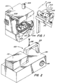
- Figure 1 illustrates a preferred system of the invention which includes a test unit 100 inside the chamber 202 of a sterilizer 200.
- the test unit is shown positioned near drain 204, for obtaining data and transmitting via radio frequency to controller 300 which is shown outside of the chamber 202.
- the system can operate by obtaining temperature data alone or in combination with pressure and/or dispersed liquid moisture data.
- the data can be transmitted from the chamber by radio to provide real time monitoring, or it can be stored within the test unit 100 for later later transmission to controller 300 such as through electrical connection, infra red data transmission, or other suitable means.
- a permanent archiveable record 302 can be generated by display means such as a thermal printer or a chart recorder. This enables accurate records to be kept, whether the system is operated in a mode to perform a Bowie and Dick type test (Bowie and Dick mode) or in a mode to monitor the operation of the sterilizer under load conditions (load mode).
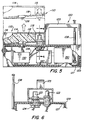
- FIG. 2 shows a preferred form of test device of the invention in greater detail, as do the partially cut away view of Figure 5 and the sectional view of Figure 6.
- the test unit 100 is seen to be comprised of two principal components, illustrated as a replaceable test module 110 and a data collection and transmission unit 120.
- data is transmitted via radio circuitry from transmission unit 120 via antenna 108 as will be described in greater detail below.
- means are also provided to store the data within the unit 100 for later processing. It is also possible to provide a test unit such as 100 which is not equipped with radio transmission means.
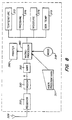
- FIG 7 corresponds to Figure 5 by showing the major components in block diagram form. Included are an array of sensors 121, namely temperature sensor 122, pressure sensor 124, moisture sensor 126, and box temperature sensor 128. Temperature sensor 122 is preferably a solid state temperature transducer, such as an Analog Devices (Maynard, MA) model AD 590 with a resolution of -17.5°C (0.5°F) and a measurement range of 125-141.1°C (257°-286°F).
- the pressure sensor 124 is preferably a pressure transducer as shown in Figures 5 and 6.
- the temperature sensor 122 and port 123 to the pressure sensor 124 are shown as component parts of replaceable test module 110.
- the moisture sensor 126 is desirably embedded within heat sink material 112 in the test module 110.
- the temperature sensor 128 will be embedded within or closely associated with the temperature-sensitive electronic components, such as multiplexer 130 within the transmission unit 120.
- the temperature sensor 128, can be similar to sensor 122 and is capable of generating a signal indicative of the temperature within the transmission unit 120 to warn of overheating.
- the temperature sensor 122 senses the temperature within test cavity 115 located at a position in the sterilizer, usually near the drain 204, where it would be most sensitive to the presence of air. All of the test devices of the present invention have the capability of obtaining temperature data by sensing the temperature within a chamber 202 and generating a signal indicative of that temperature.
- the pressure sensor 124 is optional, but preferred, and provides the ability to sense the pressure at the location of the sensed temperature and to generate a signal which corresponds to it.
- the pressure sensor 124 is preferably located within the transmission unit 120, but is open to the test module 110 through port 123 which can simply be a tube which fits into the transducer.
- the moisture sensor 126 is also preferred, but optional, and adds the ability to sense the presence of liquid water dispersed in the steam.
- Most modern sterilizers include moisture traps near the steam inlet, e.g ., at 206, to maintain wet steam at low levels, but it is an added advantage of the invention that assurance can be provided to reduce the chances that wet loads could result due to steam moisture contents greater than a target level, usually a maximum of 3%.
- moisture sensors such as those described by Smith in U.S. Patent No. 4,909,070.
- the replaceable test module 110 is designed to concentrate air to the specific location of the temperature sensor 122. It is shown to simply comprise a wall member 114 which defines an elongated test cavity 115 having an opening 116 to one end to permit entrance of ambient gases, a temperature sensor 122 as described, and a heat sink 112 in the cavity between the temperature sensor 122 and the opening 116.
- the heat sink can be of any suitable material which is capable of condensing steam and retaining the condensed steam therein.
- the heat sink material should be of a density, porosity and thermal conductivity to condense a sufficient amount of steam to cause air, if present, to collect at the end of the test chamber where the temperature sensor 122 is located. It is preferably absorbent enough to hold condensed water and, yet, dry rapidly. Gauzes or felts of cotton with or without metalic fibers should be effective as will standard central supply wrap or open-celled polymer foam.
- test unit Under conditions of use the test unit is placed within sterilizer 200 and is subjected to a vacuum before steam is applied. Steam, when introduced, will enter opening 116 and will progress into cavity 115 wherein it will begin to condense in heat sink 112. If any air is present in the steam due to a defective chamber seal, such as rubber seal 208 (or defective vacuum pump or piping), the air will remain uncondensed as the steam around it condenses. As this process continues, air, to the extent present, will concentrate at the rear of test cavity 115 and insulate the temperature sensor 122 from the heat of the steam.
- a defective chamber seal such as rubber seal 208 (or defective vacuum pump or piping
- the replaceable test module 110 is desirably in cartridge form which can simply be snapped into and out of position (see Figure 5). It is recommended that these modules be replaced periodically, e.g. weekly or monthly, and whenever subjected to excessively wet steam. Good hospital practice would dictate eliminating the variability which could arise by using a wet test module or one which has been used for a period of time which would permit corrosion of the sensors or degradation of the heat sink material 112 by steam.
- the cartridges When employed in the load mode to monitor the conditions during sterilization, the cartridges may be changed after each cycle to assure that a dry cartridge at room temperature is present at the start of each run. These cartriges may be reused several times. In one embodiment, it is desireable to provide means for preventingoperation of the unit in the load mode unless the cartridge has been replaced.
- bottom wall 119 which slopes away from the sensors to prevent liquid water from collecting at that location. When placed on a level surface, liquid water flows toward opening 116.
- the transmission unit 120 is shown to have a casing 129 with an internal layer of insulation 127 (shown here as foamed plastic) and an external handle 125 for ease of handling. Potting in a high-- mass, low-thermal-conductivity material is also effective.
- the casing and insulation together should provide temperature protection for the sensitive internal components up to at least about 143.3°C (290°F), a vacuum of less than 12.7mm ( 1 / 2 inch) of mercury and a pressure differential of at least 5 atmospheres.
- the transmitting antenna 108 is a length of 1/4-- wave wire located perpendicular to the base of casing 129 which acts as a ground plane.
- Unit 150 Transmission of the data is effected by unit 150 shown in Figure 5 which includes UART 152 (universal asynchronous receiver-transmitter), modem 156 and radio transmitter 158.
- UART 152 universal asynchronous receiver-transmitter
- modem 156 can be an Intersil 6402 unit and the modem and transmitter can be combined as in an FM unit such as a Motorola RNet 9600 series.
- Power is preferably provided by a battery pack, preferably rechargeable.
- Figure 7 shows, in addition to the multiplexer 130 which receives the signals from the sensors and distributes them as called for, a signal processing unit 140 and a transmitter and modem unit 150.
- a suitable transmittter is an RNet 9600 unit manufactured by Motorola Inc. Radius Division, schaumberg, IL, which transmits at 464 MHz FM with a frequency deviation of 7.5 KHz.
- the signal processing unit 140 can include an analog to digital converter (ADC) which digitizes the analog signals from the multiplexer, a timing and control unit 144 which instructs the multiplexer on the distribution of signals from the sensors to the ADC 142.
- ADC analog to digital converter
- the sensors are in one embodiment sequentially sampled at a 2 Hz rate and digitized to 6 bits, and two address bits are appended to identify from which of the four sensors the data word is generated.
- the 8-bit words are applied sequentially to UART 152 which converts them to a standard 9600 baud even parity 2-stop bit message.
- a microprocessor 146 can be employed to enable storage and manipulation of digitized signals from the sensors.
- a microprocessor or other controller can receive signals representative of the temperature within the sterilizer, compare this to a signal representative of a designated temperature (T o ) for powering up the transmitter, and subject to the results of the comparison, either waiting or powering up the transmitter to send data to the external controller 300.
- T o a designated temperature
- the same sequence can be followed to shut down the unit when the temperature drops below T o .
- the unit can be shut down and a warning given when the temperature exceeds a preselected upper value.
- the microprocessor can also be provided with means to store the sensor data for transmission to the controller or other signal processor only after removal from the chamber.
- a hard data link such as by female receptacle 128 on the test device 100 and a male plug 310 on the control unit can be provided to electrically couple the two units.
- other data transmission means including those based on infrared transmission, can be employed.
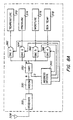
- FIGS 3 and 4 show the principal components of a preferred controller 300 according to the invention
- Figure 8 shows the arrangement of the components in a block diagram.
- the controller can display the test results in printed form 302 in any desired format and can provide real time indication of conditions on displays (e.g. , liquid crystal) for temperature 304 and pressure 306.
- Data on the conditions inside the steam sterilizer chamber is received preferably by radio, employing antenna 308.
- the data can be transmitted after the transmitter unit is removed from the sterilizer through a wired data link employing male plug 310.
- the face of the controller is also shown to include indicators (e.g. , light emitting diodes) which provide visual warning of a wet condition 312 in the sterilizer and confirmation of effective reception 314 of transmission from the transmission unit.
- Power can be provided from standard current through line 311 or from a designated source, as desired.
- the system will be capable of operation in at least of two modes: (1) a Bowie and Dick test mode, typically run once a day ( e.g. , each morning) on an empty sterilizer, and (2) a test under load.
- the particular reference temperatures, and if employed, reference pressures and moistures which are referred to to determine the effectiveness of operation of the sterilizer will differ depending on whether or not a load is present. Accordingly, the controller must be set for the particular mode for each cycle of operation and be programmed with the reference conditions for that mode.
- the load mode reference conditions will typically be unique to an individual sterilizer.
- the microprocessor is preferably programmed to receive reference temperature, pressure and moisture data by a trained operator, periodically, via data link such as 310.
- Reference to Figure 8 shows a user program data block 311 which can be a keyboard, disk drive or other suitable data entry device.
- a mode switch 318 includes a light source which will flash until a mode (as displayed on panel 316) is selected by actuating the switch.
- the controller preferably includes means which prevent the test cycle from beginning and any report to be printed until the mode switch is activated.
- the controller components are illustrated in block form for a preferred device in Figure 8 and for a simplified version in Figure 8A.
- This latter Figure shows a radio receiver 320 which receives the data transmission from the transmitter in test unit 100 inside the steam sterilizer 200 and sends the data to UART 330.
- the UART 350, address decode unit 340 manipulates the data and distributes the designated signals to digital to analog converters (DAC), e.g. strobe driven, (362, 364, 366 and 368) as needed to display the temperature 372, pressure 374, moisture 376 and transmitter temperature 378.
- DAC digital to analog converters
- the temperature display 372 is most preferred.
- the moisture is preferably handled simply by a warning light, and excessive temperatures within the transmitter itself are noted by visual indicator similar to wet indicator 312, which can be accompanied by an audible warning.
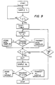
- Figure 9 is a preferred flow diagram for the operation of a test unit 100
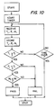
- Figure 10 is a preferred flow diagram for the operation of a controller 300.
- Figure 8 is a preferred embodiment of a controller in block diagram form showing a receiver 320, a modem 330, a UART 350, and a microprocessor 380 which drives the condition monitors 372, 374, 376 and 378.
- the microprocessor is instructed as to the mode of operation by mode switch 382, and other data can be input by user program data entry device 311 which can be a keyboard, disc drive, or the like. Output to printer 390 will generate a printed report.
- a sterilizer having a preliminary vacuum cycle is opened and the test unit 100 is placed therein.
- the sterilizer cycle is then begun, and a vacuum is drawn for the designated period of time.
- This is followed by the introduction of steam at a designated temperature (e.g., 140.6°C (285°F)) for a designated time (e.g. , 3.5 minutes).
- the test unit continuously monitors the temperature. Analog data from this and other transducers is continuously digitized and presented to the microprocessor.
- T o When the temperature reaches a designated T o value, the test unit is turned on to collect and store test temperature values, T 1 and P 1 . Temperature T 1 and the signal generated are indicative of the temperature at the location of temperature sensor 122 in cavity 115. Pressure P 1 and the signal generated, are indicative of the pressure within cavity 115. Stored within memory is reference temperature information, and a signal T r is generated indicative of this reference temperature.
- the reference tempeature can be a predetermined temperature, e.g. 140.6°C (285°F), or a calculated value based on a computed average of selected values from earlier runs, e.g. , the last ten Bowie and Dick mode temperatures.
- the controller 300 or functional equivalent preferably receives transmitted test data and processes it in accordance with Figure 10.
- the controller receives and stores data indicative of T 1 , P 1 and M 1 , and then compares signal T 1 to a stored signal T r which is typically the intended sterilization temperature. If this test is met and if pressure data is being treated, signal P 1 will be compared to signal P r indicative of a reference pressure.
- the reference pressure can be a pressure obtained from stored steam table information to indicate the pressure for saturated steam at that temperature with or without a designated tolerance.
- the signal P r can take into account a permissable -15.0° or -12.2°C (5° or 10°F) degrees of superheat. In other words P r can be slightly higher than the value for saturated steam at T 1 .
- the logic is queried to assure that the test time, or shorter time for the comparison, has not expired. Moisture data can then be taken and compared to a reference moisture, and a report printed.
Abstract
Description
- The invention relates to sterilizers and, in particular, to a method and apparatus for improving the assurance of effective operation of sterilizers, especially those of the prevacuum type.
- Reusable medical and surgical supplies must be cleaned and sterilized before storage for reuse. While absolute sterility may not be possible and testing for it is virtually impossible, strict adherence to stringent procedures can provide confidence that no viable organisms should survive. Items like dressings, gowns, drapes, and instruments must be stored ready for use, and it is essential that procedures assure that no unprocessed packages are designated sterile.
- Steam sterilization is the preferred method for use on an ongoing basis in hospitals. Conventional hospital practice entails the use of heat-activated indicator strips on each package to identify packages which have been treated in the sterilizer. The strips change color when heated sufficiently by the steam. A changed color strip does not, however, assure that the contents of the package have been heated sufficiently. This is assured only by rigorous adherence to established procedures for operating the sterilizer and for assuring its effectiveness when operated properly.
- The leakage of air, and to a lesser extent the quality of steam in terms of superheating or wetness, can prevent a steam sterilizer from achieving its objective even though the proper times and temperatures are indicated on the sterilizer instruments. Short cycle times are preferred, but can be effective only when saturated steam directly contacts the objects of sterilization to permit transfer of the latent heat of vaporization to the objects and any microbiological contamination. Superheated steam does not condense, giving up its latent heat, as readily as saturated steam. In this regard, superheated steam is similar to hot air which alone, can sterilize, but it takes much longer and has the further problem that it does not mix well with steam. As a practical matter, air is an insulator. Wet steam can also cause an insulating effect by wetting fabric and inhibiting penetration of steam.
- The presence of air in a steam sterilizer has always been a problem to be avoided. The pressure in the sterilizer and the condensation of steam in the packages tends to concentrate the air deep within the packages -- preventing direct steam contact with the objects. To better free the sterilizer of air, many modern steam sterilizers employ a preliminary evacuation step. It is essential that evacuation be effective and that air does not have a chance to inhibit sterilization. Unfortunately, leaks of air are not uncommon. One investigator (Joslyn, citing Darmody et al (1964) in Disinfection, Sterilization and Preservation; S. Block, Ed.; Third Edition, 1983, page 23,) reported that not one of ten prevacuum sterilizers tested was able to meet and maintain recommended conditions.
- In 1963, a test was suggested by researchers J. H. Bowie and J. Dick to determine if a prevacuum sterilizer was operating effectively in terms of air removal. (See J. H. Bowie, J. C. Kelsey, G. R. Thompson; The Bowie and Dick Autoclave Tape Test; The Lancet, March 16, 1963, pp 586-7) Their procedure employed preparing a test package containing at least about 25 Huckaback towels folded into eight thicknesses and stacked to a height of 10 - 11 inches, a sheet of unglazed paper bearing a cross of a specific heat-sensitive tape placed in the middle of the stack, and a suitable wrapping. A nonuniform color change on the tape after subjecting the package to a complete sterilization cycle, indicated that air was present and sterility could not be assured. A uniform color change (supported by a record showing a satisfactory time-temperature relationship in the chamber drain) indicated a satisfactory result and could be interpreted as showing rapid steam penetration, adequate air removal, and freedom from significant air leaks.
- The Bowie and Dick test was, however, subject to wide variations in the manner in which it was per- formed, and its results were very subjective. Indeed, one survey revealed that no two central service departments from a total of 35 interviewed, performed the Bowie and Dick test in the same way. (P. Ryan, The Bowie-Dick type test ... The discrepancies between theory and practice, Journal HSPD, March/April 1984, pp. 20-24.) Another survey indicated the accuracy of interpreting test scores was only 60-80% at the beginning of a study. (D. Mayworm, The Bowie-Dick type test ... Are there alternative ways?, Journal HSPD, March/April 1984, pp. 31-34.) The reliability of steam sterilizers in the medical field remains an active area of concern and research.
- Bowie and Dick type tests are typically run once a day and, if run and interpreted correctly, can determine only the condition of air leakage and can determine it only at that time. The sterilizer operations which are actually responsible for assuring the safety of patients are conducted under load conditions and cannot be monitored with accuracy with current technology. There is a present need for a more objective, less subjective, more accurate test for adequate air removal, as well as a test which can reliably, automatically monitor sterilization conditions.
- Over the years, a number of devices and techniques have been proposed to provide a greater degree of assurance that a sterilizer is operating effectively to exclude air which could prevent direct contact of steam with the objects being sterilized. In some cases, these have been adopted by hospitals convinced that they needed more reliability.
- Efforts to mechanically assure the complete removal of air from steam sterilizers have not been fully successful. Prior to the publication of the Bowie and Dick test in 1963, co-developer J. Dick had employed thermocouples in a simpler form of the test, one in a test package and another at the sterilizer drain. With most loads like the towel package, however, it is not possible to predict the location of the air bubble with the certainty required. The published version of the test replaced the thermocouple with a heat-sensitive tape to better indicate the extent of air incorporation, but still required monitoring drain temperatures.
- In U.S. Patent No. 3,967,494, Joslyn disclosed a method and apparatus for detecting entrapped air in a steam sterilizer. The device is shown outside the steam chamber to enable quantitative measurement of the amount of air or other noncondensible gas at the chamber drain. The device is intended for use with a sterilizer of the type that employs steam to displace air. The device does not, however, eliminate the need for a Bowie and Dick test.
- In U.S. Patent No. 4,372,916, Chamberlain and Cook monitor the temperature of the exhausted steam at the drain and the pressure within the chamber, and compare these to the steam table values to determine if all the air has been evacuated. The positioning of sensors within the chamber, especially by retrofitting, can, however, create further problem areas for future concern.
- In U.S. Patent No. 4,115,068, Joslyn describes a small device for indicating air inside a sterilization chamber of the type used with steam or ethylene oxide. The device includes an upright tube holding an indicator strip and a heat sink. Air is said to pass into the tube where it interferes with the steam contacting the indicator strip. Dyke and Oshlag comment on this arrangement in U.S. Patent No. 4,594,223, indicating that steam, which is less dense than air, is required to work against the weight of any accumulated air. To correct this, they describe a device having a depending glass chamber which permits air to settle to the bottom along with water from condensed steam. This device, like that of Joslyn, is simply a replacement for the Bowie and Dick test and requires interpretation of the test results -- a source of frequent errors in the original Bowie and Dick test. This is true also of a related device disclosed by Augurt in U.S. patent No. 5,066,464, which has a strip of heatsensitive material in a horizontally-disposed chamber. Similarly, U.S. Patent No. 4,486,387 to Augurt and U.S. patent No. 4,596,696 to Scoville, describe disposable test packages which have Bowie and Dick type test sheets which require interpretation.
- There remains a need for a method and apparatus to more objectively, reliably, and precisely determine the effective operation of a steam sterilizer. There is especially a need for a test which provides a positive indication of problems or the absence of them and decreases the probability that either (1) the test performance or (2) interpretation of the results will be dependent upon the skills of a particular operator -- both, areas of concern in Bowie and Dick testing.
- It is an object of the invention to provide a test method and apparatus to determine the effective air removal from a steam sterilizer with less subjectivity, and therefor, greater accuracy than the Bowie and Dick test.
- It is an object of the invention to provide an electronic test method and apparatus for determining the effectiveness of air removal from a steam sterilizer and thereby reduce common causes of error in Bowie and Dick type tests.
- It is another object of the invention to provide a method and apparatus for monitoring the sterilization conditions within a steam sterilizer as desired for a Bowie and Dick test cycle or operation under load conditions.
- It is another and more specific object of the invention to provide a method and apparatus for monitoring a steam sterilizer operation under load conditions for the presence of wet steam, superheated steam and air.
- It is an additional object of the invention to provide a reliable test method and apparatus for monitoring the operation of prevacuum sterilizers which can determine the effective evacuation of air and the quality of the steam in terms of superheating and/or wetness.
- It is yet another object of the invention to provide an apparatus and method for determining the effective air removal from the chamber of a steam sterilizer and/or steam quality therin by placing a portable test unit in the chamber and either recording the data sensed by the unit internally or transmitting it by radio to a receiver outside the chamber.
- It is a further object of the invention to provide an early warning system for a steam sterilizer which can determine the effective air removal from a prevacuum sterilizer and/or steam quality therein by comparing real time readings to either or both of standard values and average values for recent test runs for both a Bowie and Dick test cycle mode and for operation under load conditions.
- It is yet another specific object of the invention to provide a method and apparatus for determining the effective air removal from the chamber of a steam sterilizer by placing a portable test unit in the chamber and either recording the data of the unit internally or transmitting it to outside the chamber by radio.
- These and other objects are accomplished by the present invention which provides methods and apparatus for determining the effectiveness of air removal from a steam sterilizer and for monitoring the sterilization conditions therein. The apparatus provides a test device, a controller and a system which utilizes one or both. The methods achieve the objects of the invention in its broad as well as specific aspects.
- In one of its preferred forms, the test device comprises: a wall member defining an elongated test cavity having an opening at one end to permit entrance of ambient gases; a temperature sensor capable of generating a signal (T1) indicative of the temperature at its location at an end of the test cavity opposite from said opening; and a heat sink located in said test cavity between said opening and said temperature sensor. In another of its preferred forms the test device will comprise: means for sensing the temperature at a location within a sterilization chamber and generating a signal (T1) indicative thereof; and radio transmission means for transmitting signal T1 to a location outside of the sterilization chamber. In yet another, storage means are provided for storing signal T1 within said chamber.
- The controller in one of its preferred forms comprises: means for receiving a signal (T1) indicative of the temperature at a predetermined location within the chamber of a steam sterilizer; means for generating a signal (Tr) indicative of a reference temperature, which can be either a preselected reference temperature such as the desired sterilization temperature or a calculated temperature such as the average of selected temperatures reported in the latest of a predetermined number of cycles of operation in either two modes (namely, (1) Bowie and Dick test or (2) operation under load); means for comparing signal T1 to signal Tr; and means for generating a signal indicative of either a pass or fail condition based on the results of the comparison. The means for receiving the signal T1 can comprise a radio receiver or connector means to electrically couple the controller to the test device.
- The system in one of its embodiments comprises: a test device capable of sensing the temperature at its location and generating a signal (T1) indicative thereof; means for generating a signal (Tr) indicative of a reference temperature, as above; means for comparing signal T1 to signal Tr; and means for generating a signal indicative of either a pass or fail condition based on the results of the comparison.
- The method of the invention in one of its forms comprises: placing a test device capable of sensing a temperature within the chamber of a sterilizer and generating a signal (T1) indicative of the sensed temperature; generating a signal T1; generating a signal Tr indicative of a reference temperature; comparing signal T1 to signal Tr; and generating a signal indicative of either a pass or fail condition based on the results of the comparison.
- The invention will be better understood and its advantages will be more fully appreciated from the following detailed description, especially when read in light of the accompanying drawings, wherein:
- Figure 1 is a perspective view of a preferred system of the invention including a test unit inside the chamber of a steam sterilizer, positioned for recording test data and transmitting by radio to an external controller unit;
- Figure 2 is a perspective view of a preferred form of test unit of the invention;
- Figure 3 is a perspective view of a preferred form of controller unit of the invention;
- Figure 4 is a side elevation view of the controller unit shown in Figure 3, partially cut away to illustrate major components;
- Figure 5 is a side elevation view of the test unit shown in Figure 2, partially cut away to illustrate major components;
- Figure 6 is a cross-sectional view taken along line 6-6 in Figure 5;
- Figure 7 is a block diagram of the circuitry for a test unit such as shown in Figure 2;
- Figure 8 is a block diagram of the circuitry for a controller unit such as shown in Figure 3;
- Figure 8A is a block diagram illustrating a simplified circuitry for a controller unit;
- Figure 9 is a flow-chart depicting the operation of a preferred test unit according to the invention; and
- Figure 10 is a flow chart depicting the operation of a preferred controller unit according to the invention.
-
- The description which follows will focus on a preferred test unit and a preferred controller which together comprise a preferred system of the invention. This apparatus will be described in terms of the performance of the two principal method features of the invention: (1) the testing for completeness of air removal from a sterilizer chamber, and (2) the testing for effective sterilization conditions. These methods will be illustrated for the two principal modes of operation: (a) the performance of a Bowie and Dick type test, as is usually done on a once-a-day basis; and (b) monitoring the sterilizer during load conditions. The invention will be described in the specific context of prevacuum steam sterilizers, but is not strictly limited to sterilizers of this type.
- Figure 1 illustrates a preferred system of the invention which includes a
test unit 100 inside thechamber 202 of asterilizer 200. The test unit is shown positioned near drain 204, for obtaining data and transmitting via radio frequency tocontroller 300 which is shown outside of thechamber 202. The system can operate by obtaining temperature data alone or in combination with pressure and/or dispersed liquid moisture data. The data can be transmitted from the chamber by radio to provide real time monitoring, or it can be stored within thetest unit 100 for later later transmission tocontroller 300 such as through electrical connection, infra red data transmission, or other suitable means. Whatever means of transmission are selected, apermanent archiveable record 302 can be generated by display means such as a thermal printer or a chart recorder. This enables accurate records to be kept, whether the system is operated in a mode to perform a Bowie and Dick type test (Bowie and Dick mode) or in a mode to monitor the operation of the sterilizer under load conditions (load mode). - Figure 2 shows a preferred form of test device of the invention in greater detail, as do the partially cut away view of Figure 5 and the sectional view of Figure 6. The
test unit 100 is seen to be comprised of two principal components, illustrated as areplaceable test module 110 and a data collection andtransmission unit 120. In the embodiment shown, data is transmitted via radio circuitry fromtransmission unit 120 viaantenna 108 as will be described in greater detail below. Preferably, means are also provided to store the data within theunit 100 for later processing. It is also possible to provide a test unit such as 100 which is not equipped with radio transmission means. - Figure 7 corresponds to Figure 5 by showing the major components in block diagram form. Included are an array of
sensors 121, namelytemperature sensor 122,pressure sensor 124,moisture sensor 126, andbox temperature sensor 128.Temperature sensor 122 is preferably a solid state temperature transducer, such as an Analog Devices (Maynard, MA) model AD 590 with a resolution of -17.5°C (0.5°F) and a measurement range of 125-141.1°C (257°-286°F). Thepressure sensor 124 is preferably a pressure transducer as shown in Figures 5 and 6. Thetemperature sensor 122 andport 123 to thepressure sensor 124 are shown as component parts ofreplaceable test module 110. Themoisture sensor 126 is desirably embedded withinheat sink material 112 in thetest module 110. Thetemperature sensor 128 will be embedded within or closely associated with the temperature-sensitive electronic components, such asmultiplexer 130 within thetransmission unit 120. Thetemperature sensor 128, can be similar tosensor 122 and is capable of generating a signal indicative of the temperature within thetransmission unit 120 to warn of overheating. - The
temperature sensor 122, senses the temperature withintest cavity 115 located at a position in the sterilizer, usually near the drain 204, where it would be most sensitive to the presence of air. All of the test devices of the present invention have the capability of obtaining temperature data by sensing the temperature within achamber 202 and generating a signal indicative of that temperature. - The
pressure sensor 124 is optional, but preferred, and provides the ability to sense the pressure at the location of the sensed temperature and to generate a signal which corresponds to it. Thepressure sensor 124 is preferably located within thetransmission unit 120, but is open to thetest module 110 throughport 123 which can simply be a tube which fits into the transducer. - The
moisture sensor 126, is also preferred, but optional, and adds the ability to sense the presence of liquid water dispersed in the steam. Most modern sterilizers include moisture traps near the steam inlet, e.g., at 206, to maintain wet steam at low levels, but it is an added advantage of the invention that assurance can be provided to reduce the chances that wet loads could result due to steam moisture contents greater than a target level, usually a maximum of 3%. Suitable for this purpose are moisture sensors such as those described by Smith in U.S. Patent No. 4,909,070. - The
replaceable test module 110 is designed to concentrate air to the specific location of thetemperature sensor 122. It is shown to simply comprise awall member 114 which defines anelongated test cavity 115 having anopening 116 to one end to permit entrance of ambient gases, atemperature sensor 122 as described, and aheat sink 112 in the cavity between thetemperature sensor 122 and theopening 116. The heat sink can be of any suitable material which is capable of condensing steam and retaining the condensed steam therein. The heat sink material should be of a density, porosity and thermal conductivity to condense a sufficient amount of steam to cause air, if present, to collect at the end of the test chamber where thetemperature sensor 122 is located. It is preferably absorbent enough to hold condensed water and, yet, dry rapidly. Gauzes or felts of cotton with or without metalic fibers should be effective as will standard central supply wrap or open-celled polymer foam. - Under conditions of use the test unit is placed within
sterilizer 200 and is subjected to a vacuum before steam is applied. Steam, when introduced, will enter opening 116 and will progress intocavity 115 wherein it will begin to condense inheat sink 112. If any air is present in the steam due to a defective chamber seal, such as rubber seal 208 (or defective vacuum pump or piping), the air will remain uncondensed as the steam around it condenses. As this process continues, air, to the extent present, will concentrate at the rear oftest cavity 115 and insulate thetemperature sensor 122 from the heat of the steam. - If the steam is too wet, this could cause wet loads which are difficult to dry and are more easily recontaminated and may interfere with obtaining effective temperature readings. It is therefore desired to employ a
moisture sensor 126. - The
replaceable test module 110 is desirably in cartridge form which can simply be snapped into and out of position (see Figure 5). It is recommended that these modules be replaced periodically, e.g. weekly or monthly, and whenever subjected to excessively wet steam. Good hospital practice would dictate eliminating the variability which could arise by using a wet test module or one which has been used for a period of time which would permit corrosion of the sensors or degradation of theheat sink material 112 by steam. When employed in the load mode to monitor the conditions during sterilization, the cartridges may be changed after each cycle to assure that a dry cartridge at room temperature is present at the start of each run. These cartriges may be reused several times. In one embodiment, it is desireable to provide means for preventingoperation of the unit in the load mode unless the cartridge has been replaced. - Another feature of the cartridge is the provision of bottom wall 119 which slopes away from the sensors to prevent liquid water from collecting at that location. When placed on a level surface, liquid water flows toward
opening 116. - Referring again to Figure 5, the
transmission unit 120 is shown to have acasing 129 with an internal layer of insulation 127 (shown here as foamed plastic) and anexternal handle 125 for ease of handling. Potting in a high-- mass, low-thermal-conductivity material is also effective. The casing and insulation together should provide temperature protection for the sensitive internal components up to at least about 143.3°C (290°F), a vacuum of less than 12.7mm ( 1 / 2 inch) of mercury and a pressure differential of at least 5 atmospheres. The transmittingantenna 108 is a length of 1/4-- wave wire located perpendicular to the base of casing 129 which acts as a ground plane. - Transmission of the data is effected by
unit 150 shown in Figure 5 which includes UART 152 (universal asynchronous receiver-transmitter),modem 156 andradio transmitter 158. Specifically, the UART can be an Intersil 6402 unit and the modem and transmitter can be combined as in an FM unit such as a Motorola RNet 9600 series. Power is preferably provided by a battery pack, preferably rechargeable. - Figure 7 shows, in addition to the
multiplexer 130 which receives the signals from the sensors and distributes them as called for, asignal processing unit 140 and a transmitter andmodem unit 150. A suitable transmittter is an RNet 9600 unit manufactured by Motorola Inc. Radius Division, schaumberg, IL, which transmits at 464 MHz FM with a frequency deviation of 7.5 KHz. Thesignal processing unit 140 can include an analog to digital converter (ADC) which digitizes the analog signals from the multiplexer, a timing andcontrol unit 144 which instructs the multiplexer on the distribution of signals from the sensors to theADC 142. The sensors are in one embodiment sequentially sampled at a 2 Hz rate and digitized to 6 bits, and two address bits are appended to identify from which of the four sensors the data word is generated. The 8-bit words are applied sequentially toUART 152 which converts them to a standard 9600 baud even parity 2-stop bit message. - A microprocessor 146 can be employed to enable storage and manipulation of digitized signals from the sensors. For example, a microprocessor or other controller can receive signals representative of the temperature within the sterilizer, compare this to a signal representative of a designated temperature (To) for powering up the transmitter, and subject to the results of the comparison, either waiting or powering up the transmitter to send data to the
external controller 300. Similarly, the same sequence can be followed to shut down the unit when the temperature drops below To. Also the unit can be shut down and a warning given when the temperature exceeds a preselected upper value. - The microprocessor can also be provided with means to store the sensor data for transmission to the controller or other signal processor only after removal from the chamber. To facilitate this type of transfer, a hard data link such as by
female receptacle 128 on thetest device 100 and amale plug 310 on the control unit can be provided to electrically couple the two units. Alternatively, other data transmission means, including those based on infrared transmission, can be employed. - Figures 3 and 4 show the principal components of a
preferred controller 300 according to the invention, and Figure 8 shows the arrangement of the components in a block diagram. The controller can display the test results in printedform 302 in any desired format and can provide real time indication of conditions on displays (e.g., liquid crystal) fortemperature 304 andpressure 306. Data on the conditions inside the steam sterilizer chamber is received preferably by radio, employingantenna 308. Alternatively, as discussed above, the data can be transmitted after the transmitter unit is removed from the sterilizer through a wired data link employingmale plug 310. The face of the controller is also shown to include indicators (e.g., light emitting diodes) which provide visual warning of awet condition 312 in the sterilizer and confirmation ofeffective reception 314 of transmission from the transmission unit. Power can be provided from standard current throughline 311 or from a designated source, as desired. - In its preferred form, the system will be capable of operation in at least of two modes: (1) a Bowie and Dick test mode, typically run once a day (e.g., each morning) on an empty sterilizer, and (2) a test under load. The particular reference temperatures, and if employed, reference pressures and moistures which are referred to to determine the effectiveness of operation of the sterilizer, will differ depending on whether or not a load is present. Accordingly, the controller must be set for the particular mode for each cycle of operation and be programmed with the reference conditions for that mode. The load mode reference conditions will typically be unique to an individual sterilizer. The microprocessor is preferably programmed to receive reference temperature, pressure and moisture data by a trained operator, periodically, via data link such as 310. Reference to Figure 8 shows a user program data block 311 which can be a keyboard, disk drive or other suitable data entry device.
- To assure that the proper mode of operation has been selected by the operator, a
mode switch 318 includes a light source which will flash until a mode (as displayed on panel 316) is selected by actuating the switch. The controller preferably includes means which prevent the test cycle from beginning and any report to be printed until the mode switch is activated. - The controller components are illustrated in block form for a preferred device in Figure 8 and for a simplified version in Figure 8A. This latter Figure shows a
radio receiver 320 which receives the data transmission from the transmitter intest unit 100 inside thesteam sterilizer 200 and sends the data toUART 330. TheUART 350,address decode unit 340 manipulates the data and distributes the designated signals to digital to analog converters (DAC), e.g. strobe driven, (362, 364, 366 and 368) as needed to display thetemperature 372,pressure 374,moisture 376 andtransmitter temperature 378. Of these, thetemperature display 372 is most preferred. The moisture is preferably handled simply by a warning light, and excessive temperatures within the transmitter itself are noted by visual indicator similar towet indicator 312, which can be accompanied by an audible warning. - The operation of a preferred system can be followed by viewing Figures 9 and 10. Figure 9 is a preferred flow diagram for the operation of a
test unit 100, and Figure 10 is a preferred flow diagram for the operation of acontroller 300. - Figure 8 is a preferred embodiment of a controller in block diagram form showing a
receiver 320, amodem 330, aUART 350, and amicroprocessor 380 which drives the condition monitors 372, 374, 376 and 378. The microprocessor is instructed as to the mode of operation by mode switch 382, and other data can be input by user programdata entry device 311 which can be a keyboard, disc drive, or the like. Output toprinter 390 will generate a printed report. - In one preferred Bowie and Dick mode operation, a sterilizer having a preliminary vacuum cycle is opened and the
test unit 100 is placed therein. The sterilizer cycle is then begun, and a vacuum is drawn for the designated period of time. This is followed by the introduction of steam at a designated temperature (e.g., 140.6°C (285°F)) for a designated time (e.g., 3.5 minutes). The test unit continuously monitors the temperature. Analog data from this and other transducers is continuously digitized and presented to the microprocessor. - When the temperature reaches a designated To value, the test unit is turned on to collect and store test temperature values, T1 and P1. Temperature T1 and the signal generated are indicative of the temperature at the location of
temperature sensor 122 incavity 115. Pressure P1 and the signal generated, are indicative of the pressure withincavity 115. Stored within memory is reference temperature information, and a signal Tr is generated indicative of this reference temperature. The reference tempeature can be a predetermined temperature, e.g. 140.6°C (285°F), or a calculated value based on a computed average of selected values from earlier runs, e.g., the last ten Bowie and Dick mode temperatures. When the comparison of T1 to Tr indicates that the desired temperature has been reached, sampling for M1 is conducted. The test data is then converted from analog to digital and either stored coded and transmitted. - The
controller 300 or functional equivalent preferably receives transmitted test data and processes it in accordance with Figure 10. The controller receives and stores data indicative of T1, P1 and M1, and then compares signal T1 to a stored signal Tr which is typically the intended sterilization temperature. If this test is met and if pressure data is being treated, signal P1 will be compared to signal Pr indicative of a reference pressure. The reference pressure can be a pressure obtained from stored steam table information to indicate the pressure for saturated steam at that temperature with or without a designated tolerance. For example, the signal Pr can take into account a permissable -15.0° or -12.2°C (5° or 10°F) degrees of superheat. In other words Pr can be slightly higher than the value for saturated steam at T1. After comparison for temperature, and if desired pressure, the logic is queried to assure that the test time, or shorter time for the comparison, has not expired. Moisture data can then be taken and compared to a reference moisture, and a report printed. - In the load mode, various packages undergoing sterilization will be located within the sterilization chamber. Air from each may remain following evacuation. It is not possible to determine effective operation based on Bowie and Dick mode comparisons alone, but reference temperatures, pressures and moistures for this mode can be programmed into the microprocessor for comparisons during the load mode. Moreover, for both modes reference may be had to calculated values based on selected past data. In the Bowie and Dick mode this may be for the last ten final temperatures taken in this mode. In the load mode, a template of time and temperature readings characteristic of effective operation is preferred.
- The above description is for the purpose of teaching the person of ordinary skill in the art how to practice the invention, and is not intended to detail all of those obvious modifications and variations of it which will become apparent to the skilled worker upon reading the description. It is intended, however, that all such obvious modifications and variations be included within the scope of the invention which is defined by the following claims. The claims are meant to cover the claimed elements and steps in any arrangement or sequence which is effective to meet the objectives there intended, unless the context specifically indicates the contrary.
Claims (21)
- A method for determining the effectiveness of air removal from a steam sterilizer, the method comprising placing a test device (100) within the chamber (202) of a sterilizer (200), characterised in that the device (100) is capable of concentrating any air in the chamber to the location of a temperature sensor (122), measuring the temperature of the atmosphere at the location; with the sensor (122) generating a signal (T1) indicative of the sensed temperature; generating a signal (Tr) indicative of a reference temperature; comparing signal T1 to signal Tr; and generating a signal indicative of either a pass or fail condition based on the results of the comparison.
- A method according to claim 1, characterised in that said test device (100) includes an elongate cavity (115) having an opening at one end to permit the entrance of steam and a heat sink (112) located in the cavity (115) and capable of condensing steam with said temperature sensor (122) located within the cavity (115) away from said one end.
- A method according to claims 1 or 2, characterised in that the method includes the steps of: by means of a moisture sensor (126) in contact with the heat sink (112) and capable of sensing liquid moisture, generating a signal (M1) indicative thereof; generating a signal (Mr) indicative of a reference value; comparing M1 to signal Mr; and generating a signal indicative of either a pass or fail condition based on the results of the comparison.
- A method according to any of the preceding claims, characterised in that the presence of liquid water dispersed in the steam is sensed; and the sensed value of the dispersed liquid water is compared to a target level; and a signal indicative of either a pass or fail condition is generated based on the results of the comparison.
- A method according to any of the preceding claims, characterised in that the or each signal generated in the sterilizer is transmitted by radio transmission to a receiver (300) located outside of the chamber (202).
- A method according to any of the preceding claims, characterised in that the method includes the step of displaying the results of the or each comparison in an archiveable, visual form.
- A method according to claim 6, characterised in that the method includes the steps of: storing the or each signal generated within storage means (120) within said chamber (202); linking said storage means (120) to a logic circuit (300) outside of said chamber (202) to make said comparison; and displaying the results of said comparison in an archiveable, visual form.
- A method according to any of the preceding claims, characterised in that the method includes the step of calculating said reference temperature as the average of selected temperatures stored in the latest of a predetermined number of cycles of operation in a designated mode.
- A method according to any of the preceding claims, characterised in that the method is set in operation under load mode and the reference temperature is selected to provide appropriate sensitivity for determining the effectiveness of air exclusion from the chamber (202) under operational load conditions.
- A method according to any of claims 1 to 8, characterised in that the method is set in the Bowie and Dick mode and the reference temperature is selected to provide appropriate sensitivity for determining the effectiveness of air exclusion from the chamber (202) under no load conditions.
- A method according to any of the preceding claims, characterised in that the method includes the steps of: sensing the pressure within said chamber (202) and generating a signal (P1) indicative thereof; identifying from steam table data the pressure for saturated steam at the temperature corresponding to signal T1 and generating a signal (Pr) indicative thereof; comparing signal P1; and generating a signal indicative of either a pass or fail condition based on the results of the comparison.
- A system for determining the effectiveness of air removal from a sterilizer (202) the system comprising: a test device (100) locatable within a sterilization chamber (202) and capable of sensing the temperature at its location and generating a signal (T1) indicative thereof, and including a temperature sensor (122); means for generating a signal (Tr) indicative of a reference temperature, means for comparing signal T1 to signal Tr; and means for generating a signal indicative of either a pass or fail condition based on the results of the comparison; characterised in that the test device (100) comprises an elongate cavity (115) with an opening at one end to permit the entrance of steam, and a heat sink (112) located in the cavity (115) and capable of condensing steam, and that the temperature sensor (122) is located within the cavity (115) on an opposite side of the heat sink (112) to said one end.
- A system according to claim 12, characterised In that there Is provided means (124) for sensing the pressure within said chamber (202) and generating a signal (P1) indicative thereof; and means (126) for sensing the moisture within said chamber (202) and generating a signal (M1) indicative thereof.
- A system according to claims 12 or 13, characterised in that there is provided radio transmission means (120) for transmitting the or each signal generated to a location outside of the sterilization chamber (202) by radio transmission.
- A system according to claim 14, characterised in that there is provided means (144) responsive to the signal T1 for initiating said transmission.
- A system according to any of claims 12 to 15, characterised in that there is provided a controller (300) comprising: means for receiving generated signals from within the chamber (202) of a steam sterilizer (200); means for generating reference signals; means for comparing received and reference signals Tr; and means for generating a signal indicative of either a pass or fail condition based on the results of the comparison.
- A system according to claim 16 when dependent on claims 14 or 15, characterised in that said means for receiving signals in the controller (300) comprises a radio receiver (308).
- A system according to claim 16 when dependent on claims 12 or 13, characterised in that said means (308) for receiving the signals comprises connector means (310) to electrically couple the controller (300) to the test device (100).
- A system according to any of claims 12 to 18, characterised in that there is provided storage means (140) for storing the or each signal generated within the chamber (202) of a steam sterilizer (200).
- A system according to any of claims 12 to 19, characterised in that said heat sink (112) comprises a porous material effective to condense steam under the conditions prevailing within a steam sterilizer operating satisfactorily.
- A system according to any of claims 12 to 20, characterised in that there is provided a mode switch means (318) activatable by an operator, and means associated with said mode switch means (318) to prevent completion of a test sequence until said switch is activated by the operator.
Applications Claiming Priority (3)
| Application Number | Priority Date | Filing Date | Title |
|---|---|---|---|
| US87856492A | 1992-05-05 | 1992-05-05 | |
| PCT/US1993/004233 WO1993021964A1 (en) | 1992-05-05 | 1993-05-05 | Sterilizer test method and apparatus |
| US878564 | 1997-06-19 |
Publications (3)
| Publication Number | Publication Date |
|---|---|
| EP0671956A1 EP0671956A1 (en) | 1995-09-20 |
| EP0671956A4 EP0671956A4 (en) | 1995-10-25 |
| EP0671956B1 true EP0671956B1 (en) | 2002-08-21 |
Family
ID=25372289
Family Applications (1)
| Application Number | Title | Priority Date | Filing Date |
|---|---|---|---|
| EP93911067A Expired - Lifetime EP0671956B1 (en) | 1992-05-05 | 1993-05-05 | Sterilizer test method and apparatus |
Country Status (7)
| Country | Link |
|---|---|
| US (2) | US5491092A (en) |
| EP (1) | EP0671956B1 (en) |
| AT (1) | ATE222506T1 (en) |
| CA (1) | CA2135198C (en) |
| DE (1) | DE69332226T2 (en) |
| ES (1) | ES2183813T3 (en) |
| WO (1) | WO1993021964A1 (en) |
Cited By (1)
| Publication number | Priority date | Publication date | Assignee | Title |
|---|---|---|---|---|
| EP1662234A1 (en) | 2004-11-24 | 2006-05-31 | ebro Electronic GmbH & Co. KG | Measurement recording and storage device |
Families Citing this family (65)
| Publication number | Priority date | Publication date | Assignee | Title |
|---|---|---|---|---|
| DE3881473T2 (en) * | 1987-10-22 | 1993-09-09 | Duthie Jun Robert E | METHOD AND STERILIZATION DEVICE. |
| AU739691B2 (en) * | 1994-05-27 | 2001-10-18 | Minnesota Mining And Manufacturing Company | Electronic test pack using parametric measurements for sterilizers |
| EP0762902B2 (en) * | 1994-05-27 | 2006-11-29 | Minnesota Mining And Manufacturing Company | Sterilization testing system using parametric measurements |
| US6323032B1 (en) | 1996-10-07 | 2001-11-27 | 3M Innovative Properties Company | Sterilizer testing systems |
| DE69620209T2 (en) * | 1995-10-06 | 2002-11-07 | Minnesota Mining & Mfg | TEST SYSTEMS FOR STERILIZERS |
| FR2740974B1 (en) * | 1995-11-09 | 1999-06-04 | Mercey Gilles | METHOD AND DEVICE FOR VERIFYING THE CORRECT OPERATION OF A STERILIZER |
| EP0776669A1 (en) * | 1995-11-27 | 1997-06-04 | Minnesota Mining And Manufacturing Company | Testpack for sterilizers |
| US6156267A (en) * | 1996-02-16 | 2000-12-05 | Steris Corporation | Apparatus and method for real-time monitoring and control of anti-microbial processing |
| US5788925A (en) * | 1996-02-16 | 1998-08-04 | Steris Corporation | Method for real time monitoring and control of load sterilization and parametric release |
| EP0808631A1 (en) * | 1996-05-24 | 1997-11-26 | Intermedical S.A.H. | Measuring device for controlling sterilization conditions |
| USD404828S (en) * | 1996-10-07 | 1999-01-26 | Miura Co., Ltd. | Sterilizer |
| USD405191S (en) * | 1996-12-24 | 1999-02-02 | Miura Co., Ltd. | Sterilizer |
| GB9701786D0 (en) * | 1997-01-29 | 1997-03-19 | Minnesota Mining & Mfg | Electronic device having a protective framework |
| GB9701756D0 (en) * | 1997-01-29 | 1997-03-19 | Minnesota Mining & Mfg | Data transfer apparatus for an electronic device |
| US6394111B1 (en) * | 1997-06-11 | 2002-05-28 | Ethicon, Inc. | Detection of cleanliness of a medical device during a washing process |
| US7246627B2 (en) * | 1997-06-11 | 2007-07-24 | Ethicon, Inc. | Monitoring of cleaning process |
| US20050163655A1 (en) * | 1997-06-11 | 2005-07-28 | Szu-Min Lin | Integrated washing and sterilization process |
| US7556767B2 (en) * | 1997-12-17 | 2009-07-07 | Ethicon, Inc. | Integrated washing and sterilization process |
| US5992436A (en) * | 1997-07-11 | 1999-11-30 | Armstrong International, Inc. | Monitoring steam traps using RF signaling |
| US6630352B1 (en) | 1997-12-22 | 2003-10-07 | 3M Innovative Properties Company | Sterilant challenge device for a sterilization monitoring system |
| GB9820029D0 (en) * | 1997-12-22 | 1998-11-04 | Minnesota Mining & Mfg | Sterilant challenge device for a sterilization monitoring system |
| GB9727533D0 (en) * | 1997-12-22 | 1998-02-25 | Minnesota Mining & Mfg | Housing for a sterilization monitoring device |
| DE19852793A1 (en) * | 1998-11-16 | 2000-05-18 | Muenchner Medizin Mechanik | Sterilizer with a sensor and method for monitoring the sensor |
| US20100024244A1 (en) * | 1999-05-20 | 2010-02-04 | Potter Gary J | Heater and controls for extraction of moisture and biological organisms from structures |
| US8272143B1 (en) | 2002-02-20 | 2012-09-25 | David Hedman | System and process for removing or treating harmful biological and organic substances within structures and enclosures |
| US20110064607A1 (en) * | 1999-05-28 | 2011-03-17 | Thermapure, Inc. | Method for removing or treating harmful biological organisms and chemical substances |
| US7837932B2 (en) * | 1999-05-28 | 2010-11-23 | Thermapure, Inc. | Method for removing or treating harmful biological organisms and chemical substances |
| US8256135B2 (en) * | 1999-05-28 | 2012-09-04 | Thermapure, Inc. | Method for removing or treating harmful biological and chemical substances within structures and enclosures |
| US8221678B2 (en) * | 2002-02-20 | 2012-07-17 | Hedman David E | System and process for removing or treating harmful biological and organic substances within an enclosure |
| US6318151B1 (en) * | 1999-07-26 | 2001-11-20 | Abbott Laboratories | Self-contained sterilant monitoring assembly and method of using same |
| ATE252659T1 (en) * | 1999-07-27 | 2003-11-15 | Unilever Nv | METHOD AND DEVICE FOR MONITORING A WASHING PROCESS |
| US6485979B1 (en) | 1999-08-05 | 2002-11-26 | 3M Innovative Properties Company | Electronic system for tracking and monitoring articles to be sterilized and associated method |
| US20020099572A1 (en) * | 2000-09-26 | 2002-07-25 | Dyckman John D. | Communication system for delivering sterilization test results to customers |
| DE20019360U1 (en) * | 2000-11-15 | 2001-06-21 | Bosch Albert | Measuring device for recording temperature-dependent measured values |
| CN1239123C (en) * | 2000-12-15 | 2006-02-01 | 约翰逊迪瓦西公司 | Device for monitoring wash process |
| CA2468902A1 (en) * | 2001-12-07 | 2004-04-29 | David E. Hedman | Portable decontamination unit useful in destroying harmful biological agents in contaminated objects |
| DE20201752U1 (en) * | 2002-02-05 | 2002-04-18 | Hs System Und Prozesstechnik G | Measuring device for monitoring sterilization conditions |
| GB2386188B (en) * | 2002-03-08 | 2005-04-20 | Rynhart Res Ltd | A moisture meter |
| US20040058453A1 (en) * | 2002-09-20 | 2004-03-25 | 3M Innovative Properties Company | Reaction pouch comprising an analytical sensor |
| WO2006004739A2 (en) * | 2004-06-29 | 2006-01-12 | Dako Denmark A/S | Method of pre-treatment and staining of and support device for a biological sample |
| CN100409903C (en) * | 2006-02-15 | 2008-08-13 | 周宝国 | Monitor of vacuum sterilizer |
| US20070240578A1 (en) * | 2006-04-12 | 2007-10-18 | Dileo Anthony | Filter with memory, communication and temperature sensor |
| DE202006006926U1 (en) * | 2006-04-29 | 2006-06-29 | Ebro Electronic Gmbh & Co. Kg | Device for testing effectiveness of autoclave steam sterilization, e.g. of medical articles, via temperature measurements, including sensors in sterilization zone and removable, easily cleaned measuring chamber |
| US20110064605A1 (en) * | 2006-07-05 | 2011-03-17 | Thermapure, Inc. | Method for treating an object contaminated with harmful biological organisms or chemical substances utilizing electromagnetic waves |
| WO2008108864A2 (en) * | 2006-07-05 | 2008-09-12 | Hedman David E | Method for decontaminating objects contaminated with harmful biological agents |
| US8050875B2 (en) | 2006-12-26 | 2011-11-01 | Rosemount Inc. | Steam trap monitoring |
| DE102008010948B4 (en) * | 2008-02-25 | 2013-10-17 | Fresenius Medical Care Deutschland Gmbh | Method for calibrating a sensor within a chamber; Sensor, disposable and treatment device with such a sensor |
| US8808646B2 (en) * | 2008-03-04 | 2014-08-19 | The Boeing Company | Wireless transmission of process data from within pressure vessels |
| US8816865B1 (en) | 2009-07-06 | 2014-08-26 | Walter T. Deacon | Method and system for measuring temperature and pressure in different regions to determine steam quality |
| US8325049B2 (en) * | 2009-07-06 | 2012-12-04 | Thermo Diagnostics Company LLC | Method and system for measuring temperature and pressure in different regions to determine steam quality |
| FR2950810B1 (en) * | 2009-10-02 | 2012-12-07 | Sterlab | TEST DEVICE FOR MONITORING STERILIZING APPARATUS PREVIDED BY WATER VAPOR |
| US8864275B2 (en) | 2011-12-14 | 2014-10-21 | Xerox Corporation | System for detecting leakage of phase change inks |
| US8726539B2 (en) | 2012-09-18 | 2014-05-20 | Cambridge Engineering, Inc. | Heater and controls for extraction of moisture and biological organisms from structures |
| GB201216588D0 (en) | 2012-09-18 | 2012-10-31 | 3M Innovative Properties Co | Sterilant challenge device |
| GB201216587D0 (en) * | 2012-09-18 | 2012-10-31 | 3M Innovative Properties Co | Measurement of the NCG concentration in a steam sterilizer |
| US10641412B2 (en) | 2012-09-28 | 2020-05-05 | Rosemount Inc. | Steam trap monitor with diagnostics |
| BR112015011117A2 (en) * | 2012-11-14 | 2017-07-11 | 3M Innovative Properties Co | moisture indicating articles and methods after steam sterilization |
| CN105074455B (en) | 2013-03-15 | 2018-02-16 | 3M创新有限公司 | Moisture indicating article after steam sterilizing |
| DE102013205296A1 (en) * | 2013-03-26 | 2014-10-02 | Olympus Winter & Ibe Gmbh | Method and system for monitoring a reprocessing device for endoscopes |
| NL2014850B1 (en) * | 2015-05-22 | 2017-01-31 | Dental Validation Systems B V | Test device for an autoclave. |
| WO2017095611A1 (en) * | 2015-12-01 | 2017-06-08 | Maxim Integrated Products, Inc. | Systems and methods for logging data in harsh environments |
| US10996112B2 (en) * | 2015-12-01 | 2021-05-04 | Maxim Integrated Products, Inc. | Systems and methods for correcting lag between sensor temperature and ambient gas temperature |
| US10632220B2 (en) | 2016-09-15 | 2020-04-28 | Asp Global Manufacturing Gmbh | Biological indicator with variable resistance |
| US10863252B2 (en) * | 2018-07-07 | 2020-12-08 | Winston Johnson | Steam quality process monitor |
| CN115323030A (en) * | 2020-10-29 | 2022-11-11 | 中科朗劢技术有限公司 | Device for detecting disposable sterilization rate of air disinfection equipment |
Family Cites Families (10)
| Publication number | Priority date | Publication date | Assignee | Title |
|---|---|---|---|---|
| US3967494A (en) * | 1975-02-28 | 1976-07-06 | Sybron Corporation | Method and apparatus for detecting entrapped air in a steam sterilizer |
| US3982893A (en) * | 1975-09-08 | 1976-09-28 | Sybron Corporation | Sterilizer control method and apparatus |
| US4115068A (en) * | 1977-04-06 | 1978-09-19 | Sybron Corporation | Air detecting device for steam or gas sterilizers |
| US4309381A (en) * | 1979-11-06 | 1982-01-05 | American Sterilizer Company | Establishing and ascertaining desired air removal in steam sterilization |
| US4372916A (en) * | 1979-11-06 | 1983-02-08 | American Sterilizer Company | Establishing and ascertaining desired air removal in steam sterilization |
| US4486387A (en) * | 1982-06-16 | 1984-12-04 | Propper Manufacturing Co., Inc. | Disposable prevacuum steam sterilizer test device |
| US4596696A (en) * | 1983-11-15 | 1986-06-24 | Sybron Corporation | Disposable sterilizer mechanical air removal test pack |
| US4594223A (en) * | 1984-12-20 | 1986-06-10 | American Sterilizer Company | Device for detecting the presence of noncondensable gas in steam sterilizers |
| US4909070A (en) * | 1987-10-12 | 1990-03-20 | Smith Jeffery B | Moisture sensor |
| US5066464A (en) * | 1990-01-17 | 1991-11-19 | Propper Manufacturing Company, Inc. | Prevacuum steam sterilization test pack |
-
1993
- 1993-05-05 ES ES93911067T patent/ES2183813T3/en not_active Expired - Lifetime
- 1993-05-05 CA CA002135198A patent/CA2135198C/en not_active Expired - Lifetime
- 1993-05-05 EP EP93911067A patent/EP0671956B1/en not_active Expired - Lifetime
- 1993-05-05 WO PCT/US1993/004233 patent/WO1993021964A1/en active IP Right Grant
- 1993-05-05 AT AT93911067T patent/ATE222506T1/en not_active IP Right Cessation
- 1993-05-05 DE DE69332226T patent/DE69332226T2/en not_active Expired - Lifetime
-
1994
- 1994-06-22 US US08/263,801 patent/US5491092A/en not_active Expired - Lifetime
- 1994-06-22 US US08/263,792 patent/US5422276A/en not_active Expired - Lifetime
Cited By (2)
| Publication number | Priority date | Publication date | Assignee | Title |
|---|---|---|---|---|
| EP1662234A1 (en) | 2004-11-24 | 2006-05-31 | ebro Electronic GmbH & Co. KG | Measurement recording and storage device |
| DE102004056796A1 (en) * | 2004-11-24 | 2006-06-01 | Ebro Electronic Gmbh & Co. Kg | Device for recording and storing measured values |
Also Published As
| Publication number | Publication date |
|---|---|
| CA2135198C (en) | 2005-03-15 |
| US5491092A (en) | 1996-02-13 |
| US5422276A (en) | 1995-06-06 |
| EP0671956A4 (en) | 1995-10-25 |
| WO1993021964A1 (en) | 1993-11-11 |
| CA2135198A1 (en) | 1993-11-11 |
| ES2183813T3 (en) | 2003-04-01 |
| EP0671956A1 (en) | 1995-09-20 |
| DE69332226T2 (en) | 2003-04-17 |
| DE69332226D1 (en) | 2002-09-26 |
| ATE222506T1 (en) | 2002-09-15 |
Similar Documents
| Publication | Publication Date | Title |
|---|---|---|
| EP0671956B1 (en) | Sterilizer test method and apparatus | |
| US5565634A (en) | Electronic test pack using parametric measurements for sterlizers | |
| AU707512B2 (en) | Apparatus and method for detection of leaks in surgical drapes | |
| JP7391929B2 (en) | Apparatus and method for detecting moisture in a vacuum chamber | |
| US6226997B1 (en) | Method and device for maintaining temperature integrity of cryogenically preserved biological samples | |
| JPH11513285A (en) | Sterilizer inspection device | |
| TW482687B (en) | Method and apparatus for detecting water entrapment in a vacuum chamber | |
| US20210353792A1 (en) | Method and apparatus for decontaminating articles in a steam sterilizer at low temperature | |
| WO2020201932A1 (en) | Load volume determination method for a sterilization apparatus | |
| JPH0528774B2 (en) | ||
| Zhan et al. | Study on temperature delay of non-metallic medical instruments in pressure steam sterilization | |
| Kirk et al. | Detection of Superheated Steam during Sterilization Using Biological Indicators | |
| AU739691B2 (en) | Electronic test pack using parametric measurements for sterilizers | |
| CA1170152A (en) | Sterilization indicator | |
| WO2020098902A1 (en) | Tapered indicator to be used in process challenge devices | |
| Slowiak | Steam Sterilization Failures: Causes and Detection |
Legal Events
| Date | Code | Title | Description |
|---|---|---|---|
| PUAI | Public reference made under article 153(3) epc to a published international application that has entered the european phase |
Free format text: ORIGINAL CODE: 0009012 |
|
| 17P | Request for examination filed |
Effective date: 19950209 |
|
| AK | Designated contracting states |
Kind code of ref document: A1 Designated state(s): AT BE CH DE DK ES FR GB IE IT LI LU NL SE |
|
| A4 | Supplementary search report drawn up and despatched |
Effective date: 19950911 |
|
| AK | Designated contracting states |
Kind code of ref document: A4 Designated state(s): AT BE CH DE DK ES FR GB IE IT LI LU NL SE |
|
| RHK1 | Main classification (correction) |
Ipc: A61L 2/26 |
|
| 17Q | First examination report despatched |
Effective date: 19960711 |
|
| GRAG | Despatch of communication of intention to grant |
Free format text: ORIGINAL CODE: EPIDOS AGRA |
|
| GRAG | Despatch of communication of intention to grant |
Free format text: ORIGINAL CODE: EPIDOS AGRA |
|
| GRAH | Despatch of communication of intention to grant a patent |
Free format text: ORIGINAL CODE: EPIDOS IGRA |
|
| GRAG | Despatch of communication of intention to grant |
Free format text: ORIGINAL CODE: EPIDOS AGRA |
|
| GRAH | Despatch of communication of intention to grant a patent |
Free format text: ORIGINAL CODE: EPIDOS IGRA |
|
| GRAG | Despatch of communication of intention to grant |
Free format text: ORIGINAL CODE: EPIDOS AGRA |
|
| GRAH | Despatch of communication of intention to grant a patent |
Free format text: ORIGINAL CODE: EPIDOS IGRA |
|
| GRAG | Despatch of communication of intention to grant |
Free format text: ORIGINAL CODE: EPIDOS AGRA |
|
| GRAH | Despatch of communication of intention to grant a patent |
Free format text: ORIGINAL CODE: EPIDOS IGRA |
|
| GRAG | Despatch of communication of intention to grant |
Free format text: ORIGINAL CODE: EPIDOS AGRA |
|
| GRAH | Despatch of communication of intention to grant a patent |
Free format text: ORIGINAL CODE: EPIDOS IGRA |
|
| 18D | Application deemed to be withdrawn |
Effective date: 20000207 |
|
| GRAH | Despatch of communication of intention to grant a patent |
Free format text: ORIGINAL CODE: EPIDOS IGRA |
|
| 18RA | Request filed for re-establishment of rights before grant |
Effective date: 20010531 |
|
| D18Z | Request filed for re-establishment of rights before grant (deleted) | ||
| R18D | Application deemed to be withdrawn (corrected) |
Effective date: 20010531 |
|
| D18D | Application deemed to be withdrawn (deleted) | ||
| GRAA | (expected) grant |
Free format text: ORIGINAL CODE: 0009210 |
|
| AK | Designated contracting states |
Kind code of ref document: B1 Designated state(s): AT BE CH DE DK ES FR GB IE IT LI LU NL SE |
|
| PG25 | Lapsed in a contracting state [announced via postgrant information from national office to epo] |
Ref country code: NL Free format text: LAPSE BECAUSE OF FAILURE TO SUBMIT A TRANSLATION OF THE DESCRIPTION OR TO PAY THE FEE WITHIN THE PRESCRIBED TIME-LIMIT Effective date: 20020821 Ref country code: LI Free format text: LAPSE BECAUSE OF FAILURE TO SUBMIT A TRANSLATION OF THE DESCRIPTION OR TO PAY THE FEE WITHIN THE PRESCRIBED TIME-LIMIT Effective date: 20020821 Ref country code: CH Free format text: LAPSE BECAUSE OF FAILURE TO SUBMIT A TRANSLATION OF THE DESCRIPTION OR TO PAY THE FEE WITHIN THE PRESCRIBED TIME-LIMIT Effective date: 20020821 Ref country code: BE Free format text: LAPSE BECAUSE OF FAILURE TO SUBMIT A TRANSLATION OF THE DESCRIPTION OR TO PAY THE FEE WITHIN THE PRESCRIBED TIME-LIMIT Effective date: 20020821 Ref country code: AT Free format text: LAPSE BECAUSE OF FAILURE TO SUBMIT A TRANSLATION OF THE DESCRIPTION OR TO PAY THE FEE WITHIN THE PRESCRIBED TIME-LIMIT Effective date: 20020821 |
|
| REF | Corresponds to: |
Ref document number: 222506 Country of ref document: AT Date of ref document: 20020915 Kind code of ref document: T |
|
| REG | Reference to a national code |
Ref country code: CH Ref legal event code: EP |
|
| REF | Corresponds to: |
Ref document number: 69332226 Country of ref document: DE Date of ref document: 20020926 |
|
| REG | Reference to a national code |
Ref country code: IE Ref legal event code: FG4D |
|
| PG25 | Lapsed in a contracting state [announced via postgrant information from national office to epo] |
Ref country code: DK Free format text: LAPSE BECAUSE OF FAILURE TO SUBMIT A TRANSLATION OF THE DESCRIPTION OR TO PAY THE FEE WITHIN THE PRESCRIBED TIME-LIMIT Effective date: 20021121 |
|
| NLV1 | Nl: lapsed or annulled due to failure to fulfill the requirements of art. 29p and 29m of the patents act | ||
| REG | Reference to a national code |
Ref country code: CH Ref legal event code: PL |
|
| ET | Fr: translation filed | ||
| REG | Reference to a national code |
Ref country code: ES Ref legal event code: FG2A Ref document number: 2183813 Country of ref document: ES Kind code of ref document: T3 |
|
| RAP2 | Party data changed (patent owner data changed or rights of a patent transferred) |
Owner name: COLVIN, JANE E. |
|
| PG25 | Lapsed in a contracting state [announced via postgrant information from national office to epo] |
Ref country code: LU Free format text: LAPSE BECAUSE OF NON-PAYMENT OF DUE FEES Effective date: 20030505 Ref country code: IE Free format text: LAPSE BECAUSE OF NON-PAYMENT OF DUE FEES Effective date: 20030505 |
|
| PLBE | No opposition filed within time limit |
Free format text: ORIGINAL CODE: 0009261 |
|
| STAA | Information on the status of an ep patent application or granted ep patent |
Free format text: STATUS: NO OPPOSITION FILED WITHIN TIME LIMIT |
|
| 26N | No opposition filed |
Effective date: 20030522 |
|
| REG | Reference to a national code |
Ref country code: IE Ref legal event code: MM4A |
|
| PG25 | Lapsed in a contracting state [announced via postgrant information from national office to epo] |
Ref country code: IT Free format text: LAPSE BECAUSE OF NON-PAYMENT OF DUE FEES Effective date: 20050505 |
|
| PGRI | Patent reinstated in contracting state [announced from national office to epo] |
Ref country code: IT Effective date: 20080301 |
|
| PGFP | Annual fee paid to national office [announced via postgrant information from national office to epo] |
Ref country code: GB Payment date: 20120606 Year of fee payment: 20 Ref country code: FR Payment date: 20120614 Year of fee payment: 20 Ref country code: SE Payment date: 20120523 Year of fee payment: 20 |
|
| PGFP | Annual fee paid to national office [announced via postgrant information from national office to epo] |
Ref country code: IT Payment date: 20120522 Year of fee payment: 20 |
|
| PGFP | Annual fee paid to national office [announced via postgrant information from national office to epo] |
Ref country code: DE Payment date: 20120629 Year of fee payment: 20 Ref country code: ES Payment date: 20120523 Year of fee payment: 20 |
|
| REG | Reference to a national code |
Ref country code: DE Ref legal event code: R071 Ref document number: 69332226 Country of ref document: DE |
|
| REG | Reference to a national code |
Ref country code: DE Ref legal event code: R071 Ref document number: 69332226 Country of ref document: DE |
|
| REG | Reference to a national code |
Ref country code: GB Ref legal event code: PE20 Expiry date: 20130504 |
|
| PG25 | Lapsed in a contracting state [announced via postgrant information from national office to epo] |
Ref country code: DE Free format text: LAPSE BECAUSE OF EXPIRATION OF PROTECTION Effective date: 20130507 Ref country code: GB Free format text: LAPSE BECAUSE OF EXPIRATION OF PROTECTION Effective date: 20130504 |
|
| REG | Reference to a national code |
Ref country code: ES Ref legal event code: FD2A Effective date: 20130806 |
|
| PG25 | Lapsed in a contracting state [announced via postgrant information from national office to epo] |
Ref country code: ES Free format text: LAPSE BECAUSE OF EXPIRATION OF PROTECTION Effective date: 20130506 |