EP0671542B1 - Dispositif d'entraínement par moteur électrique comprenant des moyens de mesure du déplacement du corps entraíné - Google Patents
Dispositif d'entraínement par moteur électrique comprenant des moyens de mesure du déplacement du corps entraíné Download PDFInfo
- Publication number
- EP0671542B1 EP0671542B1 EP95810112A EP95810112A EP0671542B1 EP 0671542 B1 EP0671542 B1 EP 0671542B1 EP 95810112 A EP95810112 A EP 95810112A EP 95810112 A EP95810112 A EP 95810112A EP 0671542 B1 EP0671542 B1 EP 0671542B1
- Authority
- EP
- European Patent Office
- Prior art keywords
- motor
- brake
- relay
- timed
- switches
- Prior art date
- Legal status (The legal status is an assumption and is not a legal conclusion. Google has not performed a legal analysis and makes no representation as to the accuracy of the status listed.)
- Expired - Lifetime
Links
Images


Classifications
-
- G—PHYSICS
- G05—CONTROLLING; REGULATING
- G05B—CONTROL OR REGULATING SYSTEMS IN GENERAL; FUNCTIONAL ELEMENTS OF SUCH SYSTEMS; MONITORING OR TESTING ARRANGEMENTS FOR SUCH SYSTEMS OR ELEMENTS
- G05B19/00—Program-control systems
- G05B19/02—Program-control systems electric
- G05B19/04—Program control other than numerical control, i.e. in sequence controllers or logic controllers
- G05B19/10—Program control other than numerical control, i.e. in sequence controllers or logic controllers using selector switches
-
- E—FIXED CONSTRUCTIONS
- E06—DOORS, WINDOWS, SHUTTERS, OR ROLLER BLINDS IN GENERAL; LADDERS
- E06B—FIXED OR MOVABLE CLOSURES FOR OPENINGS IN BUILDINGS, VEHICLES, FENCES OR LIKE ENCLOSURES IN GENERAL, e.g. DOORS, WINDOWS, BLINDS, GATES
- E06B9/00—Screening or protective devices for wall or similar openings, with or without operating or securing mechanisms; Closures of similar construction
- E06B9/56—Operating, guiding or securing devices or arrangements for roll-type closures; Spring drums; Tape drums; Counterweighting arrangements therefor
- E06B9/80—Safety measures against dropping or unauthorised opening; Braking or immobilising devices; Devices for limiting unrolling
- E06B9/82—Safety measures against dropping or unauthorised opening; Braking or immobilising devices; Devices for limiting unrolling automatic
-
- G—PHYSICS
- G05—CONTROLLING; REGULATING
- G05B—CONTROL OR REGULATING SYSTEMS IN GENERAL; FUNCTIONAL ELEMENTS OF SUCH SYSTEMS; MONITORING OR TESTING ARRANGEMENTS FOR SUCH SYSTEMS OR ELEMENTS
- G05B19/00—Program-control systems
- G05B19/02—Program-control systems electric
- G05B19/18—Numerical control [NC], i.e. automatically operating machines, in particular machine tools, e.g. in a manufacturing environment, so as to execute positioning, movement or co-ordinated operations by means of program data in numerical form
- G05B19/416—Numerical control [NC], i.e. automatically operating machines, in particular machine tools, e.g. in a manufacturing environment, so as to execute positioning, movement or co-ordinated operations by means of program data in numerical form characterised by control of velocity, acceleration or deceleration
-
- H—ELECTRICITY
- H02—GENERATION; CONVERSION OR DISTRIBUTION OF ELECTRIC POWER
- H02P—CONTROL OR REGULATION OF ELECTRIC MOTORS, ELECTRIC GENERATORS OR DYNAMO-ELECTRIC CONVERTERS; CONTROLLING TRANSFORMERS, REACTORS OR CHOKE COILS
- H02P23/00—Arrangements or methods for the control of AC motors characterised by a control method other than vector control
- H02P23/24—Controlling the direction, e.g. clockwise or counterclockwise
-
- H—ELECTRICITY
- H02—GENERATION; CONVERSION OR DISTRIBUTION OF ELECTRIC POWER
- H02P—CONTROL OR REGULATION OF ELECTRIC MOTORS, ELECTRIC GENERATORS OR DYNAMO-ELECTRIC CONVERTERS; CONTROLLING TRANSFORMERS, REACTORS OR CHOKE COILS
- H02P25/00—Arrangements or methods for the control of AC motors characterised by the kind of AC motor or by structural details
- H02P25/02—Arrangements or methods for the control of AC motors characterised by the kind of AC motor or by structural details characterised by the kind of motor
- H02P25/04—Single phase motors, e.g. capacitor motors
-
- G—PHYSICS
- G05—CONTROLLING; REGULATING
- G05B—CONTROL OR REGULATING SYSTEMS IN GENERAL; FUNCTIONAL ELEMENTS OF SUCH SYSTEMS; MONITORING OR TESTING ARRANGEMENTS FOR SUCH SYSTEMS OR ELEMENTS
- G05B2219/00—Program-control systems
- G05B2219/30—Nc systems
- G05B2219/43—Speed, acceleration, deceleration control ADC
- G05B2219/43078—Near end position limit switch, brake by reversing, then slow until end limit
-
- G—PHYSICS
- G05—CONTROLLING; REGULATING
- G05B—CONTROL OR REGULATING SYSTEMS IN GENERAL; FUNCTIONAL ELEMENTS OF SUCH SYSTEMS; MONITORING OR TESTING ARRANGEMENTS FOR SUCH SYSTEMS OR ELEMENTS
- G05B2219/00—Program-control systems
- G05B2219/30—Nc systems
- G05B2219/45—Nc applications
- G05B2219/45015—Roller blind, shutter
Definitions
- the present invention relates to a drive device of a body by means of an electric motor, comprising mechanical means for measuring displacement of said body kinematically linked to the body and equipped of switches actuated by said means in certain points of the path of said body.
- the mechanical means of measuring the displacement usually consist of a device meter equipped with switches, generally at number two, cutting power to the engine when the product is in the fully retracted position or in the fully extended position.
- This device counting is adjustable, but these commands do not do not allow the product to be stopped equal and repetitive. In fact, it can be seen from the use of deviations between the stopping points of several installations and drift over time on the same installation. These deviations and drifts are due to running in and the wear of the constituent parts of the product itself whose structure changes over time, the conditions climatic conditions, for example wear which increases the not the blades of a roller shutter and therefore its length or the rains that stretch a blind.
- the elastic means is arranged between the engine and a fixed point, while in the second document, the elastic means is disposed on the drive wheel of the motor.
- the stops being formed fixed elements, the entrained product therefore stops well always in the same place and repeatedly, however, these devices have a drawback important. Beyond the physical stop, the product is subjected to a tension force which is necessarily greater than the force generated by the nominal torque developed by the engine and which, repeating at each use, subjects the product to efforts abnormal and fatigue that is detrimental to its duration life.
- these devices cannot be used that in case the driven product prevents the engine to turn when it is in stop. These devices therefore cannot be used to stop a canvas in unrolled position, for example.
- stop devices comprising means for detecting an overtorque applied to the engine so as to cut off the power to this motor.
- the overtorque can be created by the product coming stop.
- These devices have the same disadvantages than the previous devices. An overtorque is necessary and it must be substantial to avoid that the slightest parasitic friction does not cause an untimely stop of the motor.
- they can only be used if the product driven exerts a braking force on the engine, that is to say when traction is exerted on a canvas where when the product is sufficient rigid so that when a stopper opposes its thrust it can transmit the force necessary to create a sufficient overtorque.
- Patent application FR 2 671 129 describes a device of training a body by means of an electric motor comprising mechanical means for measuring displacement of said body and fitted with switches actuated by said mechanical measuring means initializing a particular supply phase of the motor so as to rotate the motor in one direction or in the other.
- US Patent 5,170,108 finally describes an apparatus for driving a body, such as a door, comprising optical means for measuring the speed of displacement of said body.
- the main object of the present invention is to overcome the disadvantages of known devices, that is to say ensure safe and repetitive shutdown of the body dragged against a stop without solicitation exaggerated of the trained body.
- the device according to the invention is characterized in that that it includes means for initializing a mode particular engine operation put into action by actuation of at least one of the switches of the mechanical means for measuring the displacement of the body trained.
- the particular mode of engine operation can consist of a motor supply, for a time delay, reduced voltage or torque or consist in a power cut. Torque feeding reduced is achieved by reducing the voltage on the auxiliary motor phase and the voltage supply reduced by a voltage reduction on both phases.
- the mechanical means of displacement measurement of the body will be adjusted in such a way that the point stop determined by the actuation of one of the switches is located before the stop, at a sufficient distance to absorb deviations due to inaccuracies adjustment, drifts and other variations, the body continuing to move, during the particular operating mode of the engine, until it comes in stop.
- the time delay is such that the body arrives for sure against the stop, but without generating dangerous overtorque.
- the timer can be replaced by a device blocked rotor detection which has the effect of cutting instantly power the motor.
- a particular mode of operation consisting of power cut can be used in all cases where the force of gravity or the force of inertia of the trained body is enough to train this body up to the stop.
- Reduced stress on the trained body for also means reduced demand for stop.
- a stop may be accidentally formed by a human body or part of the human body.
- the invention therefore has as a corollary the result of ensuring user safety.
- the mechanical means of measuring the displacement of the trained body can be adjusted in such a way at least one of its switches is activated before the difference between the maximum effort what can the engine and effort advancement of the body, i.e. the margin of effort available, reaches a determined value.
- the device according to the invention allows to do without any other safety device.
- variations in the available effort margin during the door or gate movement are such as with a single point of torque reduction motor, it is possible to maintain during the whole moving the door or gate the margin of effort available in a range of values less than the value provided by the standards.
- the available torque is the nominal torque of the motor. he is practically necessary to overcome the resistant effort important at startup. The engine torque and resistant torque being both important, the margin available effort remains below standard.
- the resistant effort decreasing, the margin of effort available believes, but the breakpoint, determined by mechanical means for measuring the movement of the door, is reached before the available margin of effort exceeds the normalized value. If the door is not immobilized, the reduced torque is enough to drive the door to its stop. Power interruption motor can be ensured by a time delay or by detecting the blocking of the rotor. A cut of the motor power at the breakpoint can even be considered in the event that the force of gravity and / or the inertia of the door is sufficient to ensure movement from the door to its stop.
- the device according to the invention is also applicable in an installation that does not include a stop.
- the particular mode can precede a natural stop by friction, that is to say precede a deceleration phase followed by a stop on a trajectory free, without stop.
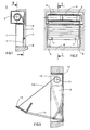
- FIGs 1 and 2 is shown, by way of example, a roller shutter 1 intended to close a doorway 2.
- This roller shutter is wound on a winding tube 3 driven in a known manner by a tubular motor 4 mounted in the tube 3.
- the tubular motor 4 is associated with a counting device 5 as described for example in French patent 2,525,832 or in patents FR 2 455 695 and 2 455 349.
- This counting device 5 is driven by the motor and includes two switches, one for each direction of rotation, actuated after a certain number of engine revolutions.
- Such tubular motor winding tube is described by example in patents FR 2 480 846 and 2 376 285.
- the roller shutter 1 is guided laterally by two slides 6 and its last blade is provided with two brackets stop 7 intended to come into abutment against the lower edge 8 and the upper edge 9 of the doorway.
- brackets stop 7 intended to come into abutment against the lower edge 8 and the upper edge 9 of the doorway.
- the "cassette" type blind shown in Figure 3 includes a fabric 10 which can be rolled up on a winding tube 11 similar to tube 3 and housed in a box 12 fixed in the doorway 13.
- the end of the fabric 10 is attached to a L-shaped part 14 itself attached to the end of two arms 15 articulated at the bottom of the embrasure 13, on each side thereof.
- the profiled part 14 just close the box 12 as shown in 14 '. This closure is only ensured if part 14 comes apply perfectly against the fixed part of the box 12.
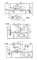
- the electric motor 4 (according to Figures 1 and 2) is a single-phase motor asynchronous phase shift capacitor. He is represented by its main winding E1 and its winding auxiliary E2 and here it includes two phase shift capacitors C3 and C4, capacitor C4 can be connected in parallel to C3 by means of a contact x.
- the capacity of C3 + C4 is calculated from to allow the engine to turn to torque nominal. When only C3 is connected, the engine runs at reduced torque.
- the counting device 5 comprises two units of counting (as described in the cited patents above) kinematically linked to the winding tube 3.
- the switch of the counting unit working in rise is replaced by an IM reverser activated when the blind reaches a memorized position when climbing in the counting unit, position corresponding to a position of profile 14 before coming into abutment against the box 12.
- the other counting unit, controlling the lowering the blind is fitted with a conventional switch ID.
- One of the terminals of the IM inverter common at contacts 1 and 2 is electrically connected to the self-powered terminal corresponding to "upward direction" a PC control point while one of the terminals of the ID switch is electrically connected to the self-powered terminal corresponding to the "direction" button descent "of this PC control point.
- P and N denote conventionally the phase and neutral of a feed single phase.
- M the conductor connected to the direction button rise and by D the conductor connected to the direction button descent.
- the other terminal of the ID switch is connected to the auxiliary winding E2 and the other terminal of the inverter IM is connected, via point common of a change-over contact x which can switch from one position 1 to position 2, at the main winding E1 of the engine.
- Terminal 2 of the change-over contact x is connected to one of the terminals of the IM inverter.
- This device also includes a timer module TP including a rectifier consisting of a bridge diodes D1 and a smoothing capacitor C1 and connected at the common point of the terminals of x and IM, a divisor voltage R1, R2, a C2 charge capacitor connected parallel to the resistor R2, a resistor R3 in series with a relay X and a transistor T1 connected in parallel at relay X, the base of transistor T1 being connected to the midpoint of the voltage divider R1, R2 at through a Zener D2 diode. R3 limits the current in relay X and in transistor T1. When the module time delay is switched on, the alternating voltage is rectified through the diode bridge D1 and of C1 and the capacitor C2 gradually charges at through R1.
- a timer module TP including a rectifier consisting of a bridge diodes D1 and a smoothing capacitor C1 and connected at the common point of the terminals of x and IM, a divisor voltage R1, R2, a C2 charge capacitor
- Zener diode D2 remains blocked until that the charge of C2 is sufficient for the voltage Zener appears at its terminals. As long as the Zener diode D2 is blocked, transistor T1 is blocked and the relay X is supplied with sufficient voltage to make contact x. When the Zener tension is reached, the Zener diode D2 turns on. The base transistor T1 is then supplied and T1 conducts, short-circuiting relay X. Contact x is then released. The charging time of C2 is calculated so to be a little longer than the time required to blind to move from the memorized top breakpoint up to the stop.
- This timer module could be replaced by any monostable or analog timing module known.
- the device shown operates as follows: the second counting unit memorizes the breakpoint "unrolled blind”. It is set to activate the ID switch when the blind is in the position desired course.
- the first counting unit memorizes the stop point "store returned" and it is set to activate the IM inverter a time before the closing profile 14 is in abutment on box 12, this time being lower than that provided by the timer module.
- the counting device is at the stop point "blind unrolled" and the ID switch is open. IM is closed on position 1 and contact x is at rest on the position 1.
- phase P is connected directly to the motor winding E1 and via capacitors C3 + C4 at winding E2.
- Engine can then supply its nominal torque.
- the counting device having left the point stored low, the ID switch closes.
- the counting activates the IM inverter and its contact goes from position 1 to position 2.
- Capacitor C4 is switched off and the auxiliary winding E2 is supplied only through capacitor C3.
- the engine provides reduced torque.
- the capacity C2 charges.
- the blind rolls up at reduced torque and the closing profile 14 abuts to close the box 12.
- the Zener diode D2 conducts, transistor T1 is conducting and contact x drops back to position 1.
- the motor is not more powered.
- the diagram shown in Figure 4 can be used as is to order the roller shutter shown in Figures 1 and 2, i.e. to bring safely the brackets 7 abutting against the upper edge 9 of the doorway.
- Figure 5 shows a second embodiment in which the timer is triggered so different.
- the timer module TP ' comprises a first diode D1 whose anode is connected to the neutral N of the sector and a second diode D'1 whose anode is connected to a resistor R'D connected in parallel to the phase shift capacitor C4.
- the diode D1 is in series with a current limiting resistor R3 itself in series with a transistor T2 whose emitter is connected to the conductor M through a resistor R5.
- the diode D'1 is connected to the base of the transistor T2 through two resistors R1 and R4, the common point of which is connected to the electrolytic capacitor C2.
- relay X Between the collector and the emitter of transistor T2 is connected a relay X, one of the terminals of which is connected to the conductor "Ascent" M through a break contact x and a resistance R5 parallel to the contact x and the other terminal is connected to the sector neutral through the resistor R3 of the diode D1.
- An electrolytic capacitor C'1 is also connected parallel to relay X and its normally closed contact x .
- IM switch is in series with capacitor C4 and a working contact x of relay X intended to connect two terminals of the "Climb" driver M.
- the operation of the device represented in FIG. 5 is as follows: when the "Up" button is activated at the control point PC, a voltage V1 causes the supply of the relay X through the diode D1 and the resistor R3, first under high voltage, then under reduced voltage, through resistor R5, after opening the normally open contact x .
- the conduction threshold of transistor T2 therefore becomes V1 x R5 / (R5 + X + R3), X representing the value of the resistance of relay X.
- the value of the conduction threshold is set between 5 and 10 V, for example by choosing R5.
- R3 has the function of limiting the current through the transistor T2. With the contact x closed, the main winding E1 is supplied directly and, with the switch IM closed, the auxiliary winding E2 is supplied through (C3 + C4).
- the motor supplies its nominal torque.
- the counting unit opens the IM switch and the winding E2 is now only supplied through the capacitor C3.
- the motor provides reduced torque and the blind continues to wind, then comes to a stop as in the previous case.
- Opening the IM switch causes a voltage V2 to appear on the terminal of the IM switch connected to the capacitor C4.
- the capacitor C2 then gradually charges through R1 and the diode D'1.
- this transistor T2 conducts, short-circuiting the relay X whose armature falls back. Its rest contact x closes allowing capacitor C2 to discharge.
- the voltage across its terminals drops to around 0.6 V.
- Maintaining the transistor T2 in the conductive state is ensured through the diode D'1 and the resistors R'D, R1 and R4, R'D having the function of allow the passage of the supply current from the base of transistor T2 once the switch IM is open.
- R4 is used to limit the intensity of the current through the transistor during the discharge of the capacitor C2.
- this last mode of execution presents several advantages which are the use of simple micro-contacts and breaking performance / inherently better aperture than a inexpensive relay which does not support this function well a capacitive power loop, better bonding / take-off of the relay, by positive reaction, a duration of timing almost independent of the mains voltage and immediate resetting of the timer by discharging the capacitor C2, allowing consecutive uses.
- FIG. 6 represents an alternative embodiment of the mode according to FIG. 5.
- This variant differs of the previous one in that the IM switch, the capacitor C4 and resistance R'D are arranged in parallel between the two windings E1 and E2 of the motor and the conductor "Climb", so that the motor is powered at reduced voltage after opening of the IM switch.
- This variant is also equipped an electric brake F blocking in the absence of current. For the rest the operation of this variant is identical to the embodiment shown in the figure 5.
- phase shift capacitor C'3 is dimensioned so that the motor runs at its nominal torque when this capacitor is on.
- Capacitor C4 is replaced here by a capacitor C'4 which can be inserted on the conductor of "Climb" M.
- the device includes a rotor detection module blocked RB consisting of a diode bridge D'1, a resistor current limiter R'3, of a capacitor smoothing C'2 and a relay X '.
- the diode bridge D'1 is connected to the terminals of the phase shift capacitor C'3.
- the device further comprises an electromagnetic brake F working by default current and a relay Connected to the "Climb" driver M.
- Relay X ' has two working contacts x'1 and x'2.
- Relay Y has two working contacts y1 and y2 and one break contact y .
- This device works as follows: when the button "mounted” and actuated at the PC control point, the relay It is supplied with power and its contacts change state.
- the winding main motor E1 is connected directly in phase P and the auxiliary winding E2 is connected to the phase by the capacitor C'3.
- the engine provides sound nominal torque.
- a voltage existing across the capacitor C'3, the blocked rotor detection module RB is supplied and relay X 'is energized. His contacts change state and brake F is supplied through contacts x'1 and y2.
- the IM inverter moves from the position 1 at position 2.
- Winding E1 is then supplied through capacitor C'4 and contacts x'2 and y1.
- the capacitor C'4 causes a drop of voltage on the motor windings and the motor is therefore supplied at reduced voltage.
- FIG 8. An example of execution of the corresponding command scheme is shown in Figure 8.
- the device includes a TP time module similar to that of Figure 4 and an auxiliary relay Y connected as in the previous case on the conductor "mounted".
- the device also includes an F brake working current default.
- the engine is of standard type.
- this device is as follows: the door being in the high position, if the user actuates the "descent" button at the control point, the auxiliary winding E2 of the motor is supplied directly through the inverter ID which is not actuated, while the main winding El is supplied through the phase shift capacitor C.
- the brake F is supplied through ID and the contacts x and y .
- the engine runs at reduced torque and the door is driven.
- the reverser ID is activated and the motor supply is interrupted.
- the inverter ID having moved to position 2, the timer module TP is then supplied and the relay X is energized. Brake F is then supplied by reverser ID and contact x.
- the door can therefore continue its descent "freewheeling" until it comes to a stop.
- the relay X is short-circuited and its armature drops.
- Brake F is then no longer supplied and brakes.
- FIG. 9 This diagram is a combination of the diagrams shown in Figures 4 and 8.
- the phase shift of the motor phases is obtained by a first capacitor C3 and a second capacitor C4 in parallel with C3, cut out by the relay X of the TP time module.
- the two units up and down counters are equipped with an inverter IM, respectively ID.
- IM inverter
- the door is in the closed (low) position if the user press the "Up” button at the control point, relay Y is energized and its contacts y1 and y2 close.
- the main winding E1 is then supplied directly through IM and y1, while by the same path the auxiliary winding E2 is supplied through the two capacitors C3 and C4, the contact x2 being closed.
- the motor then runs at its nominal torque.
- the inverter IM moves to position 2, which has the effect of feeding the TP time module.
- Relay X attracts and his contacts change state.
- the engine is then powered through IM in position 2 and the contacts x, y2 and y1.
- Capacitor C4 being cut off by opening of contact x2, motor turns to torque reduced.
- relay X drops out. Opening contact x simultaneously cuts off the power motor and brake F.
- Figure 10 illustrates, in diagram form, a use of the device as a safety device.
- This diagram represents the approximate pace the available effort margin E depending on the distance d traveled by a trained body, for example a door or gate.
- the available torque is the nominal torque of the motor.
- the resistance of the door is important and the margin of effort available to stop the door is weak. Then, resistance to door movement decreases and the margin of effort available increases, but before it does not reach the maximum acceptable effort margin Emax, the mechanical means for measuring the displacement of the door cause the power to the torque motor reduced.
Landscapes
- Engineering & Computer Science (AREA)
- Structural Engineering (AREA)
- Power Engineering (AREA)
- Physics & Mathematics (AREA)
- General Physics & Mathematics (AREA)
- Automation & Control Theory (AREA)
- Architecture (AREA)
- Civil Engineering (AREA)
- Human Computer Interaction (AREA)
- Manufacturing & Machinery (AREA)
- Operating, Guiding And Securing Of Roll- Type Closing Members (AREA)
- Stopping Of Electric Motors (AREA)
- Length Measuring Devices With Unspecified Measuring Means (AREA)
- Control Of Electric Motors In General (AREA)
- Electric Propulsion And Braking For Vehicles (AREA)
- Motorcycle And Bicycle Frame (AREA)
- Testing Of Balance (AREA)
- Programmable Controllers (AREA)
- Control Of Position Or Direction (AREA)
- Blinds (AREA)
- Power-Operated Mechanisms For Wings (AREA)
Description
Claims (13)
- Dispositif d'entraínement d'un corps (1;14) au moyen d'un moteur électrique, comprenant des moyens mécaniques (5) de mesure du déplacement dudit corps liés cinématiquement audit corps et équipés d'interrupteurs (ID,IM) actionnés pas lesdits moyens mécaniques de mesure en certains points du trajet dudit corps, caractérisé en ce qu'il comprend des moyens pour initialiser un mode particulier de fonctionnement du moteur mis en action par l'actionnement de l'un au moins desdits interrupteurs (ID,IM).
- Dispositif selon la revendication 1, caractérisé en ce que les moyens d'initialisation comprennent des moyens d'alimentation du moteur à couple réduit pendant une durée temporisée (TP, x, C4, figure 4; TP', x, C3, figure 5).
- Dispositif selon la revendication 1, caractérisé en ce que les moyens d'initialisation comprennent des moyens d'alimentation du moteur à tension réduite pendant une durée temporisée (TP', x, C'4, figure 6).
- Dispositif selon la revendication 1, caractérisé en ce que les moyens d'initialisation comprennent des moyens d'alimentation du moteur à tension réduite (RB, x'2, C'4) et en ce qu'il comprend en outre des moyens de détection (RB) du blocage du rotor du moteur coupant l'alimentation du moteur lorsqu'un tel blocage est détecté.
- Dispositif selon la revendication 4, dans lequel le moteur est un moteur asynchrone monophasé à condensateur de déphasage, caractérisé en ce que les moyens de détection du blocage du rotor sont constitués d'un relais (X') alimenté, par l'intermédiaire d'un circuit redresseur, par une tension prise aux bornes du condensateur de déphasage (C'3) du moteur.
- Dispositif selon la revendication 1, comprenant un frein fonctionnant par défaut de courant, caractérisé en ce que les moyens d'initialisation comprennent des moyens (ID) de coupure instantanée de l'alimentation du moteur et des moyens temporisés de coupure (TP, x) de l'alimentation du frein (F).
- Dispositif d'entraínement selon la revendication 1, dans lequel ledit corps est entraíné en montée et en descente et les moyens mécaniques de mesure du déplacement sont équipés d'un interrupteur correspondant à un point d'arrêt haut et d'un interrupteur correspondant à un point d'arrêt bas, et comprenant en outre un frein (F) fonctionnant par défaut de courant, caractérisé en ce que lesdits interrupteurs sont constitués d'inverseurs (IM, ID), que les moyens d'initialisation comprennent des moyens d'alimentation du moteur à couple réduit pendant une durée temporisée, activés par l'inverseur de point d'arrêt haut (IM) et des moyens de coupure instantanée d'alimentation du moteur et de coupure temporisée d'alimentation du frein activés par l'inverseur de point d'arrêt bas (ID) (Figure 9).
- Dispositif selon la revendication 2, pour l'entraínement d'un objet entre un point bas et une butée haute, caractérisé en ce que l'un desdits interrupteurs est un inverseur (IM) actionné avant que l'objet, en montée, arrive contre la butée haute, et en ce qu'il comprend un circuit de temporisation (TP) mis sous tension par ledit inverseur (IM).
- Dispositif selon la revendication 2, pour l'entraínement d'un objet entre un point bas et une butée haute, caractérisé en ce que les moyens mécaniques de mesure du déplacement sont réglés de telle manière, qu'en montée, l'un des interrupteurs (IM) soit actionné avant que l'objet arrive en butée et en ce qu'il comprend un moyen électronique de temporisation (TP') mis sous tension par l'actionnement du bouton de commande "montée" et déclenché par ledit interrupteur (IM) de manière à initialiser la temporisation.
- Dispositif selon la revendication 6 ou 7, caractérisé en ce que les moyens de temporisation (TP) comprennent un relais (X) excité durant la temporisation de manière à maintenir, par l'un de ses contacts (x) l'alimentation du frein (F) pendant la temporisation.
- Dispositif selon la revendication 10, pour l'entraínement d'un objet entre un point bas et un point haut et inversement ou horizontalement entre une position ouverte et fermée, caractérisé en ce qu'il comprend en outre un second relais (Y) excité en montée et assurant par ses contacts l'alimentation du frein (F) et du moteur en montée, respectivement en ouverture.
- Dispositif selon la revendication 7, caractérisé en ce qu'il comprend un circuit de temporisation (TP) comprenant un relais (X) excité pendant la temporisation et assurant, par ses contacts, l'alimentation du moteur à couple réduit en montée et l'alimentation du frein (F) pendant la temporisation, et qu'il comprend un second relais (Y) excité en montée et assurant, en montée, par ses contacts, l'alimentation du frein (F) et l'alimentation du moteur à couple nominal jusqu'à l'actionnement de l'interrupteur du point d'arrêt haut (IM), c'est-à-dire avant l'initialisation de la temporisation.
- Dispositif d'entraínement selon l'une des revendications 2, 3, 4, 5, 6 ou 11, caractérisé en ce que les moyens mécaniques de mesure du déplacement sont réglés de telle manière qu'au moins l'un de ses interrupteurs soit actionné avant que la différence entre l'effort exercé par le moteur et l'effort résistant à l'avancement dudit corps atteigne une valeur déterminée.
Applications Claiming Priority (2)
| Application Number | Priority Date | Filing Date | Title |
|---|---|---|---|
| FR9402397A FR2717016B1 (fr) | 1994-03-02 | 1994-03-02 | Dispositif d'entraînement par moteur électrique comprenant des moyens de mesure du déplacement du corps entraîné. |
| FR9402397 | 1994-03-02 |
Publications (2)
| Publication Number | Publication Date |
|---|---|
| EP0671542A1 EP0671542A1 (fr) | 1995-09-13 |
| EP0671542B1 true EP0671542B1 (fr) | 2000-05-10 |
Family
ID=9460590
Family Applications (1)
| Application Number | Title | Priority Date | Filing Date |
|---|---|---|---|
| EP95810112A Expired - Lifetime EP0671542B1 (fr) | 1994-03-02 | 1995-02-20 | Dispositif d'entraínement par moteur électrique comprenant des moyens de mesure du déplacement du corps entraíné |
Country Status (7)
| Country | Link |
|---|---|
| US (1) | US5621295A (fr) |
| EP (1) | EP0671542B1 (fr) |
| JP (1) | JP3490530B2 (fr) |
| AT (1) | ATE192825T1 (fr) |
| DE (1) | DE69516742T2 (fr) |
| ES (1) | ES2079343T3 (fr) |
| FR (1) | FR2717016B1 (fr) |
Families Citing this family (18)
| Publication number | Priority date | Publication date | Assignee | Title |
|---|---|---|---|---|
| ES2214518T5 (es) † | 1995-10-28 | 2011-04-13 | Elero Gmbh | Procedimiento para el accionamiento de marquesinas o similares accionadas con motor eléctrico. |
| DE59709367D1 (de) * | 1996-05-22 | 2003-04-03 | Becker Antriebe Gmbh | Steuerung für Antriebe von Toren |
| FR2814298B1 (fr) | 2000-09-15 | 2002-12-06 | Somfy | Procede de commande d'un moteur electrique entrainant un corps en translation |
| US6751909B2 (en) * | 2001-02-06 | 2004-06-22 | The Stanley Works | Automatic door control system |
| ITVI20020047A1 (it) * | 2002-03-19 | 2003-09-19 | Fitem Srl | Dispositivo di controllo per gruppi di avvolgimento/svolgimento di elementi flessibili |
| US6798158B2 (en) | 2002-10-22 | 2004-09-28 | Dometic Corporation | Wind sensing awning control |
| FR2879047B1 (fr) * | 2004-12-07 | 2007-09-14 | Somfy Sas | Procede d'alimentation d'un moteur de manoeuvre d'un volet roulant et dispositif de volet roulant motorise |
| US7389806B2 (en) * | 2005-02-24 | 2008-06-24 | Lawrence Kates | Motorized window shade system |
| US20060232234A1 (en) * | 2005-04-01 | 2006-10-19 | Newman Robert C Jr | Motorized roller tube system having dual-mode operation |
| US20060232233A1 (en) * | 2005-04-01 | 2006-10-19 | Adams Jason O | Drive assembly for a motorized roller tube system |
| FR2899984B1 (fr) * | 2006-04-13 | 2008-10-03 | Somfy Soc Par Actions Simplifi | Procede d'initialisation d'un volet roulant motorise |
| US20080266742A1 (en) * | 2007-04-30 | 2008-10-30 | Watlow Electric Manufacturing Company | Apparatus and method for increasing switching life of electromechanical contacts in a hybrid power switching device |
| US20090308543A1 (en) * | 2008-06-13 | 2009-12-17 | Lawrence Kates | Motorized window shade system and mount |
| FR2955956B1 (fr) | 2010-02-04 | 2013-06-28 | Somfy Sas | Capteur de mouvement pour dispositif domotique. |
| CN102278277B (zh) * | 2011-06-24 | 2013-04-17 | 湘潭世通电气有限公司 | 一种风电轮毂安全逻辑控制装置 |
| DE102019220491B4 (de) * | 2019-12-20 | 2022-03-31 | Dometic Sweden Ab | Fenstersonnenblendenvorrichtung und fahrzeug mit fenstersonnenblendenvorrichtung |
| DE102019220488B4 (de) * | 2019-12-20 | 2022-02-03 | Dometic Sweden Ab | Fenstersonnenblendenvorrichtung und Fahrzeug mit einer Sonnenblendenvorrichtung |
| DE102019220490B4 (de) * | 2019-12-20 | 2024-09-26 | Dometic Sweden Ab | Fenstersonnenblendenvorrichtung und fahrzeug mit einer fenstersonnenblendenvorrichtung |
Family Cites Families (9)
| Publication number | Priority date | Publication date | Assignee | Title |
|---|---|---|---|---|
| US3183423A (en) * | 1961-09-22 | 1965-05-11 | Square D Co | Limit control for motors |
| US3551740A (en) * | 1968-05-31 | 1970-12-29 | Square D Co | Limit control for an alternating current motor |
| GB2113028B (en) * | 1981-12-31 | 1986-09-03 | Burroughs Corp | Data disc rotating systems |
| DE3333119A1 (de) * | 1983-09-14 | 1985-03-28 | SWF Auto-Electric GmbH, 7120 Bietigheim-Bissingen | Schaltanordnung fuer einen drehrichtungsumkehrbaren elektrischen motor |
| DE3803119A1 (de) * | 1988-02-03 | 1989-08-17 | Schwenk Kg Theben Werk | Elektronische drehrichtungsteuervorrichtung fuer einen wechselstrommotor |
| JPH079127B2 (ja) * | 1989-08-17 | 1995-02-01 | ワイケイケイ株式会社 | 自動ドアの開閉制御方法 |
| US4958112A (en) * | 1989-09-27 | 1990-09-18 | Zerillo Michael A | Drapery actuator operated by lamp timer and hand-held wireless remote control |
| FR2671129B1 (fr) * | 1990-12-28 | 1993-04-09 | Sompy | Dispositif de commande d'un moteur de store ou similaires a deux sens de rotation. |
| US5170108A (en) * | 1991-01-31 | 1992-12-08 | Daylighting, Inc. | Motion control method and apparatus for motorized window blinds and and the like |
-
1994
- 1994-03-02 FR FR9402397A patent/FR2717016B1/fr not_active Expired - Lifetime
-
1995
- 1995-02-08 US US08/385,272 patent/US5621295A/en not_active Expired - Fee Related
- 1995-02-20 EP EP95810112A patent/EP0671542B1/fr not_active Expired - Lifetime
- 1995-02-20 DE DE69516742T patent/DE69516742T2/de not_active Expired - Lifetime
- 1995-02-20 ES ES95810112T patent/ES2079343T3/es not_active Expired - Lifetime
- 1995-02-20 AT AT95810112T patent/ATE192825T1/de not_active IP Right Cessation
- 1995-03-02 JP JP04316595A patent/JP3490530B2/ja not_active Expired - Fee Related
Also Published As
| Publication number | Publication date |
|---|---|
| EP0671542A1 (fr) | 1995-09-13 |
| DE69516742T2 (de) | 2000-11-23 |
| JPH07269254A (ja) | 1995-10-17 |
| ATE192825T1 (de) | 2000-05-15 |
| FR2717016B1 (fr) | 1996-05-15 |
| JP3490530B2 (ja) | 2004-01-26 |
| FR2717016A1 (fr) | 1995-09-08 |
| ES2079343T1 (es) | 1996-01-16 |
| ES2079343T3 (es) | 2000-08-01 |
| DE69516742D1 (de) | 2000-06-15 |
| US5621295A (en) | 1997-04-15 |
Similar Documents
| Publication | Publication Date | Title |
|---|---|---|
| EP0671542B1 (fr) | Dispositif d'entraínement par moteur électrique comprenant des moyens de mesure du déplacement du corps entraíné | |
| EP0057338B1 (fr) | Boîtier de commande pour moteur d'entraînement de panneau coulissant d'un véhicule, notamment pour lève-glace | |
| EP0784146B1 (fr) | Installation de fermeture ou de protection solaire motorisée | |
| EP1845218A2 (fr) | Installation de store motorisée et procédé de commande d'une telle installation | |
| EP1845217B1 (fr) | Procédé de commande et installation de store commandée par ce procédé | |
| EP3292262B1 (fr) | Procédés de configuration et de commande en fonctionnement d'un dispositif d'entraînement motorisé d'une installation domotique, dispositif d'entraînement motorisé et installation associés | |
| EP0573388B1 (fr) | Dispositif générateur de signaux caractéristiques du déplacement d'un moyen de fermeture | |
| FR2779879A1 (fr) | Dispositif de commande de l'arret d'un produit d'occultation motorise | |
| EP0819204B1 (fr) | Porte de manutention avec systeme de securite | |
| EP3470616B1 (fr) | Procede de reglage d'une installation de volet roulant munie d'un verrou et installation de volet roulant | |
| EP1093947B1 (fr) | Store à enrouler motorisé, à moyens de solidarisation sélective du tube d'enroulement aux moyens de motorisation | |
| EP1843004B1 (fr) | Profilé d'extrémité de tablier de dispositif de protection | |
| FR2740824A1 (fr) | Installation de fermeture ou de protection solaire motorisee | |
| EP1530284B1 (fr) | Procédé et dispositif de régulation de la vitesse de rotation d'un moteur de volet roulant | |
| FR2835877A1 (fr) | Dispositif d'entrainement electrique d'un volet roulant ou d'un store | |
| BE1009697A3 (fr) | Dispositif comprenant un element enroulable mobile entre deux positions extremes pour l'une au moins desquelles une fin de course provoque l'arret d'un moteur, application aux stores. | |
| WO2025141104A1 (fr) | Procédé de fonctionnement d'un actionneur électromécanique d'une installation de fermeture, d'occultation ou de protection solaire | |
| EP3470617B1 (fr) | Procede de commande automatisee d'une installation de volet roulant et installation d'ecran motorise | |
| FR3087474A1 (fr) | Procede de controle d'un systeme d'actionnement d'un premier et d'un second ecrans et systeme d'actionnement | |
| FR2769765A1 (fr) | Dispositif d'occultation de fenetres a moteur electrique et organe de commande pre-cables en usine | |
| EP1153192A1 (fr) | Dispositif pour arreter en fonction d'un couple de declenchement variable, un moteur entrainant un tube d'enroulement d'un volet roulant | |
| EP3128100A1 (fr) | Procédé de commande d'une installation de store motorisée | |
| EP2166192B1 (fr) | Procédé d'actionnement d'un dispositif de fermeture et d'ouverture d'un ouvrant | |
| EP1612360A1 (fr) | Dispositif de commande d'une baie coulissante motorisée, notamment pour une cabine de conduite d'un matériel ferroviaire ou similaire | |
| FR2699824A1 (fr) | Barrière coupe-feu de sécurité. |
Legal Events
| Date | Code | Title | Description |
|---|---|---|---|
| PUAI | Public reference made under article 153(3) epc to a published international application that has entered the european phase |
Free format text: ORIGINAL CODE: 0009012 |
|
| AK | Designated contracting states |
Kind code of ref document: A1 Designated state(s): AT BE CH DE ES GB IT LI NL SE |
|
| REG | Reference to a national code |
Ref country code: ES Ref legal event code: BA2A Ref document number: 2079343 Country of ref document: ES Kind code of ref document: T1 |
|
| 17P | Request for examination filed |
Effective date: 19960117 |
|
| 17Q | First examination report despatched |
Effective date: 19961230 |
|
| GRAG | Despatch of communication of intention to grant |
Free format text: ORIGINAL CODE: EPIDOS AGRA |
|
| GRAG | Despatch of communication of intention to grant |
Free format text: ORIGINAL CODE: EPIDOS AGRA |
|
| GRAH | Despatch of communication of intention to grant a patent |
Free format text: ORIGINAL CODE: EPIDOS IGRA |
|
| GRAH | Despatch of communication of intention to grant a patent |
Free format text: ORIGINAL CODE: EPIDOS IGRA |
|
| GRAA | (expected) grant |
Free format text: ORIGINAL CODE: 0009210 |
|
| AK | Designated contracting states |
Kind code of ref document: B1 Designated state(s): AT BE CH DE ES GB IT LI NL SE |
|
| PG25 | Lapsed in a contracting state [announced via postgrant information from national office to epo] |
Ref country code: GB Free format text: LAPSE BECAUSE OF FAILURE TO SUBMIT A TRANSLATION OF THE DESCRIPTION OR TO PAY THE FEE WITHIN THE PRESCRIBED TIME-LIMIT Effective date: 20000510 Ref country code: AT Free format text: LAPSE BECAUSE OF FAILURE TO SUBMIT A TRANSLATION OF THE DESCRIPTION OR TO PAY THE FEE WITHIN THE PRESCRIBED TIME-LIMIT Effective date: 20000510 |
|
| REF | Corresponds to: |
Ref document number: 192825 Country of ref document: AT Date of ref document: 20000515 Kind code of ref document: T |
|
| REG | Reference to a national code |
Ref country code: CH Ref legal event code: EP |
|
| REF | Corresponds to: |
Ref document number: 69516742 Country of ref document: DE Date of ref document: 20000615 |
|
| REG | Reference to a national code |
Ref country code: CH Ref legal event code: NV Representative=s name: BUGNION S.A. |
|
| ITF | It: translation for a ep patent filed | ||
| REG | Reference to a national code |
Ref country code: ES Ref legal event code: FG2A Ref document number: 2079343 Country of ref document: ES Kind code of ref document: T3 |
|
| PG25 | Lapsed in a contracting state [announced via postgrant information from national office to epo] |
Ref country code: SE Free format text: LAPSE BECAUSE OF FAILURE TO SUBMIT A TRANSLATION OF THE DESCRIPTION OR TO PAY THE FEE WITHIN THE PRESCRIBED TIME-LIMIT Effective date: 20000810 |
|
| GBV | Gb: ep patent (uk) treated as always having been void in accordance with gb section 77(7)/1977 [no translation filed] |
Effective date: 20000510 |
|
| PLBE | No opposition filed within time limit |
Free format text: ORIGINAL CODE: 0009261 |
|
| STAA | Information on the status of an ep patent application or granted ep patent |
Free format text: STATUS: NO OPPOSITION FILED WITHIN TIME LIMIT |
|
| 26N | No opposition filed | ||
| PGFP | Annual fee paid to national office [announced via postgrant information from national office to epo] |
Ref country code: ES Payment date: 20100223 Year of fee payment: 16 |
|
| PGFP | Annual fee paid to national office [announced via postgrant information from national office to epo] |
Ref country code: IT Payment date: 20100227 Year of fee payment: 16 |
|
| PG25 | Lapsed in a contracting state [announced via postgrant information from national office to epo] |
Ref country code: IT Free format text: LAPSE BECAUSE OF NON-PAYMENT OF DUE FEES Effective date: 20110220 |
|
| REG | Reference to a national code |
Ref country code: ES Ref legal event code: FD2A Effective date: 20120411 |
|
| PG25 | Lapsed in a contracting state [announced via postgrant information from national office to epo] |
Ref country code: ES Free format text: LAPSE BECAUSE OF NON-PAYMENT OF DUE FEES Effective date: 20110221 |
|
| PGFP | Annual fee paid to national office [announced via postgrant information from national office to epo] |
Ref country code: CH Payment date: 20130306 Year of fee payment: 19 Ref country code: DE Payment date: 20130225 Year of fee payment: 19 |
|
| PGFP | Annual fee paid to national office [announced via postgrant information from national office to epo] |
Ref country code: NL Payment date: 20130222 Year of fee payment: 19 |
|
| PGFP | Annual fee paid to national office [announced via postgrant information from national office to epo] |
Ref country code: BE Payment date: 20130301 Year of fee payment: 19 |
|
| BERE | Be: lapsed |
Owner name: *SOMFY Effective date: 20140228 |
|
| REG | Reference to a national code |
Ref country code: DE Ref legal event code: R119 Ref document number: 69516742 Country of ref document: DE |
|
| REG | Reference to a national code |
Ref country code: NL Ref legal event code: V1 Effective date: 20140901 |
|
| REG | Reference to a national code |
Ref country code: CH Ref legal event code: PL |
|
| PG25 | Lapsed in a contracting state [announced via postgrant information from national office to epo] |
Ref country code: CH Free format text: LAPSE BECAUSE OF NON-PAYMENT OF DUE FEES Effective date: 20140228 Ref country code: NL Free format text: LAPSE BECAUSE OF NON-PAYMENT OF DUE FEES Effective date: 20140901 Ref country code: LI Free format text: LAPSE BECAUSE OF NON-PAYMENT OF DUE FEES Effective date: 20140228 |
|
| REG | Reference to a national code |
Ref country code: DE Ref legal event code: R119 Ref document number: 69516742 Country of ref document: DE Effective date: 20140902 |
|
| PG25 | Lapsed in a contracting state [announced via postgrant information from national office to epo] |
Ref country code: DE Free format text: LAPSE BECAUSE OF NON-PAYMENT OF DUE FEES Effective date: 20140902 Ref country code: BE Free format text: LAPSE BECAUSE OF NON-PAYMENT OF DUE FEES Effective date: 20140228 |