EP0671222A2 - Absiebvorrichtung für Kompost - Google Patents
Absiebvorrichtung für Kompost Download PDFInfo
- Publication number
- EP0671222A2 EP0671222A2 EP95102150A EP95102150A EP0671222A2 EP 0671222 A2 EP0671222 A2 EP 0671222A2 EP 95102150 A EP95102150 A EP 95102150A EP 95102150 A EP95102150 A EP 95102150A EP 0671222 A2 EP0671222 A2 EP 0671222A2
- Authority
- EP
- European Patent Office
- Prior art keywords
- belt
- sieve
- sieve belt
- effective
- screening device
- Prior art date
- Legal status (The legal status is an assumption and is not a legal conclusion. Google has not performed a legal analysis and makes no representation as to the accuracy of the status listed.)
- Granted
Links
- 239000002361 compost Substances 0.000 title claims abstract description 4
- 238000012216 screening Methods 0.000 title claims description 12
- 239000000463 material Substances 0.000 claims abstract description 14
- 239000010815 organic waste Substances 0.000 claims description 2
- 239000002985 plastic film Substances 0.000 claims description 2
- 229920006255 plastic film Polymers 0.000 claims description 2
- 230000000630 rising effect Effects 0.000 claims description 2
- 238000010079 rubber tapping Methods 0.000 claims description 2
- 239000000945 filler Substances 0.000 claims 1
- 238000010009 beating Methods 0.000 abstract 2
- 230000003134 recirculating effect Effects 0.000 abstract 1
- 238000011161 development Methods 0.000 description 3
- 230000018109 developmental process Effects 0.000 description 3
- 238000009264 composting Methods 0.000 description 1
- 238000010276 construction Methods 0.000 description 1
- 238000000034 method Methods 0.000 description 1
- 230000002093 peripheral effect Effects 0.000 description 1
- 239000004033 plastic Substances 0.000 description 1
Images
Classifications
-
- B—PERFORMING OPERATIONS; TRANSPORTING
- B07—SEPARATING SOLIDS FROM SOLIDS; SORTING
- B07B—SEPARATING SOLIDS FROM SOLIDS BY SIEVING, SCREENING, SIFTING OR BY USING GAS CURRENTS; SEPARATING BY OTHER DRY METHODS APPLICABLE TO BULK MATERIAL, e.g. LOOSE ARTICLES FIT TO BE HANDLED LIKE BULK MATERIAL
- B07B13/00—Grading or sorting solid materials by dry methods, not otherwise provided for; Sorting articles otherwise than by indirectly controlled devices
- B07B13/14—Details or accessories
- B07B13/16—Feed or discharge arrangements
-
- B—PERFORMING OPERATIONS; TRANSPORTING
- B03—SEPARATION OF SOLID MATERIALS USING LIQUIDS OR USING PNEUMATIC TABLES OR JIGS; MAGNETIC OR ELECTROSTATIC SEPARATION OF SOLID MATERIALS FROM SOLID MATERIALS OR FLUIDS; SEPARATION BY HIGH-VOLTAGE ELECTRIC FIELDS
- B03B—SEPARATING SOLID MATERIALS USING LIQUIDS OR USING PNEUMATIC TABLES OR JIGS
- B03B9/00—General arrangement of separating plant, e.g. flow sheets
- B03B9/06—General arrangement of separating plant, e.g. flow sheets specially adapted for refuse
-
- B—PERFORMING OPERATIONS; TRANSPORTING
- B07—SEPARATING SOLIDS FROM SOLIDS; SORTING
- B07B—SEPARATING SOLIDS FROM SOLIDS BY SIEVING, SCREENING, SIFTING OR BY USING GAS CURRENTS; SEPARATING BY OTHER DRY METHODS APPLICABLE TO BULK MATERIAL, e.g. LOOSE ARTICLES FIT TO BE HANDLED LIKE BULK MATERIAL
- B07B1/00—Sieving, screening, sifting, or sorting solid materials using networks, gratings, grids, or the like
- B07B1/005—Transportable screening plants
-
- B—PERFORMING OPERATIONS; TRANSPORTING
- B07—SEPARATING SOLIDS FROM SOLIDS; SORTING
- B07B—SEPARATING SOLIDS FROM SOLIDS BY SIEVING, SCREENING, SIFTING OR BY USING GAS CURRENTS; SEPARATING BY OTHER DRY METHODS APPLICABLE TO BULK MATERIAL, e.g. LOOSE ARTICLES FIT TO BE HANDLED LIKE BULK MATERIAL
- B07B1/00—Sieving, screening, sifting, or sorting solid materials using networks, gratings, grids, or the like
- B07B1/10—Screens in the form of endless moving bands
-
- B—PERFORMING OPERATIONS; TRANSPORTING
- B07—SEPARATING SOLIDS FROM SOLIDS; SORTING
- B07B—SEPARATING SOLIDS FROM SOLIDS BY SIEVING, SCREENING, SIFTING OR BY USING GAS CURRENTS; SEPARATING BY OTHER DRY METHODS APPLICABLE TO BULK MATERIAL, e.g. LOOSE ARTICLES FIT TO BE HANDLED LIKE BULK MATERIAL
- B07B1/00—Sieving, screening, sifting, or sorting solid materials using networks, gratings, grids, or the like
- B07B1/46—Constructional details of screens in general; Cleaning or heating of screens
- B07B1/50—Cleaning
- B07B1/54—Cleaning with beating devices
-
- B—PERFORMING OPERATIONS; TRANSPORTING
- B07—SEPARATING SOLIDS FROM SOLIDS; SORTING
- B07B—SEPARATING SOLIDS FROM SOLIDS BY SIEVING, SCREENING, SIFTING OR BY USING GAS CURRENTS; SEPARATING BY OTHER DRY METHODS APPLICABLE TO BULK MATERIAL, e.g. LOOSE ARTICLES FIT TO BE HANDLED LIKE BULK MATERIAL
- B07B9/00—Combinations of apparatus for screening or sifting or for separating solids from solids using gas currents; General arrangement of plant, e.g. flow sheets
-
- C—CHEMISTRY; METALLURGY
- C05—FERTILISERS; MANUFACTURE THEREOF
- C05F—ORGANIC FERTILISERS NOT COVERED BY SUBCLASSES C05B, C05C, e.g. FERTILISERS FROM WASTE OR REFUSE
- C05F9/00—Fertilisers from household or town refuse
- C05F9/02—Apparatus for the manufacture
-
- Y—GENERAL TAGGING OF NEW TECHNOLOGICAL DEVELOPMENTS; GENERAL TAGGING OF CROSS-SECTIONAL TECHNOLOGIES SPANNING OVER SEVERAL SECTIONS OF THE IPC; TECHNICAL SUBJECTS COVERED BY FORMER USPC CROSS-REFERENCE ART COLLECTIONS [XRACs] AND DIGESTS
- Y02—TECHNOLOGIES OR APPLICATIONS FOR MITIGATION OR ADAPTATION AGAINST CLIMATE CHANGE
- Y02A—TECHNOLOGIES FOR ADAPTATION TO CLIMATE CHANGE
- Y02A40/00—Adaptation technologies in agriculture, forestry, livestock or agroalimentary production
- Y02A40/10—Adaptation technologies in agriculture, forestry, livestock or agroalimentary production in agriculture
- Y02A40/20—Fertilizers of biological origin, e.g. guano or fertilizers made from animal corpses
-
- Y—GENERAL TAGGING OF NEW TECHNOLOGICAL DEVELOPMENTS; GENERAL TAGGING OF CROSS-SECTIONAL TECHNOLOGIES SPANNING OVER SEVERAL SECTIONS OF THE IPC; TECHNICAL SUBJECTS COVERED BY FORMER USPC CROSS-REFERENCE ART COLLECTIONS [XRACs] AND DIGESTS
- Y02—TECHNOLOGIES OR APPLICATIONS FOR MITIGATION OR ADAPTATION AGAINST CLIMATE CHANGE
- Y02W—CLIMATE CHANGE MITIGATION TECHNOLOGIES RELATED TO WASTEWATER TREATMENT OR WASTE MANAGEMENT
- Y02W30/00—Technologies for solid waste management
- Y02W30/50—Reuse, recycling or recovery technologies
- Y02W30/52—Mechanical processing of waste for the recovery of materials, e.g. crushing, shredding, separation or disassembly
Definitions
- the invention relates to a portable screening device or a screening device for compost or all rotable organic waste materials which can be attached to other devices if required.
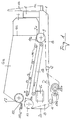
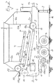
- FIG. 1 shows the new screening device as a system in a longitudinal section, largely schematically, and FIG. 2 shows a development of FIG. 1.
- the new screen system in its basic structure, consists of a frame or base frame 1 with attachment 1a, hydraulic drive system 4, 5 and screen box 6a.
- the bottom area of the screen box 6a is formed by a peripheral screen belt 8, with drive station 10, corresponding deflection rollers 9, 11 and tensioning roller 12, and immediately below the effective screen belt area 8a is a continuous or intermittent impact or vibrating device is provided, consisting for example of several, eccentrically or the like by a common drive rod 13. driven, distributed knockers 14. These knockers cause the material to be screened to "bounce" on the sieve plate, thereby counteracting clogging or smearing of the sieve plate.
- two discharge conveyors 15, 16 are arranged below the sieve belt 8a and tapping device 13, 14 for collecting 15 the material falling through the effective sieve belt region 8a and at right angles to it 16 for removing the material laterally outwards.
- Also important in the new device is the assignment of a so-called air classifier 17 with a scraper 18 and collecting trough including discharge belt 18a at the end of the effective belt area 8a above the drive roller 10 for removing scraps from plastic films.
- a swiveling sieve belt changing station 19a, 19b in the lower region of the base frame 1 ultimately allows the use of different large perforated or profiled sieve belts made of barbed wire mesh or plastic mats.
- the changing process takes place in such a way that the sieve plate that was last used is loosened at its connection point arranged transversely to the direction of travel and its end is wound onto the "empty spool" 19a, while at the same time the other end of the belt that is running the beginning of the new sieve belt from the supply station 19b with off and on the roller system.
- FIG. 2 which represents the new sieve as a movable system with a drawbar 1a, pivotable floor support 2 and running wheels 3, the special feature is the assignment of an essentially vertically directed feed chute 6, 6a to the effective sieve belt region 8a which is directed downwards by a Above the latter 8a, all-round scraper floor 7, which is provided with strips or ribs 7a and serves as a metering device, except for a material passage gap 6b between the scraper floor end and the adjacent filling shaft wall 6a. It is also important for both systems that the effective sieve belt area 8a runs slightly rising in the direction of rotation U and likewise the first discharge conveyor belt 15 arranged at a distance below it.
- the scraper floor 7 which runs at a horizontal distance "H" above the sieve belt 8a is then appropriately inclined in the same way.
Landscapes
- Engineering & Computer Science (AREA)
- Manufacturing & Machinery (AREA)
- Chemical & Material Sciences (AREA)
- Organic Chemistry (AREA)
- Fertilizers (AREA)
- Combined Means For Separation Of Solids (AREA)
- Fertilizing (AREA)
- Processing Of Solid Wastes (AREA)
Abstract
Description
- Die Erfindung betrifft nach dem Oberbegriff des Patentanspruches 1 eine ortsbewegliche oder an andere Geräte bei Bedarf anbaubare Absiebvorrichtung für Kompost bzw. alle rottefähigen organischen Abfallmaterialien.
- Es ist bekannt, daß vor allem bei der industriellen Kompostierung solcher Materialien von Zeit zu Zeit ein Umsetzen der Mieten mit möglichst gleichzeitiger Absiebung bereits fertigen Rottegutes erfolgen muß.
- Bekannte Absiebvorrichtungen hierfür haben allesamt bislang den Nachteil, daß sich die Siebböden durch das feuchte Material relativ rasch zusetzen.
Die Aufgabe der vorliegenden Erfindung ist daher darin zu sehen, eine geeignete Absiebvorrichtung zu schaffen, deren Siebboden durch geeigneten Aufbau und Zusatzmaßnahmen stets voll einsatzfähig bleibt. - Gelöst wird diese Aufgabe dabei durch die Merkmalskombination des Patentanspruches 1; die Unteransprüche beinhalten vorteilhafte Weiterbildungen und Details des neuen Grundsystems, das anhand einer Zeichnungsskizze im folgenden noch näher erläutert ist.
- Die Skizze zeigt in Fig. 1 weitestgehend schematisch die neue Siebvorrichtung als System im Längsschnitt und Fig. 2 eine Weiterbildung zu Fig. 1.
- In seinem Grundaufbau besteht das neue Siebsystem nach Fig. 1 aus einem Gestell bzw. Grundrahmen 1 mit Anbauvorrichtung 1a, hydraulischem Antriebssystem 4, 5 und Siebkasten 6a.
Der bodenseitige Bereich des Siebkastens 6a wird durch ein umlaufendes Siebband 8 gebildet, mit Antriebsstation 10, entsprechenden Umlenkrollen 9, 11 und Spannrolle 12, und unmittelbar unterhalb des wirksamen Siebbandbereichs 8a ist eine kontinuierlich bzw. absatzweise wirkende Schlag- oder Rütteleinrichtung vorgesehen, bestehend beispielsweise aus mehreren, durch eine gemeinsame Antriebsstange 13 exzentrisch o.ä. angetriebenen, verteilt liegenden Klopfern 14.
Diese Klopfer bewirken dabei, daß das abzusiebende Material auf dem Siebboden "hüpft", wodurch einem Zusetzen oder Verschmieren des Siebbodens entgegengewirkt wird. - Weiterhin sind unterhalb von Siebband 8a und Klopfeinrichtung 13, 14, zwei Austragförderer 15, 16, angeordnet zum Sammeln 15 des durch den wirksamen Siebbandbereich 8a fallenden Materials und rechtwinklig dazu 16 zum Abführen des Materials seitlich nach außen.
- Wichtig bei der neuen Vorrichtung ist zudem noch die Zuordnung eines sogenannten Windsichters 17 mit Abstreifer 18 und Sammelrinne samt Austragband 18a am Ende des wirksamen Bandbereichs 8a oberhalb der Antriebsrolle 10 zum Abführen von Fetzen aus Kunststoffolien.
- Die Anordnung einer einschwenkbaren Siebband-Wechselstation 19a, 19b im unteren Bereich des Grundrahmens 1 erlaubt letztlich noch die Verwendung von unterschiedlich groß gelochten oder profilierten Siebbändern aus Stacheldrahtgeflecht oder Kunststoffmatten. Der Wechselvorgang geht dabei derart vonstatten, daß der zuletzt im Einsatz gewesene Siebboden an seiner quer zur Laufrichtung angeordneten Verbindungsstelle gelöst und mit seinem Ende auf die "Leerspule" 19a aufgewickelt wird, während gleichzeitig das ablaufende andere Bandende den Anfang des neuen Siebbandes von der Vorratsstation 19b mit ab- und auf das Rollensystem aufzieht.
- Bei der Weiterbildung nach Fig. 2, die das neue Sieb als verfahrbares System mit Zugmaul 1a schwenkbarer Bodenstütze 2 und Laufrädern 3 darstellt, ist das besondere die Zuordnung eines im wesentlichen vertikal gerichteten Einfüllschachtes 6, 6a zum wirksamen Siebbandbereich 8a der nach unten hin durch einen oberhalb des letzteren 8a, umlaufenden, mit Leisten oder Rippen 7a besetzten, als Dosiereinrichtung dienenden Kratzboden 7 bis auf einen Material-Durchlaßspalt 6b zwischen Kratzbodenende und benachbarter Einfüllschachtwand 6a abgeschlossen ist.
Wichtig für beide Systeme ist zudem noch, daß der wirksame Siebbandbereich 8a in Umlaufrichtung U leicht ansteigend verläuft und ebenso das mit Abstand darunter angeordnete, erste Austragförderband 15. - Der mit Horizontalabstand "H" oberhalb des Siebbandes 8a verlaufende Kratzboden 7 ist dann sinnvollerweise in gleicher Art geneigt.
-
- 1
- Grundrahmen
- 1a
- Zugmaul ( Anbausystem )
- 2
- Stütze
- 3
- Laufrad
- 4
- hydraulischer Antrieb
- 5
- hydraulischer Antrieb
- 6
- Einfüllschacht
- 6a
- Seitenwand ( Siebkasten )
- 6b
- Durchlaßspalt
- 7
- Kratzboden, Dosierelement
- 7a
- Leisten oder Rippen
- 8
- Siebboden, Siebband
- 8a
- wirksamer Bandbereich
- 9
- Umlenkrolle
- 10
- Antriebsrolle
- 11
- Umlenkrolle
- 12
- Spannrolle, verstellbar
- 13
- Antriebsstang
- 14
- Klopfer
- 15
- Förderband
- 16
- Austragförderer
- 17
- Windsichter
- 18
- Abstreifer
- 18a
- Sammelrinne mit Austragband
- 19a
- Siebboden-Wechselstation
- 19b
- Siebboden-Wechselstation
- 20
- Abdeckgehäuse
- 21
- Leitblech
- E
- Erd- oder Hallenboden
- H
- Höhenabstand Kratzboden ( 7 ) zu Siebband ( 8 )
- R
- vom Siebband umschlossener Raum
- U
- Bandumlaufrichtung
Claims (5)
- Absiebvorrichtung für Kompost bzw. sonstige rottefähige, zerkleinerte organische Abfallmaterialien, bestehend aus einem ggf. auf Laufrädern (3) aufgesetzten Gestell oder Grundrahmen (1) mit Zugmaul (1a) samt schwenkbarer Bodenabstützung (2), oder sonstiger Anbauvorrichtung sowie einem hydraulischen Antriebssystem (4, 5) und Einfüllschacht (6, 6a), oder einem sonstigen Materialzuführsystem,
gekennzeichnet durch
folgende Hauptmerkmale:a. Der Siebboden wird durch ein umlaufendes Siebband (8) gebildet, mit Antriebsstation (10), entsprechenden Umlenkrollen (9, 11) und Spannrolle (12).b. Unmittelbar unterhalb des wirksamen Siebbandbereichs (8a) ist eine kontinuierlich bzw. absatzweise wirkende Schlag- oder Rütteleinrichtung vorgesehen, bestehend beispielsweise aus mehreren, durch eine gemeinsame Antriebsstange (13) exzentrisch o.ä. angetriebenen, verteilt zur Siebfläche liegenden Klopfern (14).c. Unterhalb von Siebband (8a) und Klopfeinrichtung (13, 14) sind zwei Austragförderbänder (15, 16) angeordnet zum Sammeln (15) des durch den wirksamen Siebbandbereich (8a) fallenden Materials und rechtwinklig dazu (16) zum Abführen des Materials seitlich nach außen. - Absiebvorrichtung nach Anspruch 1,
gekennzeichnet durch
Zuordnung eines sogenannten Windsichters (17) mit Abstreifer (18) und Sammelrinne samt Austragband (18a) am Ende des wirksamen Bandbereichs (8a) oberhalb der Antriebsrolle (10) zum Abführen von Fetzen aus Kunststoffolien. - Absiebvorrichtung nach den Ansprüchen 1 und 2,
gekennzeichnet durch
Anordnung einer einschwenkbaren Siebband-Wechselstation (19a, 19b) im unteren Bereich des Grundrahmens (1), unterhalb der Austragbänder (15, 16). - Absiebvorrichtung nach den vorhergehenden Ansprüchen,
dadurch gekennzeichnet,
daß der wirksame Siebbandbereich (8a) in Umlaufrichtung (U) leicht ansteigend verläuft und ebenso das mit Abstand darunter angeordnete, erste Austragförderband (15). - Absiebvorrichtung nach einem oder mehreren der vorhergehenden Ansprüche,
gekennzeichnet durch
Zuordnung eines im wesentlichen vertikal gerichteten Einfüllschachtes (6, 6a) zum wirksamen Siebbandbereich (8a) der nach unten hin durch einen oberhalb des letzteren (8a) umlaufenden, mit Leisten oder Rippen (7a) besetzten, als Dosiereinrichtung dienenden, Kratzboden (7), bis auf einen Material-Durchlaßspalt (6b) zwischen Kratzbodenende und benachbarter Einfüllschachtwandung (6a) abgeschlossen ist.
Applications Claiming Priority (2)
| Application Number | Priority Date | Filing Date | Title |
|---|---|---|---|
| DE4408187 | 1994-03-11 | ||
| DE4408187A DE4408187C1 (de) | 1994-03-11 | 1994-03-11 | Absiebvorrichtung für Kompost |
Publications (3)
| Publication Number | Publication Date |
|---|---|
| EP0671222A2 true EP0671222A2 (de) | 1995-09-13 |
| EP0671222A3 EP0671222A3 (de) | 1995-12-20 |
| EP0671222B1 EP0671222B1 (de) | 2000-07-05 |
Family
ID=6512476
Family Applications (1)
| Application Number | Title | Priority Date | Filing Date |
|---|---|---|---|
| EP95102150A Expired - Lifetime EP0671222B1 (de) | 1994-03-11 | 1995-02-16 | Absiebvorrichtung für Kompost |
Country Status (5)
| Country | Link |
|---|---|
| EP (1) | EP0671222B1 (de) |
| AT (1) | ATE194302T1 (de) |
| DE (2) | DE4408187C1 (de) |
| DK (1) | DK0671222T3 (de) |
| ES (1) | ES2150998T3 (de) |
Cited By (3)
| Publication number | Priority date | Publication date | Assignee | Title |
|---|---|---|---|---|
| DE29614113U1 (de) * | 1996-08-16 | 1996-11-28 | Jahn, Richard, Dipl.-Ing. (FH), 55595 Argenschwang | Bandsieb für kontinuierlichen Einsatz und Reinigungsmöglichkeiten während des Betriebes außerhalb der aktiven Siebzone |
| CN105478340A (zh) * | 2015-12-30 | 2016-04-13 | 河北苹乐面粉机械集团有限公司 | 一种输送带式高效网带初清筛 |
| CN109258033A (zh) * | 2018-11-12 | 2019-01-25 | 湖南农业大学 | 一种袋装缓控释肥有序排肥装置 |
Families Citing this family (2)
| Publication number | Priority date | Publication date | Assignee | Title |
|---|---|---|---|---|
| DE20218820U1 (de) | 2002-11-13 | 2003-03-20 | J. WILLIBALD GmbH, 88639 Wald | Absiebvorrichtung |
| DE102014113587A1 (de) | 2014-09-19 | 2016-03-24 | J. Willibald Gmbh | Verfahren zum Sieben von schüttbarem Siebgut und Siebvorrichtung |
Citations (3)
| Publication number | Priority date | Publication date | Assignee | Title |
|---|---|---|---|---|
| DE2810199B1 (de) * | 1978-03-09 | 1979-06-28 | Jabelmann Fa Ludwig | Vorrichtung zum Groessen-Sortieren von Feldfruechten,insbesondere Kartoffeln |
| EP0186771A2 (de) * | 1984-12-01 | 1986-07-09 | Josef Willibald | Verfahren zum Umsetzen und Absieben von Kompost sowie hierfür geeignetes Arbeitsgerät |
| EP0271608A1 (de) * | 1985-09-19 | 1988-06-22 | Smulders Gerwen B.V. | Vorrichtung zur Trennung von leichten Gegenständen aus Abfall |
-
1994
- 1994-03-11 DE DE4408187A patent/DE4408187C1/de not_active Expired - Fee Related
-
1995
- 1995-02-16 AT AT95102150T patent/ATE194302T1/de not_active IP Right Cessation
- 1995-02-16 ES ES95102150T patent/ES2150998T3/es not_active Expired - Lifetime
- 1995-02-16 EP EP95102150A patent/EP0671222B1/de not_active Expired - Lifetime
- 1995-02-16 DK DK95102150T patent/DK0671222T3/da active
- 1995-02-16 DE DE59508522T patent/DE59508522D1/de not_active Expired - Fee Related
Patent Citations (3)
| Publication number | Priority date | Publication date | Assignee | Title |
|---|---|---|---|---|
| DE2810199B1 (de) * | 1978-03-09 | 1979-06-28 | Jabelmann Fa Ludwig | Vorrichtung zum Groessen-Sortieren von Feldfruechten,insbesondere Kartoffeln |
| EP0186771A2 (de) * | 1984-12-01 | 1986-07-09 | Josef Willibald | Verfahren zum Umsetzen und Absieben von Kompost sowie hierfür geeignetes Arbeitsgerät |
| EP0271608A1 (de) * | 1985-09-19 | 1988-06-22 | Smulders Gerwen B.V. | Vorrichtung zur Trennung von leichten Gegenständen aus Abfall |
Cited By (4)
| Publication number | Priority date | Publication date | Assignee | Title |
|---|---|---|---|---|
| DE29614113U1 (de) * | 1996-08-16 | 1996-11-28 | Jahn, Richard, Dipl.-Ing. (FH), 55595 Argenschwang | Bandsieb für kontinuierlichen Einsatz und Reinigungsmöglichkeiten während des Betriebes außerhalb der aktiven Siebzone |
| CN105478340A (zh) * | 2015-12-30 | 2016-04-13 | 河北苹乐面粉机械集团有限公司 | 一种输送带式高效网带初清筛 |
| CN109258033A (zh) * | 2018-11-12 | 2019-01-25 | 湖南农业大学 | 一种袋装缓控释肥有序排肥装置 |
| CN109258033B (zh) * | 2018-11-12 | 2024-02-06 | 湖南农业大学 | 一种袋装缓控释肥有序排肥装置 |
Also Published As
| Publication number | Publication date |
|---|---|
| ATE194302T1 (de) | 2000-07-15 |
| DE59508522D1 (de) | 2000-08-10 |
| EP0671222A3 (de) | 1995-12-20 |
| DE4408187C1 (de) | 1995-06-08 |
| DK0671222T3 (da) | 2000-11-13 |
| ES2150998T3 (es) | 2000-12-16 |
| EP0671222B1 (de) | 2000-07-05 |
Similar Documents
| Publication | Publication Date | Title |
|---|---|---|
| DE69017835T2 (de) | Doppelsieb-Kornklassierungsvorrichtung und Verfahren. | |
| EP0168495B1 (de) | Siebvorrichtung | |
| DE19601262A1 (de) | Trockensiebsystem mit Fördereinrichtung zur Trennung von Sand & Kies | |
| DE102007045664B3 (de) | Verfahren und Vorrichtung zum Entfernen von Staub und/oder faserförmigen Beimengungen aus einem Kunststoffgranulat | |
| EP0633067A2 (de) | Einrichtung zur Ausscheidung bzw. zum Trennen von Stoffen unterschiedlicher Dichte eines Stoffgemisches oder Stoffgemenges | |
| EP0265669B1 (de) | Sortiermaschine | |
| CH655954A5 (de) | Verfahren zum oeffnen von fasermaterial-ballen und zum mischen der erhaltenen faserflocken sowie mischballenoeffner zur ausfuehrung des verfahrens. | |
| DE2657743A1 (de) | Verfahren und vorrichtung zur herstellung von lignozellulose-fasermatten | |
| EP0379185A1 (de) | Siebtrommel zum Absieben von Abfall oder dgl. | |
| DE2519328A1 (de) | Vorrichtung zur rueckgewinnung von giessereisand | |
| EP0917911B1 (de) | Siebmaschine | |
| EP0671222B1 (de) | Absiebvorrichtung für Kompost | |
| DE3720490A1 (de) | Siebvorrichtung | |
| DE3443946C2 (de) | Vorrichtung zum Umsetzen von in Form einer Miete gelagerter Komposterde | |
| AT400534B (de) | Einrichtung zur ausscheidung bzw. zum trennen von stoffen unterschiedlicher dichte eines stoffgemisches oder stoffgemenges | |
| DE1176581B (de) | Verfahren und Vorrichtung zum Sortieren, insbesondere von mineralischem Material | |
| DE3603997C2 (de) | ||
| DE2928886A1 (de) | Verfahren und vorrichtung zum mechanischen trockensortieren von heterogenen materialien, insbesondere festen haushaltabfaellen | |
| EP1985379A1 (de) | Vorrichtung zur mechanischen Reinigung von Kunststoffabfällen | |
| DE2810911C2 (de) | Verfahren zum Kompostieren von Abfallstoffen | |
| DE3105086A1 (de) | "sortiervorrichtung fuer muellgut o.dgl." | |
| DE2422487B2 (de) | Verfahren zum aufstreuen eines vlieses aus unsortierten bestandteilen, vorzugsweise pflanzlicher herkunft auf ein kontinuierlich bewegtes foerderband o.dgl. und eine einrichtung zur ausuebung des verfahrens | |
| DE19621448C1 (de) | Wurfsieb und Trennverfahren für Kompost | |
| DE3504994A1 (de) | Schwingsiebmaschine fuer kompost | |
| WO1995002465A1 (de) | Vorrichtung zur behandlung von wertstoffgemischen |
Legal Events
| Date | Code | Title | Description |
|---|---|---|---|
| PUAI | Public reference made under article 153(3) epc to a published international application that has entered the european phase |
Free format text: ORIGINAL CODE: 0009012 |
|
| AK | Designated contracting states |
Kind code of ref document: A2 Designated state(s): AT CH DE DK ES FR GB IT LI NL SE |
|
| PUAL | Search report despatched |
Free format text: ORIGINAL CODE: 0009013 |
|
| AK | Designated contracting states |
Kind code of ref document: A3 Designated state(s): AT CH DE DK ES FR GB IT LI NL SE |
|
| 17P | Request for examination filed |
Effective date: 19960311 |
|
| 17Q | First examination report despatched |
Effective date: 19980820 |
|
| GRAG | Despatch of communication of intention to grant |
Free format text: ORIGINAL CODE: EPIDOS AGRA |
|
| GRAG | Despatch of communication of intention to grant |
Free format text: ORIGINAL CODE: EPIDOS AGRA |
|
| GRAH | Despatch of communication of intention to grant a patent |
Free format text: ORIGINAL CODE: EPIDOS IGRA |
|
| RAP1 | Party data changed (applicant data changed or rights of an application transferred) |
Owner name: J. WILLIBALD GMBH MASCHINENFABRIK |
|
| GRAH | Despatch of communication of intention to grant a patent |
Free format text: ORIGINAL CODE: EPIDOS IGRA |
|
| GRAA | (expected) grant |
Free format text: ORIGINAL CODE: 0009210 |
|
| AK | Designated contracting states |
Kind code of ref document: B1 Designated state(s): AT CH DE DK ES FR GB IT LI NL SE |
|
| PG25 | Lapsed in a contracting state [announced via postgrant information from national office to epo] |
Ref country code: GB Free format text: LAPSE BECAUSE OF FAILURE TO SUBMIT A TRANSLATION OF THE DESCRIPTION OR TO PAY THE FEE WITHIN THE PRESCRIBED TIME-LIMIT Effective date: 20000705 |
|
| REF | Corresponds to: |
Ref document number: 194302 Country of ref document: AT Date of ref document: 20000715 Kind code of ref document: T |
|
| REG | Reference to a national code |
Ref country code: CH Ref legal event code: EP |
|
| REF | Corresponds to: |
Ref document number: 59508522 Country of ref document: DE Date of ref document: 20000810 |
|
| ITF | It: translation for a ep patent filed | ||
| PG25 | Lapsed in a contracting state [announced via postgrant information from national office to epo] |
Ref country code: SE Free format text: LAPSE BECAUSE OF FAILURE TO SUBMIT A TRANSLATION OF THE DESCRIPTION OR TO PAY THE FEE WITHIN THE PRESCRIBED TIME-LIMIT Effective date: 20001005 |
|
| ET | Fr: translation filed | ||
| REG | Reference to a national code |
Ref country code: DK Ref legal event code: T3 |
|
| REG | Reference to a national code |
Ref country code: CH Ref legal event code: NV Representative=s name: ROTTMANN, ZIMMERMANN + PARTNER AG |
|
| REG | Reference to a national code |
Ref country code: ES Ref legal event code: FG2A Ref document number: 2150998 Country of ref document: ES Kind code of ref document: T3 |
|
| GBV | Gb: ep patent (uk) treated as always having been void in accordance with gb section 77(7)/1977 [no translation filed] |
Effective date: 20000705 |
|
| PGFP | Annual fee paid to national office [announced via postgrant information from national office to epo] |
Ref country code: ES Payment date: 20010122 Year of fee payment: 7 |
|
| PGFP | Annual fee paid to national office [announced via postgrant information from national office to epo] |
Ref country code: CH Payment date: 20010129 Year of fee payment: 7 |
|
| PLBE | No opposition filed within time limit |
Free format text: ORIGINAL CODE: 0009261 |
|
| STAA | Information on the status of an ep patent application or granted ep patent |
Free format text: STATUS: NO OPPOSITION FILED WITHIN TIME LIMIT |
|
| 26N | No opposition filed | ||
| PGFP | Annual fee paid to national office [announced via postgrant information from national office to epo] |
Ref country code: FR Payment date: 20020213 Year of fee payment: 8 |
|
| PG25 | Lapsed in a contracting state [announced via postgrant information from national office to epo] |
Ref country code: ES Free format text: LAPSE BECAUSE OF NON-PAYMENT OF DUE FEES Effective date: 20020218 |
|
| PGFP | Annual fee paid to national office [announced via postgrant information from national office to epo] |
Ref country code: NL Payment date: 20020221 Year of fee payment: 8 |
|
| PGFP | Annual fee paid to national office [announced via postgrant information from national office to epo] |
Ref country code: DK Payment date: 20020225 Year of fee payment: 8 |
|
| PG25 | Lapsed in a contracting state [announced via postgrant information from national office to epo] |
Ref country code: LI Free format text: LAPSE BECAUSE OF NON-PAYMENT OF DUE FEES Effective date: 20020228 Ref country code: CH Free format text: LAPSE BECAUSE OF NON-PAYMENT OF DUE FEES Effective date: 20020228 |
|
| PGFP | Annual fee paid to national office [announced via postgrant information from national office to epo] |
Ref country code: AT Payment date: 20020228 Year of fee payment: 8 |
|
| REG | Reference to a national code |
Ref country code: CH Ref legal event code: PL |
|
| PG25 | Lapsed in a contracting state [announced via postgrant information from national office to epo] |
Ref country code: AT Free format text: LAPSE BECAUSE OF NON-PAYMENT OF DUE FEES Effective date: 20030216 |
|
| PG25 | Lapsed in a contracting state [announced via postgrant information from national office to epo] |
Ref country code: DK Free format text: LAPSE BECAUSE OF NON-PAYMENT OF DUE FEES Effective date: 20030228 |
|
| PG25 | Lapsed in a contracting state [announced via postgrant information from national office to epo] |
Ref country code: NL Free format text: LAPSE BECAUSE OF NON-PAYMENT OF DUE FEES Effective date: 20030901 |
|
| REG | Reference to a national code |
Ref country code: DK Ref legal event code: EBP |
|
| PG25 | Lapsed in a contracting state [announced via postgrant information from national office to epo] |
Ref country code: FR Free format text: LAPSE BECAUSE OF NON-PAYMENT OF DUE FEES Effective date: 20031031 |
|
| NLV4 | Nl: lapsed or anulled due to non-payment of the annual fee |
Effective date: 20030901 |
|
| REG | Reference to a national code |
Ref country code: ES Ref legal event code: FD2A Effective date: 20030922 |
|
| REG | Reference to a national code |
Ref country code: FR Ref legal event code: ST |
|
| PG25 | Lapsed in a contracting state [announced via postgrant information from national office to epo] |
Ref country code: IT Free format text: LAPSE BECAUSE OF NON-PAYMENT OF DUE FEES;WARNING: LAPSES OF ITALIAN PATENTS WITH EFFECTIVE DATE BEFORE 2007 MAY HAVE OCCURRED AT ANY TIME BEFORE 2007. THE CORRECT EFFECTIVE DATE MAY BE DIFFERENT FROM THE ONE RECORDED. Effective date: 20050216 |
|
| PGFP | Annual fee paid to national office [announced via postgrant information from national office to epo] |
Ref country code: DE Payment date: 20080222 Year of fee payment: 14 |
|
| PG25 | Lapsed in a contracting state [announced via postgrant information from national office to epo] |
Ref country code: DE Free format text: LAPSE BECAUSE OF NON-PAYMENT OF DUE FEES Effective date: 20090901 |