EP0670464A1 - Apparatus for injecting a pressure fluid in a stack of plates of a heat exchanger - Google Patents
Apparatus for injecting a pressure fluid in a stack of plates of a heat exchanger Download PDFInfo
- Publication number
- EP0670464A1 EP0670464A1 EP95400270A EP95400270A EP0670464A1 EP 0670464 A1 EP0670464 A1 EP 0670464A1 EP 95400270 A EP95400270 A EP 95400270A EP 95400270 A EP95400270 A EP 95400270A EP 0670464 A1 EP0670464 A1 EP 0670464A1
- Authority
- EP
- European Patent Office
- Prior art keywords
- tubing
- tube
- fluid
- plate bundle
- heat exchanger
- Prior art date
- Legal status (The legal status is an assumption and is not a legal conclusion. Google has not performed a legal analysis and makes no representation as to the accuracy of the status listed.)
- Withdrawn
Links
Images


Classifications
-
- F—MECHANICAL ENGINEERING; LIGHTING; HEATING; WEAPONS; BLASTING
- F28—HEAT EXCHANGE IN GENERAL
- F28F—DETAILS OF HEAT-EXCHANGE AND HEAT-TRANSFER APPARATUS, OF GENERAL APPLICATION
- F28F9/00—Casings; Header boxes; Auxiliary supports for elements; Auxiliary members within casings
- F28F9/02—Header boxes; End plates
- F28F9/026—Header boxes; End plates with static flow control means, e.g. with means for uniformly distributing heat exchange media into conduits
- F28F9/027—Header boxes; End plates with static flow control means, e.g. with means for uniformly distributing heat exchange media into conduits in the form of distribution pipes
- F28F9/0273—Header boxes; End plates with static flow control means, e.g. with means for uniformly distributing heat exchange media into conduits in the form of distribution pipes with multiple holes
-
- F—MECHANICAL ENGINEERING; LIGHTING; HEATING; WEAPONS; BLASTING
- F28—HEAT EXCHANGE IN GENERAL
- F28D—HEAT-EXCHANGE APPARATUS, NOT PROVIDED FOR IN ANOTHER SUBCLASS, IN WHICH THE HEAT-EXCHANGE MEDIA DO NOT COME INTO DIRECT CONTACT
- F28D9/00—Heat-exchange apparatus having stationary plate-like or laminated conduit assemblies for both heat-exchange media, the media being in contact with different sides of a conduit wall
Definitions
- the present invention relates to a device for injecting a pressurized fluid into a plate bundle of a heat exchanger.
- the first type of heat exchanger comprises a bundle of tubes in the shape of a "U" or a bundle of straight tubes, in which a fluid circulates.
- the second type of heat exchanger comprises a bundle of plates arranged contiguously and parallel to each other.
- the plates made of thin sheets most often made of stainless steel, have edges with a smooth surface and a central part provided with corrugations by which they are in contact with each other and by which they delimit channels forming a double circuit. circulation of independent fluids and against the current from one end to the other of the heat exchanger.
- a device for injecting the liquid phase alone is used.
- This injection device consists of one or more pipes extending over the entire width of the plate bundle and provided with a first open end connected to means for supplying the fluid under pressure and with a second closed end.
- the tubing is generally placed at the bottom of the plate bundle and its axis is perpendicular to the channels of said plate bundle.
- the tubing has calibrated orifices for spraying the liquid into the channels of the plate bundle, along generators and over the entire length of said tubing.
- the pressurized liquid enters the tubing at one end, and is sprayed upward through all of the plate bundle channels.
- This pressurized liquid is then taken up by the gas which circulates at high speed at the inlet of the fascia, mixes intimately with it, and circulates in the plate bundle mixed with said gas.
- the double mixed phase thus created is advantageously distributed over the entire width of the channels and is then entrained by the gas to the top of the plate beam.
- the calibrated orifices of small diameters, become partially or totally blocked, despite the presence of fine mesh filters at the inlet of the tubing and the installation must be periodically stopped to remove the tubing and clean it.
- Clogging of the calibrated orifices of the tubing is caused by fine particles, for example iron oxides or others, which come from an accumulation and stagnation of these particles at the bottom of the tubing, at the opposite end of the entrance.
- the particles which penetrate into the tubing are entrained at high speed towards the bottom of this tubing, practically in a straight line, where they crush, lose their speed, and fall to the lower part of the tubing where they accumulate.
- a particle plug is formed which leaves slowly from the bottom of the tubing and gradually gains the front of this tubing hiding more and more calibrated orifices, until total closure.
- the invention aims to avoid this drawback while retaining the efficiency of the injection device.
- the invention therefore relates to a device for injecting a pressurized fluid into a plate bundle of a heat exchanger comprising circulation channels of said fluid, said device comprising at least one tube extending over the entire width. of the plate bundle and provided with a first open end connected to means for supplying the pressurized fluid and with a second closed end, said tube having calibrated orifices for spraying said fluid into the channels of the plate bundle, distributed along generators and along the entire length of the tubing, characterized in that the tubing comprises means for maintaining the fluid at a non-zero speed over its entire length and means for emptying said tube.
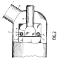
- FIGs. 1 and 2 are shown schematically part of a heat exchanger which consists of a plate bundle 1 arranged inside a calender 2.
- the plate bundle 1 is formed of a multitude of plates 10, arranged contiguously and parallel to each other.
- the plates 10 made of thin sheets, most often made of stainless steel, have edges with a smooth surface and a central part provided with corrugations by which they are in contact with one another and by which they delimit a double circulation circuit independent and counter-current fluids from one end to the other of the exchanger.
- the plate bundle comprises, at its lower end, a manifold 11 for the outlet of a heat transfer fluid, connected, on the one hand, to one of the circuits of said plate bundle 1, and on the other hand, to a pipe 12 evacuation of said fluid.
- This heat transfer fluid is introduced into the corresponding circuit of the plate bundle 1 through the upper end of said plate bundle.
- the fluid to be heated which in this case consists of a mixture of liquid and gas, is introduced through the lower end of the plate bundle 1.
- This fluid to be heated circulates in the other circuit of the plate bundle 1 and against the current of the fluid to be cooled.
- the calender 2 is connected to a pipe 14 for introducing the gas into the corresponding circuit of the plate bundle 1.
- the heat exchanger includes a device 20 for injecting the liquid into this circuit.
- Line 14 brings the gas inside the enclosure and into the beam charge circuit at plates 1.
- the liquid injection device 20 comprises, in the embodiment shown in Figs. 1 and 2, parallel pipes 21 arranged on either side of the manifold 11.
- the tubing 21 has its axis perpendicular to the channels of the corresponding circuit of the plate bundle 1 and extends over the entire width of said plate bundle 1.
- the tubing 21 has a first open end 21a connected to means for supplying the pressurized liquid, not shown, and a second closed end 22b.
- This tubing 21 has calibrated orifices 22 for spraying the pressurized liquid into the channels of the corresponding circuit of the plate bundle 1, distributed along generators and over the entire length of said tubing.
- the pressurized liquid enters the tubing 21 through its end 21a, and is sprayed upwards through all of the calibrated orifices 22.
- This pressurized liquid is then taken up by the gas which circulates at high speed at the entrance to the plate bundle 1, mixes intimately with it, and circulates in the channels of the corresponding circuit of the plate bundle 1, intimately mixed with the gas.
- the double mixed phase thus created is advantageously distributed over the entire width of these channels and is then entrained by the gas to the top of the plate beam 1.
- the tube 21 comprises means for maintaining the liquid at a non-zero speed over its entire length and means for emptying said tube 21.
- This accumulation is due to the speed profile, which is zero at the bottom of the pipe 21.
- the particles entering it are carried at high speed towards the bottom, practically in a straight line, where they crash, lose their speed, and fall to the bottom of the tubing where they accumulate.
- the fine particles are constantly entrained and follow the fluid threads until their discharge through the calibrated orifices 22.
- these means for maintaining a constant speed of the liquid are formed by all or part of the tube 21 of progressively decreasing section relative to the direction of circulation of the liquid in said tube 21.
- the part of the tubing 21 of progressively decreasing section is formed, for example, by a ramped portion 23 disposed opposite the calibrated orifices 22 and near the closed end 21b of the tubing 21.
- the tubing 21 has a length of between 1 and 1.3 m, a diameter of between between 5 and 15 cm and the ramp portion 23 represents approximately 20 to 50% of the length of the tubing 21.
- the ramp portion 23 can extend over the entire length of the tube 21.
- the fine particles are constantly entrained at non-zero speed and follow the fluid threads until they are discharged through the calibrated orifices 22.
- the liquid is no longer filtered, and certain filter debris ends up in the pipe 21.
- This debris with a diameter greater than the diameter of the calibrated orifices 22 accumulates at the bottom of the tube 21 and obtains the calibrated orifices 22.
- the end 21b of the tubing 21 is equipped with means for emptying said tubing 21 which are constituted by a sealed isolation valve 24.
- the end 21b of the tubing 21 is connected to the sealed isolation valve 24 situated outside the calender 2 by a conduit 25.
- the conduit 25 is connected, on the one hand, to the end 21b of the pipe 21 by a flange 26 and a bayonet system 27 and, on the other hand, to the isolation valve 24 by a flange 28.
- the conduit 25 can be produced, either at using a hose, or using a rigid pipe fitted with two expansion joints 29.
- the downstream side of the isolation valve 24 is connected to a discharge circuit, not shown.
- the isolation valve 24 is then quickly opened for a very short time and under the effect of the pressure, the debris plug is immediately removed.
- the isolation valve 24 is immediately closed, as soon as the pressure drop in the pipe 21 returns to its normal value.
- the injection device according to the invention makes it possible to avoid an accumulation of debris inside the tubing, while retaining its efficiency.
Abstract
Description
La présente invention a pour objet un dispositif d'injection d'un fluide sous pression dans un faisceau à plaques d'un échangeur thermique.The present invention relates to a device for injecting a pressurized fluid into a plate bundle of a heat exchanger.
Les échangeurs thermiques sont généralement de deux types.There are generally two types of heat exchangers.
Le premier type d'échangeur thermique comporte un faisceau de tubes en forme de "U" ou un faisceau de tubes droits, dans lequel circule un fluide.The first type of heat exchanger comprises a bundle of tubes in the shape of a "U" or a bundle of straight tubes, in which a fluid circulates.
Mais ce type d'échangeurs est d'une conception coûteuse et le rendement thermique est limité compte tenu que le nombre de tubes dépend de la place disponible qui est dans la plupart des cas restreinte.However, this type of exchanger is of an expensive design and the thermal efficiency is limited, given that the number of tubes depends on the space available which is in most cases limited.
Le second type d'échangeur thermique, comporte un faisceau de plaques disposées jointivement et parallèlement les unes aux autres.The second type of heat exchanger comprises a bundle of plates arranged contiguously and parallel to each other.
Les plaques constituées de tôles fines, le plus souvent en acier inoxydable, comportent des bords à surface lisse et une partie centrale munie d'ondulations par lesquelles elles sont en contact les unes sur les autres et par lesquelles elles délimitent des canaux formant un double circuit de circulation de fluides indépendants et à contre-courant d'une extrémité à l'autre de l'échangeur thermique.The plates made of thin sheets, most often made of stainless steel, have edges with a smooth surface and a central part provided with corrugations by which they are in contact with each other and by which they delimit channels forming a double circuit. circulation of independent fluids and against the current from one end to the other of the heat exchanger.
Ce type d'échangeurs thermiques à faisceau de plaques fonctionne avec divers fluides, en simple phase ou en double phase.This type of plate bundle heat exchangers works with various fluids, in single phase or in double phase.
Dans le cas où la charge à réchauffer est introduite dans l'échangeur sous double phase, il convient d'assurer un mélange intime du liquide et du gaz afin d'assurer une distribution régulière du mélange dans la totalité du faisceau de plaques de l'échangeur thermique.In the case where the charge to be heated is introduced into the dual phase exchanger, it is necessary to ensure an intimate mixture of the liquid and the gas in order to ensure a regular distribution of the mixture throughout the entire bundle of plates of the heat exchanger.
Pour assurer le mélange intime du liquide et du gaz, on utilise un dispositif d'injection de la phase liquide seule.To ensure the intimate mixing of the liquid and gas, a device for injecting the liquid phase alone is used.
Ce dispositif d'injection consiste en une ou plusieurs tubulures s'étendant sur toute la largeur du faisceau à plaques et munies d'une première extrémité ouverte reliée à des moyens d'alimentation du fluide sous pression et d'une seconde extrémité fermée.This injection device consists of one or more pipes extending over the entire width of the plate bundle and provided with a first open end connected to means for supplying the fluid under pressure and with a second closed end.
La tubulure est généralement placée à la partie inférieure du faisceau à plaques et son axe est perpendiculaire aux canaux dudit faisceau à plaques.The tubing is generally placed at the bottom of the plate bundle and its axis is perpendicular to the channels of said plate bundle.
Par ailleurs, la tubulure comporte des orifices calibrés de pulvérisation du liquide dans les canaux du faisceau à plaques, le long de génératrices et sur toute la longueur de ladite tubulure.Furthermore, the tubing has calibrated orifices for spraying the liquid into the channels of the plate bundle, along generators and over the entire length of said tubing.
Le liquide sous pression entre dans la tubulure à une extrémité, et est pulvérisé vers le haut à travers l'ensemble des canaux du faisceau à plaques.The pressurized liquid enters the tubing at one end, and is sprayed upward through all of the plate bundle channels.
Ce liquide sous pression est alors pris en charge par le gaz qui circule à grande vitesse à l'entrée du fasiceau, se mélange intimement à lui, et circule dans le faisceau à plaques mélangé audit gaz.This pressurized liquid is then taken up by the gas which circulates at high speed at the inlet of the fascia, mixes intimately with it, and circulates in the plate bundle mixed with said gas.
La double phase mixte ainsi créée se distribue avantageusement dans toute la largeur des canaux et est ensuite entraînée par le gaz jusqu'au sommet du faisceau à plaques.The double mixed phase thus created is advantageously distributed over the entire width of the channels and is then entrained by the gas to the top of the plate beam.
Ce type de dispositif d'injection utilisé jusqu'à présent remplit parfaitement la fonction principale pour laquelle il a été conçu, à savoir assurer un mélange intime entre le liquide et le gaz et par conséquence, créer les conditions d'une distribution homogène et régulière de la double phase dès son entrée dans le faisceau à plaques.This type of injection device used until now perfectly fulfills the main function for which it was designed, namely to ensure an intimate mixture between the liquid and the gas and consequently create the conditions for a homogeneous and regular distribution. of the double phase as soon as it enters the plate beam.
Par contre, un inconvénient majeur se produit parfois, soit dès la mise en service, soit accidentellement en marche permanente.On the other hand, a major drawback sometimes occurs, either from commissioning, or accidentally in permanent operation.
En effet, les orifices calibrés, de petits diamètres, se bouchent partiellement ou totalement et ce malgré la présence de filtres à mailles fines à l'entrée de la tubulure et l'installation doit être périodiquement arrêtée pour retirer les tubulures et les nettoyer.Indeed, the calibrated orifices, of small diameters, become partially or totally blocked, despite the presence of fine mesh filters at the inlet of the tubing and the installation must be periodically stopped to remove the tubing and clean it.
Le bouchage des orifices calibrés de la tubulure est provoqué par de fines particules, par exemple des oxydes de fer ou autres, qui proviennent d'une accumulation et d'une stagnation de ces particules au fond de la tubulure, à l'extrémité opposée de l'entrée.Clogging of the calibrated orifices of the tubing is caused by fine particles, for example iron oxides or others, which come from an accumulation and stagnation of these particles at the bottom of the tubing, at the opposite end of the entrance.
En effet, les particules qui pénètrent dans la tubulure sont entraînées à grande vitesse vers le fond de cette tubulure, pratiquement en ligne droite, où elles s'écrasent, perdent leur vitesse, et tombent à la partie inférieure de la tubulure où elles s'accumulent.Indeed, the particles which penetrate into the tubing are entrained at high speed towards the bottom of this tubing, practically in a straight line, where they crush, lose their speed, and fall to the lower part of the tubing where they accumulate.
Ainsi, il se forme un bouchon de particules qui part lentement du fond de la tubulure et gagne peu à peu l'avant de cette tubulure cachant de plus en plus d'orifices calibrés, jusqu'à l'obturation totale.Thus, a particle plug is formed which leaves slowly from the bottom of the tubing and gradually gains the front of this tubing hiding more and more calibrated orifices, until total closure.
L'invention a pour but d'éviter cet inconvénient tout en conservant au dispositif d'injection son efficacité.The invention aims to avoid this drawback while retaining the efficiency of the injection device.
L'invention a donc pour objet un dispositif d'injection d'un fluide sous pression dans un faisceau à plaques d'un échangeur thermique comportant des canaux de circulation dudit fluide, ledit dispositif comprenant au moins une tubulure s'étendant sur toute la largeur du faisceau à plaques et munie d'une première extrémité ouverte reliée à des moyens d'alimentation du fluide sous pression et d'une seconde extrémité fermée, ladite tubulure comportant des orifices calibrés de pulvérisation dudit fluide dans les canaux du faisceau à plaques, répartis le long de génératrices et sur toute la longueur de la tubulure, caractérisé en ce que la tubulure comporte des moyens de maintien du fluide à une vitesse non nulle sur toute sa longueur et des moyens de vidange de ladite tubulure.The invention therefore relates to a device for injecting a pressurized fluid into a plate bundle of a heat exchanger comprising circulation channels of said fluid, said device comprising at least one tube extending over the entire width. of the plate bundle and provided with a first open end connected to means for supplying the pressurized fluid and with a second closed end, said tube having calibrated orifices for spraying said fluid into the channels of the plate bundle, distributed along generators and along the entire length of the tubing, characterized in that the tubing comprises means for maintaining the fluid at a non-zero speed over its entire length and means for emptying said tube.
Selon d'autres caractéristiques de l'invention :
- les moyens de maintien à une vitesse non nulle du fluide sont formés par tout ou partie de la tubulure de section progressivement décroissante par rapport au sens de circulation du fluide,
- la partie de la tubulure de section progressivement décroissante est formée par une portion en rampe disposée à l'opposé des orifices calibrés et à proximité de l'extrémité fermée de la tubulure,
- la portion en rampe représente environ 20 à 50% de la longueur de la tubulure,
- la portion en rampe s'étend sur toute la longueur de la tubulure,
- les moyens de vidange de la tubulure sont formés par une vanne d'isolement étanche disposée à l'extrémité de la tubulure opposée à l'extrémité ouverte.
- the means for maintaining the fluid at a non-zero speed are formed by all or part of the tube of progressively decreasing section relative to the direction of circulation of the fluid,
- the part of the tubing of progressively decreasing section is formed by a ramped portion disposed opposite the calibrated orifices and near the closed end of the tubing,
- the ramp portion represents approximately 20 to 50% of the length of the tubing,
- the ramp portion extends over the entire length of the tubing,
- the means for draining the tubing are formed by a sealed isolation valve disposed at the end of the tubing opposite the open end.
Les caractéristiques et avantages de l'invention apparaîtront au cours de la description qui va suivre, donnée uniquement à titre d'exemple et faite en référence aux dessins annexés, sur lesquels :
- la Fig. 1 est une vue schématique partielle et en perspective d'un échangeur thermique muni du dispositif d'injection d'un fluide sous pression selon l'invention,
- la Fig. 2 est une vue schématique partiellement en coupe selon la ligne 2-2 de la Fig. 1,
- la Fig. 3 est une vue schématique montrant un exemple de raccordement d'une tubulure du dispositif d'injection d'un fluide avec les moyens de vidange de cette tubulure.
- Fig. 1 is a partial schematic perspective view of a heat exchanger fitted with the device for injecting a pressurized fluid according to the invention,
- Fig. 2 is a schematic view partially in section on line 2-2 of FIG. 1,
- Fig. 3 is a schematic view showing an example of connection of a tubing of the fluid injection device with the means for emptying this tubing.
Sur les Figs. 1 et 2 on a représenté schématiquement une partie d'un échangeur thermique qui se compose d'un faisceau à plaques 1 disposé à l'intérieur d'une calandre 2.In Figs. 1 and 2 are shown schematically part of a heat exchanger which consists of a plate bundle 1 arranged inside a
De manière classique, le faisceau à plaques 1 est formé d'une multitude de plaques 10, disposées jointivement et parallèlement les unes aux autres.Conventionally, the plate bundle 1 is formed of a multitude of
Les plaques 10 constituées de tôles fines, le plus souvent en acier inoxydable, comportent des bords à surface lisse et une partie centrale munie d'ondulations par lesquelles elles sont en contact les unes sur les autres et par lesquelles elles délimitent un double circuit de circulation de fluides indépendants et à contre-courant d'une extrémité à l'autre de l'échangeur.The
Le faisceau à plaques comporte, à son extrémité inférieure, un collecteur 11 de sortie d'un fluide caloporteur, raccordé, d'une part, à l'un des circuits dudit faisceau à plaques 1, et d'autre part, à une conduite 12 d'évacuation dudit fluide.The plate bundle comprises, at its lower end, a
Ce fluide caloporteur est introduit dans le circuit correspondant du faisceau à plaques 1 par l'extrémité supérieure dudit faisceau à plaques.This heat transfer fluid is introduced into the corresponding circuit of the plate bundle 1 through the upper end of said plate bundle.
Le fluide à réchauffer qui dans le cas présent est constitué par un mélange de liquide et de gaz, est introduit par l'extrémité inférieure du faisceau à plaques 1.The fluid to be heated, which in this case consists of a mixture of liquid and gas, is introduced through the lower end of the plate bundle 1.
Ce fluide à réchauffer circule dans l'autre circuit du faisceau à plaques 1 et à contre-courant du fluide à refroidir.This fluid to be heated circulates in the other circuit of the plate bundle 1 and against the current of the fluid to be cooled.
A cet effet, la calendre 2 est raccordée à une conduite 14 d'introduction du gaz dans le circuit correspondant du faisceau à plaques 1. L'échangeur thermique comporte un dispositif 20 d'injection du liquide dans ce circuit.For this purpose, the
La conduite 14 amène le gaz à l'intérieur de l'enceinte et dans le circuit charge du faisceau à plaques 1.
Le dispositif d'injection 20 du liquide comporte, dans l'exemple de réalisation représenté sur les Figs. 1 et 2, des tubulures 21 parallèles et disposées de part et d'autre du collecteur 11.The
Dans ce qui suit, on ne décrira qu'une tubulure 21, l'autre tubulure étant identique.In what follows, only one
La tubulure 21 a son axe perpendiculaire aux canaux du circuit correspondant du faisceau à plaques 1 et s'étend sur toute la largeur dudit faisceau à plaques 1.The
La tubulure 21 comporte une première extrémité ouverte 21a reliée à des moyens d'alimentation du liquide sous pression, non représentés, et une seconde extrémité fermée 22b.The
Cette tubulure 21 comporte des orifices calibrés 22 de pulvérisation du liquide sous pression dans les canaux du circuit correspondant du faisceau à plaques 1, répartis le long de génératrices et sur toute la longueur de ladite tubulure.This
Le liquide sous pression entre dans la tubulure 21 par son extrémité 21a, et est pulvérisé vers le haut à travers l'ensemble des orifices calibrés 22.The pressurized liquid enters the
Ce liquide sous pression est alors pris en charge par le gaz qui circule à grande vitesse à l'entrée du faisceau à plaques 1, se mélange intimement à lui, et circule dans les canaux du circuit correspondant du faisceau à plaques 1, mélangé intimement au gaz.This pressurized liquid is then taken up by the gas which circulates at high speed at the entrance to the plate bundle 1, mixes intimately with it, and circulates in the channels of the corresponding circuit of the plate bundle 1, intimately mixed with the gas.
La double phase mixte ainsi créée se distribue avantageusement sur toute la largeur de ces canaux et est ensuite entraînée par le gaz jusqu'au sommet du faisceau à plaques 1.The double mixed phase thus created is advantageously distributed over the entire width of these channels and is then entrained by the gas to the top of the plate beam 1.
La tubulure 21 comporte des moyens de maintien du liquide à une vitesse non nulle sur toute sa longueur et des moyens de vidange de ladite tubulure 21.The
En effet, une analyse en laboratoire du phénomène de bouchage des orifices calibrés 22 des tubulures 21 a montré que ce bouchage par de fines particules, souvent des oxydes de fer ou autres, provient d'une accumulation et d'une stagnation desdites particules au fond de la tubulure 21 à l'opposé de l'extrémité ouverte 21a.In fact, a laboratory analysis of the plugging phenomenon of the
Cette accumulation est due au profil des vitesses, qui est nul au fond de la tubulure 21.This accumulation is due to the speed profile, which is zero at the bottom of the
Les particules qui y pénètrent sont entraînées à grande vitesse vers le fond, pratiquement en ligne droite, où elles s'écrasent, perdent leur vitesse, et tombent à la partie inférieure de la tubulure où elles s'accumulent.The particles entering it are carried at high speed towards the bottom, practically in a straight line, where they crash, lose their speed, and fall to the bottom of the tubing where they accumulate.
Il se forme ainsi un bouchon de débris qui part lentement du fond de la tubulure 21 et gagne peu à peur vers l'avant, cachant de plus en plus d'orifices calibrés 22 jusqu'à l'obturation généralisée.There is thus formed a plug of debris which leaves slowly from the bottom of the
Grâce aux moyens de maintien du liquide à une vitesse non nulle sur toute la longueur de la tubulure 21, les fines particules sont constamment entraînées et suivent les filets fluides jusqu'à leur évacuation à travers les orifices calibrés 22.Thanks to the means for holding the liquid at a non-zero speed over the entire length of the
Comme représenté sur les Figs. 1 et 3, ces moyens de maintien à une vitesse constante du liquide sont formés par tout ou partie de la tubulure 21 de section progressivement décroissante par rapport au sens de circulation du liquide dans ladite tubulure 21.As shown in Figs. 1 and 3, these means for maintaining a constant speed of the liquid are formed by all or part of the
La partie de la tubulure 21 de section progressivement décroissante est formée, par exemple, par une portion en rampe 23 disposée à l'opposé des orifices calibrés 22 et à proximité de l'extrémité fermée 21b de la tubulure 21.The part of the
A titre d'exemple, la tubulure 21 a une longueur comprise entre 1 et 1,3 m, un diamètre compris entre 5 et 15 cm et la portion en rampe 23 représente environ 20 à 50% de la longueur de la tubulure 21.By way of example, the
Selon une variante, la portion en rampe 23 peut s'étendre sur toute la longueur de la tubulure 21.According to a variant, the
Grâce à la portion en rampe 23, les fines particules sont constamment entraînées à vitesse non nulle et suivent les filets fluides jusqu'à leur évacuation à travers les orifices calibrés 22.Thanks to the
Il ne se produit donc plus d'accumulation de fines particules dans la tubulure 21, spécialement à l'extrémité 21b opposée à l'entrée 21a du liquide dans ladite tubulure 21.There is therefore no longer any accumulation of fine particles in the
Mais, il peut arriver que les filtres placés en amont de la tubulure 21 soient partiellement détruits.However, it may happen that the filters placed upstream of the
Dans ce cas, le liquide n'est plus filtré, et certains débris de filtre se retrouvent dans la tubulure 21.In this case, the liquid is no longer filtered, and certain filter debris ends up in the
Ces débris de diamètre supérieur au diamètre des orifices calibrés 22 s'accumulent au fond de la tubulure 21 et obturent les orifices calibrés 22.This debris with a diameter greater than the diameter of the calibrated
Il convient donc de pouvoir les évacuer au cours du fonctionnement de l'échangeur thermique.It is therefore advisable to be able to evacuate them during the operation of the heat exchanger.
A cet effet, l'extrémité 21b de la tubulure 21 est équipée de moyens de vidange de ladite tubulure 21 qui sont constitués par une vanne d'isolement étanche 24.To this end, the
Comme représenté à la Fig. 3, l'extrémité 21b de la tubulure 21 est raccordée à la vanne d'isolement étanche 24 située à l'extérieur de la calandre 2 par un conduit 25.As shown in Fig. 3, the
Le conduit 25 est relié, d'une part, à l'extrémité 21b de la tubulure 21 par une bride 26 et un système à baïonnette 27 et, d'autre part, à la vanne d'isolement 24 par une bride 28.The
Le conduit 25 peut être réalisé, soit à l'aide d'un flexible, soit à l'aide d'une conduite rigide munie de deux compensateurs de dilatation 29.The
L'aval de la vanne d'isolement 24 est connecté à un circuit de décharge, non représenté.The downstream side of the
En cas d'obturation de la tubulure 21 par de gros débris, on constate une augmentation de la perte de charge à travers la tubulure 21.If the
Dans ce cas, on ouvre alors rapidement la vanne d'isolement 24 pendant un temps très court et sous l'effet de la pression, le bouchon de débris est aussitôt évacué.In this case, the
Ensuite, la vanne d'isolement 24 est immédiatement refermée, dès que la perte de charge dans la tubulure 21 revient à sa valeur normale.Then, the
Le dispositif d'injection selon l'invention permet d'éviter une accumulation de débris à l'intérieur de la tubulure, tout en conservant à cette tubulure son efficacité.The injection device according to the invention makes it possible to avoid an accumulation of debris inside the tubing, while retaining its efficiency.
Claims (6)
Applications Claiming Priority (2)
| Application Number | Priority Date | Filing Date | Title |
|---|---|---|---|
| FR9402548 | 1994-03-04 | ||
| FR9402548A FR2716961B1 (en) | 1994-03-04 | 1994-03-04 | Device for injecting a pressurized fluid into a plate bundle of a heat exchanger. |
Publications (1)
| Publication Number | Publication Date |
|---|---|
| EP0670464A1 true EP0670464A1 (en) | 1995-09-06 |
Family
ID=9460711
Family Applications (1)
| Application Number | Title | Priority Date | Filing Date |
|---|---|---|---|
| EP95400270A Withdrawn EP0670464A1 (en) | 1994-03-04 | 1995-02-09 | Apparatus for injecting a pressure fluid in a stack of plates of a heat exchanger |
Country Status (2)
| Country | Link |
|---|---|
| EP (1) | EP0670464A1 (en) |
| FR (1) | FR2716961B1 (en) |
Cited By (1)
| Publication number | Priority date | Publication date | Assignee | Title |
|---|---|---|---|---|
| FR2763118A1 (en) * | 1997-05-09 | 1998-11-13 | Packinox Sa | DEVICE FOR INJECTING PRESSURE FLUIDS INTO A PLATE HEAT EXCHANGER AND METHOD FOR CLEANING SUCH AN INJECTION DEVICE |
Citations (5)
| Publication number | Priority date | Publication date | Assignee | Title |
|---|---|---|---|---|
| GB413947A (en) * | 1933-12-06 | 1934-07-26 | Robert Morton & Company Ltd | Improvements in or relating to wort coolers and similar heat exchange apparatus |
| US3128046A (en) * | 1960-09-23 | 1964-04-07 | A E Broughton & Co Inc | Non-clogging spray nozzle |
| FR1396037A (en) * | 1963-04-29 | 1965-04-16 | Cie Europ Des Materiels Thermi | heat exchanger |
| EP0106544A1 (en) * | 1982-09-16 | 1984-04-25 | Kabushiki Kaisha Kobe Seiko Sho | Distributor apparatus for fluid including a gaseous and liquid phase |
| DE3310236A1 (en) * | 1983-03-22 | 1984-09-27 | Autokühler-Gesellschaft mbH, 3520 Hofgeismar | Refrigerant distributor for the evaporator of a refrigerator or heat pump |
-
1994
- 1994-03-04 FR FR9402548A patent/FR2716961B1/en not_active Expired - Fee Related
-
1995
- 1995-02-09 EP EP95400270A patent/EP0670464A1/en not_active Withdrawn
Patent Citations (5)
| Publication number | Priority date | Publication date | Assignee | Title |
|---|---|---|---|---|
| GB413947A (en) * | 1933-12-06 | 1934-07-26 | Robert Morton & Company Ltd | Improvements in or relating to wort coolers and similar heat exchange apparatus |
| US3128046A (en) * | 1960-09-23 | 1964-04-07 | A E Broughton & Co Inc | Non-clogging spray nozzle |
| FR1396037A (en) * | 1963-04-29 | 1965-04-16 | Cie Europ Des Materiels Thermi | heat exchanger |
| EP0106544A1 (en) * | 1982-09-16 | 1984-04-25 | Kabushiki Kaisha Kobe Seiko Sho | Distributor apparatus for fluid including a gaseous and liquid phase |
| DE3310236A1 (en) * | 1983-03-22 | 1984-09-27 | Autokühler-Gesellschaft mbH, 3520 Hofgeismar | Refrigerant distributor for the evaporator of a refrigerator or heat pump |
Cited By (3)
| Publication number | Priority date | Publication date | Assignee | Title |
|---|---|---|---|---|
| FR2763118A1 (en) * | 1997-05-09 | 1998-11-13 | Packinox Sa | DEVICE FOR INJECTING PRESSURE FLUIDS INTO A PLATE HEAT EXCHANGER AND METHOD FOR CLEANING SUCH AN INJECTION DEVICE |
| EP0877222A3 (en) * | 1997-05-09 | 2000-02-23 | Packinox | Device for injecting pressurized fluids in a plate-like heat exchanger and process for cleaning this injection device |
| US6196301B1 (en) | 1997-05-09 | 2001-03-06 | Packinox | Device for injecting pressurized fluids into a multiplate heat exchanger and method of cleaning such an injection device |
Also Published As
| Publication number | Publication date |
|---|---|
| FR2716961A1 (en) | 1995-09-08 |
| FR2716961B1 (en) | 1996-06-14 |
Similar Documents
| Publication | Publication Date | Title |
|---|---|---|
| EP1800725B1 (en) | Chamber for hydrocarbons treatment containing an element for draining | |
| WO2007054360A1 (en) | Liquid filtration system | |
| EP0219882B1 (en) | Process and automatic cleaning device for gaseous fluids | |
| EP2875304A1 (en) | Plate exchanger absorber with porous distribution element | |
| EP0877222B1 (en) | Device for injecting pressurized fluids in a plate-like heat exchanger and process for cleaning this injection device | |
| EP0068958B1 (en) | Steam generator with a dynamic discharge system | |
| EP0670464A1 (en) | Apparatus for injecting a pressure fluid in a stack of plates of a heat exchanger | |
| EP2239064A1 (en) | Ball cleaning system, particularly for a plate heat exchanger | |
| FR3068030A1 (en) | FERROUS PARTICLE CAPTURING DEVICE COMPRISING AN ENCLOSURE IN WHICH AT LEAST ONE REMOVABLE MAGNET BAR IS PRESENT | |
| KR101936714B1 (en) | Pipe cleaning system | |
| FR2793427A1 (en) | Device for picking up metal particles suspended in fluid in closed circuit heating system comprises tank fitted with fluid inlet and outlet, glove finger and magnetic bar | |
| EP1143153B1 (en) | Tee with a device for diminishing vibrations and shocks in a gaseous fluid network, conduit network equipped with such a tee | |
| FR2957999A1 (en) | PISTON WITH JOINT CONDUIT | |
| EP1797963A1 (en) | Mixing chamber and spraying device comprising said chamber | |
| FR2515558A1 (en) | APPARATUS AND METHOD FOR DISPENSING AN ABRASIVE IN A GAS STREAM | |
| FR2704769A1 (en) | Filtration device for clearing mud from pipework systems in which a fluid laden with impurities circulates | |
| FR2746666A1 (en) | Apparatus for removing dust from air | |
| BE1012278A3 (en) | Boiler manifold and boiler fitted with such a manifold | |
| FR2700605A1 (en) | Sludge or sediment injection into waste incinerator | |
| EP1704379A1 (en) | Heat exchanger comprising cleaning means | |
| JPS6159116A (en) | Method of purging and cleaning tube for coal/water slurry and device thereof | |
| WO2011144862A2 (en) | Method and device for heat exchanger fouling removal | |
| WO2011141670A1 (en) | Method and device for unclogging a heat exchanger | |
| FR2508156A1 (en) | Protecting the inlet ends of heat exchanger tubes from erosion - by providing each tube with extension tube made of hardened carbon steel (ZA 11.10.82) | |
| EP3623063A1 (en) | Device for maintenance of a particle filter of an exhaust device intended for equipping a combustion engine |
Legal Events
| Date | Code | Title | Description |
|---|---|---|---|
| PUAI | Public reference made under article 153(3) epc to a published international application that has entered the european phase |
Free format text: ORIGINAL CODE: 0009012 |
|
| AK | Designated contracting states |
Kind code of ref document: A1 Designated state(s): AT BE CH DE DK ES GB GR IE IT LI NL PT SE |
|
| 17P | Request for examination filed |
Effective date: 19960206 |
|
| 17Q | First examination report despatched |
Effective date: 19970408 |
|
| STAA | Information on the status of an ep patent application or granted ep patent |
Free format text: STATUS: THE APPLICATION IS DEEMED TO BE WITHDRAWN |
|
| 18D | Application deemed to be withdrawn |
Effective date: 19971021 |