EP0670464A1 - Vorrichtung zum Druckspritzen eines Fluidums in einem Plattenstapel eines Wärmetauschers - Google Patents
Vorrichtung zum Druckspritzen eines Fluidums in einem Plattenstapel eines Wärmetauschers Download PDFInfo
- Publication number
- EP0670464A1 EP0670464A1 EP95400270A EP95400270A EP0670464A1 EP 0670464 A1 EP0670464 A1 EP 0670464A1 EP 95400270 A EP95400270 A EP 95400270A EP 95400270 A EP95400270 A EP 95400270A EP 0670464 A1 EP0670464 A1 EP 0670464A1
- Authority
- EP
- European Patent Office
- Prior art keywords
- tubing
- tube
- fluid
- plate bundle
- heat exchanger
- Prior art date
- Legal status (The legal status is an assumption and is not a legal conclusion. Google has not performed a legal analysis and makes no representation as to the accuracy of the status listed.)
- Withdrawn
Links
Images


Classifications
-
- F—MECHANICAL ENGINEERING; LIGHTING; HEATING; WEAPONS; BLASTING
- F28—HEAT EXCHANGE IN GENERAL
- F28F—DETAILS OF HEAT-EXCHANGE AND HEAT-TRANSFER APPARATUS, OF GENERAL APPLICATION
- F28F9/00—Casings; Header boxes; Auxiliary supports for elements; Auxiliary members within casings
- F28F9/02—Header boxes; End plates
- F28F9/026—Header boxes; End plates with static flow control means, e.g. with means for uniformly distributing heat exchange media into conduits
- F28F9/027—Header boxes; End plates with static flow control means, e.g. with means for uniformly distributing heat exchange media into conduits in the form of distribution pipes
- F28F9/0273—Header boxes; End plates with static flow control means, e.g. with means for uniformly distributing heat exchange media into conduits in the form of distribution pipes with multiple holes
-
- F—MECHANICAL ENGINEERING; LIGHTING; HEATING; WEAPONS; BLASTING
- F28—HEAT EXCHANGE IN GENERAL
- F28D—HEAT-EXCHANGE APPARATUS, NOT PROVIDED FOR IN ANOTHER SUBCLASS, IN WHICH THE HEAT-EXCHANGE MEDIA DO NOT COME INTO DIRECT CONTACT
- F28D9/00—Heat-exchange apparatus having stationary plate-like or laminated conduit assemblies for both heat-exchange media, the media being in contact with different sides of a conduit wall
Definitions
- the present invention relates to a device for injecting a pressurized fluid into a plate bundle of a heat exchanger.
- the first type of heat exchanger comprises a bundle of tubes in the shape of a "U" or a bundle of straight tubes, in which a fluid circulates.
- the second type of heat exchanger comprises a bundle of plates arranged contiguously and parallel to each other.
- the plates made of thin sheets most often made of stainless steel, have edges with a smooth surface and a central part provided with corrugations by which they are in contact with each other and by which they delimit channels forming a double circuit. circulation of independent fluids and against the current from one end to the other of the heat exchanger.
- a device for injecting the liquid phase alone is used.
- This injection device consists of one or more pipes extending over the entire width of the plate bundle and provided with a first open end connected to means for supplying the fluid under pressure and with a second closed end.
- the tubing is generally placed at the bottom of the plate bundle and its axis is perpendicular to the channels of said plate bundle.
- the tubing has calibrated orifices for spraying the liquid into the channels of the plate bundle, along generators and over the entire length of said tubing.
- the pressurized liquid enters the tubing at one end, and is sprayed upward through all of the plate bundle channels.
- This pressurized liquid is then taken up by the gas which circulates at high speed at the inlet of the fascia, mixes intimately with it, and circulates in the plate bundle mixed with said gas.
- the double mixed phase thus created is advantageously distributed over the entire width of the channels and is then entrained by the gas to the top of the plate beam.
- the calibrated orifices of small diameters, become partially or totally blocked, despite the presence of fine mesh filters at the inlet of the tubing and the installation must be periodically stopped to remove the tubing and clean it.
- Clogging of the calibrated orifices of the tubing is caused by fine particles, for example iron oxides or others, which come from an accumulation and stagnation of these particles at the bottom of the tubing, at the opposite end of the entrance.
- the particles which penetrate into the tubing are entrained at high speed towards the bottom of this tubing, practically in a straight line, where they crush, lose their speed, and fall to the lower part of the tubing where they accumulate.
- a particle plug is formed which leaves slowly from the bottom of the tubing and gradually gains the front of this tubing hiding more and more calibrated orifices, until total closure.
- the invention aims to avoid this drawback while retaining the efficiency of the injection device.
- the invention therefore relates to a device for injecting a pressurized fluid into a plate bundle of a heat exchanger comprising circulation channels of said fluid, said device comprising at least one tube extending over the entire width. of the plate bundle and provided with a first open end connected to means for supplying the pressurized fluid and with a second closed end, said tube having calibrated orifices for spraying said fluid into the channels of the plate bundle, distributed along generators and along the entire length of the tubing, characterized in that the tubing comprises means for maintaining the fluid at a non-zero speed over its entire length and means for emptying said tube.
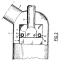
- FIGs. 1 and 2 are shown schematically part of a heat exchanger which consists of a plate bundle 1 arranged inside a calender 2.
- the plate bundle 1 is formed of a multitude of plates 10, arranged contiguously and parallel to each other.
- the plates 10 made of thin sheets, most often made of stainless steel, have edges with a smooth surface and a central part provided with corrugations by which they are in contact with one another and by which they delimit a double circulation circuit independent and counter-current fluids from one end to the other of the exchanger.
- the plate bundle comprises, at its lower end, a manifold 11 for the outlet of a heat transfer fluid, connected, on the one hand, to one of the circuits of said plate bundle 1, and on the other hand, to a pipe 12 evacuation of said fluid.
- This heat transfer fluid is introduced into the corresponding circuit of the plate bundle 1 through the upper end of said plate bundle.
- the fluid to be heated which in this case consists of a mixture of liquid and gas, is introduced through the lower end of the plate bundle 1.
- This fluid to be heated circulates in the other circuit of the plate bundle 1 and against the current of the fluid to be cooled.
- the calender 2 is connected to a pipe 14 for introducing the gas into the corresponding circuit of the plate bundle 1.
- the heat exchanger includes a device 20 for injecting the liquid into this circuit.
- Line 14 brings the gas inside the enclosure and into the beam charge circuit at plates 1.
- the liquid injection device 20 comprises, in the embodiment shown in Figs. 1 and 2, parallel pipes 21 arranged on either side of the manifold 11.
- the tubing 21 has its axis perpendicular to the channels of the corresponding circuit of the plate bundle 1 and extends over the entire width of said plate bundle 1.
- the tubing 21 has a first open end 21a connected to means for supplying the pressurized liquid, not shown, and a second closed end 22b.
- This tubing 21 has calibrated orifices 22 for spraying the pressurized liquid into the channels of the corresponding circuit of the plate bundle 1, distributed along generators and over the entire length of said tubing.
- the pressurized liquid enters the tubing 21 through its end 21a, and is sprayed upwards through all of the calibrated orifices 22.
- This pressurized liquid is then taken up by the gas which circulates at high speed at the entrance to the plate bundle 1, mixes intimately with it, and circulates in the channels of the corresponding circuit of the plate bundle 1, intimately mixed with the gas.
- the double mixed phase thus created is advantageously distributed over the entire width of these channels and is then entrained by the gas to the top of the plate beam 1.
- the tube 21 comprises means for maintaining the liquid at a non-zero speed over its entire length and means for emptying said tube 21.
- This accumulation is due to the speed profile, which is zero at the bottom of the pipe 21.
- the particles entering it are carried at high speed towards the bottom, practically in a straight line, where they crash, lose their speed, and fall to the bottom of the tubing where they accumulate.
- the fine particles are constantly entrained and follow the fluid threads until their discharge through the calibrated orifices 22.
- these means for maintaining a constant speed of the liquid are formed by all or part of the tube 21 of progressively decreasing section relative to the direction of circulation of the liquid in said tube 21.
- the part of the tubing 21 of progressively decreasing section is formed, for example, by a ramped portion 23 disposed opposite the calibrated orifices 22 and near the closed end 21b of the tubing 21.
- the tubing 21 has a length of between 1 and 1.3 m, a diameter of between between 5 and 15 cm and the ramp portion 23 represents approximately 20 to 50% of the length of the tubing 21.
- the ramp portion 23 can extend over the entire length of the tube 21.
- the fine particles are constantly entrained at non-zero speed and follow the fluid threads until they are discharged through the calibrated orifices 22.
- the liquid is no longer filtered, and certain filter debris ends up in the pipe 21.
- This debris with a diameter greater than the diameter of the calibrated orifices 22 accumulates at the bottom of the tube 21 and obtains the calibrated orifices 22.
- the end 21b of the tubing 21 is equipped with means for emptying said tubing 21 which are constituted by a sealed isolation valve 24.
- the end 21b of the tubing 21 is connected to the sealed isolation valve 24 situated outside the calender 2 by a conduit 25.
- the conduit 25 is connected, on the one hand, to the end 21b of the pipe 21 by a flange 26 and a bayonet system 27 and, on the other hand, to the isolation valve 24 by a flange 28.
- the conduit 25 can be produced, either at using a hose, or using a rigid pipe fitted with two expansion joints 29.
- the downstream side of the isolation valve 24 is connected to a discharge circuit, not shown.
- the isolation valve 24 is then quickly opened for a very short time and under the effect of the pressure, the debris plug is immediately removed.
- the isolation valve 24 is immediately closed, as soon as the pressure drop in the pipe 21 returns to its normal value.
- the injection device according to the invention makes it possible to avoid an accumulation of debris inside the tubing, while retaining its efficiency.
Landscapes
- Engineering & Computer Science (AREA)
- Physics & Mathematics (AREA)
- Thermal Sciences (AREA)
- Mechanical Engineering (AREA)
- General Engineering & Computer Science (AREA)
- Heat-Exchange Devices With Radiators And Conduit Assemblies (AREA)
Applications Claiming Priority (2)
| Application Number | Priority Date | Filing Date | Title |
|---|---|---|---|
| FR9402548 | 1994-03-04 | ||
| FR9402548A FR2716961B1 (fr) | 1994-03-04 | 1994-03-04 | Dispositif d'injection d'un fluide sous pression dans un faisceau à plaques d'un échangeur thermique. |
Publications (1)
| Publication Number | Publication Date |
|---|---|
| EP0670464A1 true EP0670464A1 (de) | 1995-09-06 |
Family
ID=9460711
Family Applications (1)
| Application Number | Title | Priority Date | Filing Date |
|---|---|---|---|
| EP95400270A Withdrawn EP0670464A1 (de) | 1994-03-04 | 1995-02-09 | Vorrichtung zum Druckspritzen eines Fluidums in einem Plattenstapel eines Wärmetauschers |
Country Status (2)
| Country | Link |
|---|---|
| EP (1) | EP0670464A1 (de) |
| FR (1) | FR2716961B1 (de) |
Cited By (1)
| Publication number | Priority date | Publication date | Assignee | Title |
|---|---|---|---|---|
| FR2763118A1 (fr) * | 1997-05-09 | 1998-11-13 | Packinox Sa | Dispositif d'injection de fluides sous pression dans un echangeur thermique a plaques et procede de nettoyage d'un tel dispositif d'injection |
Citations (5)
| Publication number | Priority date | Publication date | Assignee | Title |
|---|---|---|---|---|
| GB413947A (en) * | 1933-12-06 | 1934-07-26 | Robert Morton & Company Ltd | Improvements in or relating to wort coolers and similar heat exchange apparatus |
| US3128046A (en) * | 1960-09-23 | 1964-04-07 | A E Broughton & Co Inc | Non-clogging spray nozzle |
| FR1396037A (fr) * | 1963-04-29 | 1965-04-16 | Cie Europ Des Materiels Thermi | échangeur de chaleur |
| EP0106544A1 (de) * | 1982-09-16 | 1984-04-25 | Kabushiki Kaisha Kobe Seiko Sho | Vorrichtung zur Verteilung von Medien, in der gasförmigen und flüssigen Phase |
| DE3310236A1 (de) * | 1983-03-22 | 1984-09-27 | Autokühler-Gesellschaft mbH, 3520 Hofgeismar | Kaeltemittel-verteiler fuer den verdampfer einer kaeltemaschine oder einer waermepumpe |
-
1994
- 1994-03-04 FR FR9402548A patent/FR2716961B1/fr not_active Expired - Fee Related
-
1995
- 1995-02-09 EP EP95400270A patent/EP0670464A1/de not_active Withdrawn
Patent Citations (5)
| Publication number | Priority date | Publication date | Assignee | Title |
|---|---|---|---|---|
| GB413947A (en) * | 1933-12-06 | 1934-07-26 | Robert Morton & Company Ltd | Improvements in or relating to wort coolers and similar heat exchange apparatus |
| US3128046A (en) * | 1960-09-23 | 1964-04-07 | A E Broughton & Co Inc | Non-clogging spray nozzle |
| FR1396037A (fr) * | 1963-04-29 | 1965-04-16 | Cie Europ Des Materiels Thermi | échangeur de chaleur |
| EP0106544A1 (de) * | 1982-09-16 | 1984-04-25 | Kabushiki Kaisha Kobe Seiko Sho | Vorrichtung zur Verteilung von Medien, in der gasförmigen und flüssigen Phase |
| DE3310236A1 (de) * | 1983-03-22 | 1984-09-27 | Autokühler-Gesellschaft mbH, 3520 Hofgeismar | Kaeltemittel-verteiler fuer den verdampfer einer kaeltemaschine oder einer waermepumpe |
Cited By (3)
| Publication number | Priority date | Publication date | Assignee | Title |
|---|---|---|---|---|
| FR2763118A1 (fr) * | 1997-05-09 | 1998-11-13 | Packinox Sa | Dispositif d'injection de fluides sous pression dans un echangeur thermique a plaques et procede de nettoyage d'un tel dispositif d'injection |
| EP0877222A3 (de) * | 1997-05-09 | 2000-02-23 | Packinox | Anlage zum Druckspritzen von Fluiden in einem Plattenwärmetauscher und Verfahren zur Reinigung dieser Druckspritzanlage |
| US6196301B1 (en) | 1997-05-09 | 2001-03-06 | Packinox | Device for injecting pressurized fluids into a multiplate heat exchanger and method of cleaning such an injection device |
Also Published As
| Publication number | Publication date |
|---|---|
| FR2716961A1 (fr) | 1995-09-08 |
| FR2716961B1 (fr) | 1996-06-14 |
Similar Documents
| Publication | Publication Date | Title |
|---|---|---|
| EP1800725B1 (de) | Behandlungskammer für kohlenstoffen mit einer überlaufvorrichtung | |
| WO2007054360A1 (fr) | Systeme de filtration d'un liquide | |
| EP0219882B1 (de) | Verfahren und automatische Vorrichtung zum Reinigen eines Wärmetauschers für gasförmige Fluide | |
| EP2875304A1 (de) | Plattentauscherabsorber mit porösem verteilungselement | |
| EP0877222B1 (de) | Anlage zum Druckspritzen von Fluiden in einem Plattenwärmetauscher und Verfahren zur Reinigung dieser Druckspritzanlage | |
| EP0068958B1 (de) | Dampferzeuger mit einem dynamischen Dampfwasserableiter | |
| EP2239064B1 (de) | Reinigungsvorrichtung mit Kugeln für Wärmeaustauscher | |
| EP0670464A1 (de) | Vorrichtung zum Druckspritzen eines Fluidums in einem Plattenstapel eines Wärmetauschers | |
| KR101936714B1 (ko) | 배관 세척 시스템 | |
| FR3068030A1 (fr) | Dispositif de captation de particules ferreuses comprenant une enceinte dans laquelle est present au moins un barreau aimante amovible | |
| FR2793427A1 (fr) | Dispositif de captage de particules metalliques en suspension dans un fluide, muni de moyens integres de nettoyage, notamment pour circuit ferme | |
| EP1143153B1 (de) | Mit einer Vorrichtung zur Schwingungs- und Schockverringerung ausgestattes T-Stück in einer Gasrohranlage und mit einem derartigen T-Stück ausgestattete Rohranlage | |
| FR2957999A1 (fr) | Piston avec un conduit sous joint | |
| EP1797963A1 (de) | Mischkammer und Sprühvorrichtung mit einer ähnlichen Mischkammer | |
| FR2515558A1 (fr) | Appareil et procede pour distribuer un abrasif dans un courant de gaz | |
| FR2704769A1 (fr) | Dispositif de filtration pour le désembourbage de réseaux de tuyauteries dans lesquelles circule un fluide chargé d'impuretés. | |
| FR2746666A1 (fr) | Dispositif de filtration destine a l'elimination de particules solides en suspension dans l'air | |
| FR2700605A1 (fr) | Dispositif d'injection de boues dans un incinérateur de déchets. | |
| WO2005066573A1 (fr) | Echangeur de chaleur muni de moyens de nettoyage | |
| SU740309A1 (ru) | Устройство дл очистки полости труб | |
| JPS6159116A (ja) | 石炭・水スラリ管内のパ−ジ・洗浄方法および装置 | |
| WO2011144862A2 (fr) | Procede et dispositif de desencrassement d'echangeur de chaleur | |
| FR2508156A1 (fr) | Dispositif de protection contre l'erosion de l'extremite d'entree de tubes d'echangeurs de chaleur | |
| EP3623063A1 (de) | Wartungsvorrichtung eines partikelfilters einer auspuffvorrichtung, die für einen verbrennungsmotor bestimmt ist | |
| EP1114275A1 (de) | Verfahren zur minimierung von druckverlusten in einem druckluftkreislauf |
Legal Events
| Date | Code | Title | Description |
|---|---|---|---|
| PUAI | Public reference made under article 153(3) epc to a published international application that has entered the european phase |
Free format text: ORIGINAL CODE: 0009012 |
|
| AK | Designated contracting states |
Kind code of ref document: A1 Designated state(s): AT BE CH DE DK ES GB GR IE IT LI NL PT SE |
|
| 17P | Request for examination filed |
Effective date: 19960206 |
|
| 17Q | First examination report despatched |
Effective date: 19970408 |
|
| STAA | Information on the status of an ep patent application or granted ep patent |
Free format text: STATUS: THE APPLICATION IS DEEMED TO BE WITHDRAWN |
|
| 18D | Application deemed to be withdrawn |
Effective date: 19971021 |