EP0670291A2 - Herstellung von Verbundmaterialien - Google Patents
Herstellung von Verbundmaterialien Download PDFInfo
- Publication number
- EP0670291A2 EP0670291A2 EP95301392A EP95301392A EP0670291A2 EP 0670291 A2 EP0670291 A2 EP 0670291A2 EP 95301392 A EP95301392 A EP 95301392A EP 95301392 A EP95301392 A EP 95301392A EP 0670291 A2 EP0670291 A2 EP 0670291A2
- Authority
- EP
- European Patent Office
- Prior art keywords
- component
- reinforcing
- reinforcing component
- fibre
- substrate
- Prior art date
- Legal status (The legal status is an assumption and is not a legal conclusion. Google has not performed a legal analysis and makes no representation as to the accuracy of the status listed.)
- Withdrawn
Links
Images


Classifications
-
- C—CHEMISTRY; METALLURGY
- C04—CEMENTS; CONCRETE; ARTIFICIAL STONE; CERAMICS; REFRACTORIES
- C04B—LIME, MAGNESIA; SLAG; CEMENTS; COMPOSITIONS THEREOF, e.g. MORTARS, CONCRETE OR LIKE BUILDING MATERIALS; ARTIFICIAL STONE; CERAMICS; REFRACTORIES; TREATMENT OF NATURAL STONE
- C04B20/00—Use of materials as fillers for mortars, concrete or artificial stone according to more than one of groups C04B14/00 - C04B18/00 and characterised by shape or grain distribution; Treatment of materials according to more than one of the groups C04B14/00 - C04B18/00 specially adapted to enhance their filling properties in mortars, concrete or artificial stone; Expanding or defibrillating materials
- C04B20/02—Treatment
- C04B20/023—Chemical treatment
-
- A—HUMAN NECESSITIES
- A45—HAND OR TRAVELLING ARTICLES
- A45D—HAIRDRESSING OR SHAVING EQUIPMENT; EQUIPMENT FOR COSMETICS OR COSMETIC TREATMENTS, e.g. FOR MANICURING OR PEDICURING
- A45D24/00—Hair combs for care of the hair; Accessories therefor
-
- E—FIXED CONSTRUCTIONS
- E04—BUILDING
- E04C—STRUCTURAL ELEMENTS; BUILDING MATERIALS
- E04C5/00—Reinforcing elements, e.g. for concrete; Auxiliary elements therefor
- E04C5/07—Reinforcing elements of material other than metal, e.g. of glass, of plastics, or not exclusively made of metal
-
- Y—GENERAL TAGGING OF NEW TECHNOLOGICAL DEVELOPMENTS; GENERAL TAGGING OF CROSS-SECTIONAL TECHNOLOGIES SPANNING OVER SEVERAL SECTIONS OF THE IPC; TECHNICAL SUBJECTS COVERED BY FORMER USPC CROSS-REFERENCE ART COLLECTIONS [XRACs] AND DIGESTS
- Y10—TECHNICAL SUBJECTS COVERED BY FORMER USPC
- Y10T—TECHNICAL SUBJECTS COVERED BY FORMER US CLASSIFICATION
- Y10T428/00—Stock material or miscellaneous articles
- Y10T428/249921—Web or sheet containing structurally defined element or component
- Y10T428/249924—Noninterengaged fiber-containing paper-free web or sheet which is not of specified porosity
- Y10T428/249932—Fiber embedded in a layer derived from a water-settable material [e.g., cement, gypsum, etc.]
Definitions
- THIS INVENTION relates to a process for the production of composite materials, structures and/or artifacts wherein a substrate or matrix is strengthened or reinforced by reinforcing material.
- the invention also relates to such composite materials, structures and/or artifacts, particularly when produced by means of said process.
- a composite material, structure or artifact which comprises a cementitious substrate or matrix which is strengthened or reinforced by reinforcing material which adheres thereto, by bringing a reinforcing component into contact with a cementitious substrate component which is in a settable state, and causing or allowing the substrate component to set in contact with the reinforcing component, thereby to adhere thereto, there is provided a process for enhancing adhesion of the substrate component to the reinforcing component, which process comprises the step, prior to bringing the components into contact with each other, of subjecting the reinforcing component to surface fluorination thereof.
- a composite material, structure and/or artifact which comprises a cementitious substrate or matrix strengthened or reinforced by reinforcing material which adheres thereto, the substrate or matrix comprising a settable cementitious substrate component which has set in contact with a reinforcing component comprising said reinforcing material and adheres thereto, the reinforcing component having a fluorinated surface to which the substrate component adheres.
- the cementitious matrix may have a relatively low tensile strength and/or low fracture toughness, while the reinforcing component may have a relatively high tensile strength.
- the matrix may be of a cementitious material, such as cement, concrete, cementitious mortar or a related cement-containing castable or settable materials.
- the material of the reinforcing component is thus solid at ambient temperature, and may be selected from:
- surface fluorination involves modifying the smooth surface of the reinforcing component by replacing some functional chemical groups thereof by fluorine and other groups, ie by functionalizing the surface of the reinforcing component. In this fashion, the hydrophobic nature of the surface is changed, and electronegativity is imparted thereto. This enhances workability of the reinforcing component, and hence physical adhesion of cementitious matrix thereto.
- surface fluorination modifies the surface of the reinforcing component in such a fashion to obtain a chemical bond with the cementitious matrix. This is achieved, it is believed, by surface fluorination activating the surface and causing free radicals to form on the surface.
- Typical radicals which form are -CF, acyl fluoride, or the like.
- the reaction thereof with the cementitious matrix is slow, and can be promoted by acid or water hydrolysis, especially mineral acid hydrolysis.
- the fibres may be contacted with, eg submerged into, a dilute mineral acid solution, eg a hydrochloric acid solution.
- the reinforcing component may comprise particles, eg granules or fibres, of the reinforcing material.
- the reinforcing component may then be in the form of fibres.
- the fibre lengths may be 3-600mm, typically 10-50mm, and the fibre widths may be 5-1000 ⁇ m.
- the proportion of fibres in the substrate or matrix can vary over a wide range, but it is expected that it will usually be 2-85%, by volume.
- the fibres are manufactured as continuous monofilaments of regular cross-section, eg circular, which are then chopped into short discrete fibres, or as fibrillated films or tapes. Fibres of polypropylene are believed to be particularly suitable in view of their alkali resistance in the alkaline environment of the cementitious matrix, relatively high melting point, and relatively low cost.
- the composite material, structure or artifact may then be formed by mixing the fibres with the matrix material or cementitious substrate component, when the substrate component is in castable, extrudable or flowable form, eg in powder, slurry, paste or liquid form, and shaping a product such as a structure or artifact, eg by casting or moulding, after which the matrix material is allowed or caused to set, thereby adhesively securing itself to the fibres.
- the composite material, structure or artifact can be formed in known fashion such as by means of premixing, spray-up, shotcreting, a pulp-type process, hand lay-up, and continuous production.
- the fibres are uniformly but randomly distributed throughout the composite material, structure or artifact.
- the reinforcing component may be in the form of a glass, carbon, eg graphite, or plastics bar, rod, grill, sieve, mat, mesh, web, shaped reinforcing element, or fibre sheeting.
- the reinforcing component may be relatively short or long, in the fashion of steel reinforcement.
- the mat when used, may be perforated, such as a polyethylene mat available in South Africa under the trade mark 'LOKFLOR' from Dita Products (Pty) Limited of 138 Axle Road, Devland, Africa.
- the mesh when used, may be cast or woven.
- the shaped reinforcing element when used, may be a bar or rod of X or Y cross-sectional shape.
- the fibre sheeting when used, may be woven or felted.
- the reinforcing component may then be of any other suitable shape and dimension, provided that it has said fluorinated surface.
- the reinforcing component will then be embedded in the cementitious matrix. This may be effected by locating it in the matrix material while in castable, extrudable or flowable form, after which the matrix material is caused or allowed to set, thereby adhesively to secure itself to the reinforcing component.
- the reinforcing component may be secured, as a surface layer, to the substrate component, thereby to reinforce the substrate component and thus form the composite structure or artifact.
- the cementitious substrate may be cast in contact with the surface-fluorinated surface reinforcing layer.
- the composite artifact may be a pipe wherein the reinforcing component is adhesively attached to the cementitious substrate component, said components being tubular and the reinforcing component forming an internal and/or external lining for the cementitious component, adhesively secured thereto, the surface of the reinforcing component which is adhesively secured to the cementitious component being fluorinated.
- any suitable method can be used to fluorinate the surface of the reinforcing component before the components are adhesively secured together.
- fluorinated' is meant that the surface of the reinforcing component is treated with a fluorine-containing gas to provide fluorine substituents bound to said surface.
- Any suitable fluorinating process may be used for this purpose, for example the fluorinating processes described in US Patents Nos.
- the fluorinating is effected by exposing the reinforcing component to a fluorine-containing gas at a pressure of 1-500 kPa, preferably 5-150 kPa, and at a temperature above 0°C and below the melting point of the material of the component, typically 20-100°C.
- the fluorine-containing gas may be fluorine itself (F2), a fluorinated noble gas such as XeF2, or a fluorohalogen such as ClF3, BrF5, IF7 or the like.
- the fluorine-containing gas may form part of a mixture with another gas, such as an oxide of sulphur, an oxide of nitrogen, an oxide of carbon, a halogen, an interhalogen, nitrogen, oxygen, ozone, or mixtures thereof, such as air.
- the proportion of the fluorine-containing gas in such gas mixture can vary within wide limits.
- the fluorine-containing gas may form 0,1-99,9 % by volume of said mixture, typically 1-30% by volume thereof.
- Particularly preferred gas mixtures include those comprising 5-20% by volume of fluorinating gas such as F2 and 5-95% by volume oxygen (O2).
- the fluorination will usually take place in a reactor comprising a vacuum chamber with provision for feeding thereto and withdrawal there from of gases, pressure control, temperature control and control of the composition of gas mixtures therein.
- the fluorination may be such as to provide the fluorinated component with a surface tension at 20°C of at least 40 mN/m.
- Polypropylene fibres having a length of 500mm and a diameter of 25 ⁇ m were placed in a 20l stainless steel vacuum reaction vessel which was evacuated and then charged with a fluorine/oxygen fluorinating atmosphere having an F2:O2 volume ratio of 10:90 at a pressure of 5 kPa.
- the fibres were exposed to this atmosphere for 30 minutes to fluorinate their surfaces, after which the fluorinating atmosphere was evacuated from the vessel and the fibres removed.
- the mixing was to obtain a homogeneous mixture and the proportions used were 15 kg of fibres to 1m3 of concrete mix, ie a fibre:concrete volume ratio of 2:98.
- the mixture was charged into moulds and vibrated to a constant (maximum) density and allowed to set.
- Mould dimensions used were 300x75x75mm3; 300x75x15mm3; and 300x75x12mm3.
- Example 1 was repeated except that the fibres were not subjected to fluorination.
- Example 1 was repeated except that the polypropylene fibres were replaced by the same proportion of polypropylene netting.
- This netting was used to reinforce the concrete blocks in the moulds by half-filling the moults with the concrete mix, laying a netting panel flat thereon of the same outline as the horizontal cross-section of the mould, and then completely filling the mould.
- the netting was that available in South Africa from Alnet (Proprietary) Limited and sold under the Trade mark 'ALNET 80%'.
- Example 3 was repeated except that the netting was not fluorinated.
- test cubes or blocks formed in the moulds were subjected to crushing and other tests after curing, ie after 28 days and/or later.
- the polypropylene fibres were surface modified using the following procedure: A steel vacuum reaction vessel of 11m3 was used. It was evacuated to 10 kPa (absolute). It was then loaded with a 20% F2/80% N2 mixture up to an absolute pressure of 30 kPa (room temperature). No oxygen was introduced. The oxygen in the residual air in the vessel was utilized for oxy-fluorination. Exposure was for 30 minutes.
- the plain concrete and all the cementitious substrate component for the test specimens were prepared in a rotary drum mixer using the following mixing ratio and mixing procedure.
- Restrained shrinkage tests were carried out using a steel ring/shrinkage test.
- a wooden base cylindrical mould with a heavy steel ring in the middle was used to cast a ring-shaped concrete specimen (diameter: 170/250mm, thickness: 40mm).
- the top and bottom surfaces of the ring specimens were sealed using silicone rubber, so that drying (water evaporation) could be achieved only through the outer circumferential surfaces of the specimens.
- the specimens were air-dried at 21 ⁇ 2°C.
- the width and length of the cracks which formed were measured every 5 days to quantify the crack controlling capacity of the cementitious substrate.
- Fibre pull-out tests were conducted on dumbbell shaped specimens, indicated by reference numeral 10 in Figure 1.
- the thickness of the specimens was 20mm, while their maximum width was 51mm.
- a custom-made mould of polymethyl methacrylate was used to prepare the fibre embedment specimens.
- a fibre 12 was embedded in the middle of the specimen, and double plastic sheets 14 were used to prevent bonding between the two lobed parts 16, 18 of the sample.
- the specimen was released from the mould and then water-cured for 28 days at 21 ⁇ 2°C.
- the pull-out tests were done on a motor driven Monsanto (trademark) tensometer at an extraction rate of 10mm/min, and "C" shaped pincers manufactured from steel were used to apply the load to the specimen.
- the workability of fresh MPP and UMPP fibre FRC compared with plain concrete was determined through the standard slump test and time of flow of FRC through the inverted slump cone test according to ASTM C 143 and ASTM C-995 respectively.
- the water absorption and apparent porosity of plain, MPP fibre and UMPP fibre concrete were measured using ASTM C-948 method.
- the slump of the UMPP or MPP fibre concrete is reduced when compared with plain concrete.
- adding fibre into concrete will stiffen the concrete mixture because fibre monofilaments with high aspect ratio have high specific surface area and adsorb a certain amount of mixing water, so that the workability is reduced, especially when being in a static state such as in a slump test.
- the PP fibres with their hydrophilic surfaces can strongly absorb more water.
- the water is also adsorbed on the surface of cement particles. The strong adsorption of water on the fibre surface leads to lubricating action between the fibres and cement particles or between themselves. Under dynamic conditions, the lubricating actions can be enhanced and fibrous concrete exhibits good mobility.
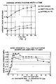
- drying cracking width of fibrous concrete is lower than that of the plain concrete, and fibre surface modification can improve crack controlling capacity of the fibres, as is evident from Table 3. This is probably due to the stronger adhesion between the PP fibre and concrete matrix by surface modification improving the crack bridging capacity of the PP fibres.
- the relationship between the drying cracking width and ageing time is shown in Figure 2.
- the PP fibre surface modification improves the interfacial bonding between the PP fibre and cementitious matrix and interfacial shear bond strength increased from 0,34 to 0,38 MPa.
- the shear bond strength - pull out slip curves of surface modified PP fibre compared with unmodified PP fibre are shown in Figure 3.
- the effect of mixing ratios on the interfacial bonding is indicated in Tables 4 and 5, and shear bond strength - pull out slip curves of different matrix mixing ratios are presented in Figures 4 and 5. It can be seen that high cement/aggregate ratio (rich concrete matrix) benefits the interfacial bonding since the interface become more dense. At low water/cement ratio, the flowability of the concrete is poor and thus the ability of concrete matrix to wrap the fibre is reduced. Under high water/cement ratio, the concrete matrix become more porous and intimate interfacial bonding can not be established. Water/cement ratios of between 0,40 and 0,50 thus appear to be the optimum for good interfacial bonding.
- Impact resistance test results are shown in Figure 6. Higher fibre volume fractions benefit impact resistance. Strong interfacial bonding between the fibre and matrix by surface modification benefits load bearing capacity in the post crack zone and thus the performance of FRC under dynamic loading, such as drop-weight impact, is improved.
- Flexural strengths of UMPP and MPP fibres FRC are substantially the same as those of plain concrete, as shown in Figure 7, which is based on the average of three samples.
- the flexural strength -deflection curves are nearly linear, as shown in Figures 8 and 9, which are based on only one sample in each case. This is probably due to strong interfacial bondings between the MPP fibres and concrete which restrict the friction process between the fibre and matrix when the FRC is subjected to loading; this is the most important factor for FRC to have higher ductility.
- the micro interfacial structure of the UMPP and MPP fibres were investigated using scanning electronic microscope ('SEM'). The surfaces of the UMPP fibres and MPP fibres after pulled out from the concrete matrix were observed. More cement hydration products were attached to the MPP fibre surface, indicating strong interfacial adhesion, while the UMPP fibres exhibited smooth surfaces with little hydrated cement paste attached thereto. The interfaces of UMPP and MPP fibre FRC were also examined. It could readily be seen that intimate and dense interfacial bonding was established between the MPP fibre and matrix, while the interface between the UMPP fibre and matrix was loose.
Landscapes
- Engineering & Computer Science (AREA)
- Chemical & Material Sciences (AREA)
- Architecture (AREA)
- Structural Engineering (AREA)
- Ceramic Engineering (AREA)
- Civil Engineering (AREA)
- Chemical Kinetics & Catalysis (AREA)
- General Chemical & Material Sciences (AREA)
- Materials Engineering (AREA)
- Organic Chemistry (AREA)
- Curing Cements, Concrete, And Artificial Stone (AREA)
Applications Claiming Priority (3)
| Application Number | Priority Date | Filing Date | Title |
|---|---|---|---|
| ZA941497 | 1994-03-03 | ||
| ZA941497 | 1994-03-03 | ||
| US08/398,098 US5744257A (en) | 1994-03-03 | 1995-03-03 | Production of composites |
Publications (2)
| Publication Number | Publication Date |
|---|---|
| EP0670291A2 true EP0670291A2 (de) | 1995-09-06 |
| EP0670291A3 EP0670291A3 (de) | 1996-04-17 |
Family
ID=27016121
Family Applications (1)
| Application Number | Title | Priority Date | Filing Date |
|---|---|---|---|
| EP19950301392 Withdrawn EP0670291A3 (de) | 1994-03-03 | 1995-03-03 | Herstellung von Verbundmaterialien. |
Country Status (5)
| Country | Link |
|---|---|
| US (1) | US5744257A (de) |
| EP (1) | EP0670291A3 (de) |
| JP (1) | JPH0834649A (de) |
| CN (1) | CN1119143A (de) |
| ZA (1) | ZA951800B (de) |
Cited By (1)
| Publication number | Priority date | Publication date | Assignee | Title |
|---|---|---|---|---|
| WO2004039744A1 (ja) * | 2002-10-30 | 2004-05-13 | Hagihara Industries Inc. | セメント強化用ポリプロピレン繊維、ならびに該繊維を用いたセメント成形体、コンクリート構造物の施工方法、および吹き付けコンクリート工法 |
Families Citing this family (10)
| Publication number | Priority date | Publication date | Assignee | Title |
|---|---|---|---|---|
| EP1020220A1 (de) * | 1999-01-11 | 2000-07-19 | Mira Diagnostica GmbH | Neue Fluorgruppen enthaltendes hydrophobes Polymer |
| US20040109996A1 (en) * | 1999-01-11 | 2004-06-10 | Kapoustine Dmitri Valerjewich | New hydrophobic polymer comprising fluorine moieties |
| US6462142B1 (en) | 1999-11-03 | 2002-10-08 | Air Products And Chemicals, Inc. | Processes for improved surface properties incorporating compressive heating of reactive gases |
| US7541089B1 (en) | 2001-05-21 | 2009-06-02 | Cortec Corporation | Composition and method for preserving posttensioning cables in metal reinforced concrete structures |
| EP1640787B1 (de) * | 2003-06-20 | 2009-04-01 | Sharp Kabushiki Kaisha | Anzeige |
| JP2006096565A (ja) * | 2004-03-31 | 2006-04-13 | Hagihara Industries Inc | セメント補強繊維 |
| US20050222303A1 (en) * | 2004-04-06 | 2005-10-06 | Cernohous Jeffrey J | Compositions and methods for producing highly filled materials |
| CN110530722B (zh) * | 2019-10-15 | 2022-05-10 | 淮阴工学院 | 高延性水泥基材料单轴拉伸模具及试件制法和测试方法 |
| CN111551407A (zh) * | 2020-04-14 | 2020-08-18 | 清华大学 | 胶结双球形颗粒材料及其制备方法 |
| CN112047684B (zh) * | 2020-08-25 | 2022-05-10 | 佛山市广陆混凝土制品有限公司 | 一种耐腐蚀防渗混凝土材料及其制备方法 |
Family Cites Families (18)
| Publication number | Priority date | Publication date | Assignee | Title |
|---|---|---|---|---|
| IL31483A (en) * | 1968-02-02 | 1972-02-29 | British Resin Prod Ltd | Plastics containers for fuel storage |
| US3865615A (en) * | 1973-05-07 | 1975-02-11 | Air Prod & Chem | Non-thrombogenic plastics |
| US4020223A (en) * | 1974-01-17 | 1977-04-26 | Air Products And Chemicals, Inc. | Fluorination of polyolefin and polyacrylonitrile fibers |
| GB1524232A (en) * | 1975-07-24 | 1978-09-06 | Pilkington Brothers Ltd | Glass fibres for use as reinforcement in cement products |
| US4142032A (en) * | 1977-12-29 | 1979-02-27 | Union Carbide Corporation | Process for improving barrier properties of polymers |
| US4237156A (en) * | 1978-11-17 | 1980-12-02 | Phillips Petroleum Company | Fluorinated poly(arylene sulfides) |
| US4296151A (en) * | 1978-12-12 | 1981-10-20 | Phillips Petroleum Company | Fluorinated polymeric surfaces |
| US4264750A (en) * | 1979-08-01 | 1981-04-28 | Massachusetts Institute Of Technology | Process for fluorinating polymers |
| US4404256A (en) * | 1980-03-26 | 1983-09-13 | Massachusetts Institute Of Technology | Surface fluorinated polymers |
| US4508781A (en) * | 1982-06-07 | 1985-04-02 | The United States Of America As Represented By The Secretary Of Agriculture | Fluorination by inorganic fluorides in glow discharge |
| US4557945A (en) * | 1982-06-07 | 1985-12-10 | Toshiharu Yagi | Process for fluorination by inorganic fluorides in glow discharge |
| IT1188216B (it) * | 1985-12-23 | 1988-01-07 | Ausimont Spa | Polimeri fluorurati contenenti cariche e aventi migliorate proprieta' |
| EP0242793B1 (de) * | 1986-04-23 | 1993-03-03 | Mitsubishi Kasei Corporation | Bewehrungsfaser für Zement |
| JPS6374946A (ja) * | 1986-09-13 | 1988-04-05 | 日本鋪道株式会社 | 分散性がよいセメント系粉体組成物およびその製造法 |
| US4764405A (en) * | 1987-07-22 | 1988-08-16 | Air Products And Chemicals, Inc. | Method for increasing barrier properties of thermoplastic substrates |
| JPH01172249A (ja) * | 1987-12-25 | 1989-07-07 | Tosoh Corp | セメント配合用物質 |
| US4880879A (en) * | 1988-02-18 | 1989-11-14 | Air Products And Chemicals, Inc. | Abrasion resistant composite material and process for making the same |
| JPH0598565A (ja) * | 1991-10-02 | 1993-04-20 | Nobuatsu Watanabe | 炭素繊維強化セメント複合材 |
-
1995
- 1995-03-03 ZA ZA951800A patent/ZA951800B/xx unknown
- 1995-03-03 EP EP19950301392 patent/EP0670291A3/de not_active Withdrawn
- 1995-03-03 US US08/398,098 patent/US5744257A/en not_active Expired - Lifetime
- 1995-03-03 CN CN95102029A patent/CN1119143A/zh active Pending
- 1995-03-03 JP JP7083195A patent/JPH0834649A/ja active Pending
Cited By (2)
| Publication number | Priority date | Publication date | Assignee | Title |
|---|---|---|---|---|
| WO2004039744A1 (ja) * | 2002-10-30 | 2004-05-13 | Hagihara Industries Inc. | セメント強化用ポリプロピレン繊維、ならびに該繊維を用いたセメント成形体、コンクリート構造物の施工方法、および吹き付けコンクリート工法 |
| EP1580173A4 (de) * | 2002-10-30 | 2007-05-09 | Hagihara Ind | Polypropylenfaser für die zementverstärkung, mit der faserhergestellter geschalter zement, verfahren zur konstruktion einerbetonstruktur und spritzbetonierverfahren |
Also Published As
| Publication number | Publication date |
|---|---|
| JPH0834649A (ja) | 1996-02-06 |
| ZA951800B (en) | 1995-12-21 |
| CN1119143A (zh) | 1996-03-27 |
| US5744257A (en) | 1998-04-28 |
| EP0670291A3 (de) | 1996-04-17 |
Similar Documents
| Publication | Publication Date | Title |
|---|---|---|
| US5891374A (en) | Method of making extruded fiber reinforced cement matrix composites | |
| EP0262981B1 (de) | Verfahren zur Herstellung zementhaltiger Produkte | |
| Majumdar et al. | Glass fibre reinforced cement | |
| Maho et al. | Mechanical properties and electrical resistivity of multiwall carbon nanotubes incorporated into high calcium fly ash geopolymer | |
| US5744257A (en) | Production of composites | |
| EP0114518B1 (de) | Herstellung von faserbewehrten Zement-Schichtstoff-Gegenständen | |
| EP0261971B1 (de) | Faserverstärktes Zementmaterial und geformter Artikel, enthaltend das gehärtete Zementmaterial | |
| KR102237816B1 (ko) | 3d 콘크리트 프린팅용 sbr 라텍스 개질 폴리머 시멘트 혼합물 및 그의 제조방법 | |
| Haghi et al. | Applications of expanded polystyrene (EPS) beads and polyamide-66 in civil engineering, Part One: Lightweight polymeric concrete | |
| EP0921107A1 (de) | Mischung für Glasfaser bewehrte Betonformteile und Verfahren und Vorrichtung zur Herstellung solcher Formteile | |
| AU705501B2 (en) | Production of composites | |
| JPH06293546A (ja) | 水硬性無機質成形体の製造方法 | |
| EP0150002B1 (de) | Erhärtete stranggepresste Gegenstände aus mit Metallfasern bewehrtem hydraulischem Material und Verfahren zu ihrer Herstellung | |
| KR102786403B1 (ko) | Pcc 및 비정질 금속섬유를 혼용한 모르타르 조성물 | |
| JP2511443B2 (ja) | 軽量セメント製品の製造方法 | |
| US4174366A (en) | Method of making reinforced concrete | |
| JPH07300357A (ja) | 繊維補強セメント硬化体 | |
| JP2511437B2 (ja) | 軽量セメント製品 | |
| JP2002154853A (ja) | コンクリート補強材及びそれを用いたコンクリート成形体 | |
| JPH01320241A (ja) | セメント組成物 | |
| DE3110658A1 (de) | Verfahren zur herstellung eines nicht brennbaren leichten leichtbetons und danach erhaeltlicher formkoerper | |
| JPH01320244A (ja) | セメント組成物およびそれを用いたセメント成形体の製造方法 | |
| RU2232151C1 (ru) | Способ производства асбестоцементной плиты под фасад | |
| JPH05329823A (ja) | 水硬性無機質成形体の製造方法 | |
| JP2511442B2 (ja) | 軽量セメント製品の製造方法 |
Legal Events
| Date | Code | Title | Description |
|---|---|---|---|
| PUAI | Public reference made under article 153(3) epc to a published international application that has entered the european phase |
Free format text: ORIGINAL CODE: 0009012 |
|
| AK | Designated contracting states |
Kind code of ref document: A2 Designated state(s): AT BE CH DE DK ES FR GB IT LI NL PT SE |
|
| PUAL | Search report despatched |
Free format text: ORIGINAL CODE: 0009013 |
|
| AK | Designated contracting states |
Kind code of ref document: A3 Designated state(s): AT BE CH DE DK ES FR GB IT LI NL PT SE |
|
| 17P | Request for examination filed |
Effective date: 19961016 |
|
| 17Q | First examination report despatched |
Effective date: 19970115 |
|
| STAA | Information on the status of an ep patent application or granted ep patent |
Free format text: STATUS: THE APPLICATION IS DEEMED TO BE WITHDRAWN |
|
| 18D | Application deemed to be withdrawn |
Effective date: 19990122 |