EP0668491A2 - Lagereinstellung unter Verwendung eines Druckkraftsensors - Google Patents
Lagereinstellung unter Verwendung eines Druckkraftsensors Download PDFInfo
- Publication number
- EP0668491A2 EP0668491A2 EP95630008A EP95630008A EP0668491A2 EP 0668491 A2 EP0668491 A2 EP 0668491A2 EP 95630008 A EP95630008 A EP 95630008A EP 95630008 A EP95630008 A EP 95630008A EP 0668491 A2 EP0668491 A2 EP 0668491A2
- Authority
- EP
- European Patent Office
- Prior art keywords
- force sensor
- force
- race
- back face
- pads
- Prior art date
- Legal status (The legal status is an assumption and is not a legal conclusion. Google has not performed a legal analysis and makes no representation as to the accuracy of the status listed.)
- Withdrawn
Links
Images


Classifications
-
- G—PHYSICS
- G01—MEASURING; TESTING
- G01L—MEASURING FORCE, STRESS, TORQUE, WORK, MECHANICAL POWER, MECHANICAL EFFICIENCY, OR FLUID PRESSURE
- G01L5/00—Apparatus for, or methods of, measuring force, work, mechanical power, or torque, specially adapted for specific purposes
- G01L5/12—Apparatus for, or methods of, measuring force, work, mechanical power, or torque, specially adapted for specific purposes for measuring axial thrust in a rotary shaft, e.g. of propulsion plants
-
- F—MECHANICAL ENGINEERING; LIGHTING; HEATING; WEAPONS; BLASTING
- F16—ENGINEERING ELEMENTS AND UNITS; GENERAL MEASURES FOR PRODUCING AND MAINTAINING EFFECTIVE FUNCTIONING OF MACHINES OR INSTALLATIONS; THERMAL INSULATION IN GENERAL
- F16C—SHAFTS; FLEXIBLE SHAFTS; ELEMENTS OR CRANKSHAFT MECHANISMS; ROTARY BODIES OTHER THAN GEARING ELEMENTS; BEARINGS
- F16C19/00—Bearings with rolling contact, for exclusively rotary movement
- F16C19/52—Bearings with rolling contact, for exclusively rotary movement with devices affected by abnormal or undesired conditions
- F16C19/522—Bearings with rolling contact, for exclusively rotary movement with devices affected by abnormal or undesired conditions related to load on the bearing, e.g. bearings with load sensors or means to protect the bearing against overload
-
- F—MECHANICAL ENGINEERING; LIGHTING; HEATING; WEAPONS; BLASTING
- F16—ENGINEERING ELEMENTS AND UNITS; GENERAL MEASURES FOR PRODUCING AND MAINTAINING EFFECTIVE FUNCTIONING OF MACHINES OR INSTALLATIONS; THERMAL INSULATION IN GENERAL
- F16C—SHAFTS; FLEXIBLE SHAFTS; ELEMENTS OR CRANKSHAFT MECHANISMS; ROTARY BODIES OTHER THAN GEARING ELEMENTS; BEARINGS
- F16C19/00—Bearings with rolling contact, for exclusively rotary movement
- F16C19/54—Systems consisting of a plurality of bearings with rolling friction
- F16C19/546—Systems with spaced apart rolling bearings including at least one angular contact bearing
- F16C19/547—Systems with spaced apart rolling bearings including at least one angular contact bearing with two angular contact rolling bearings
- F16C19/548—Systems with spaced apart rolling bearings including at least one angular contact bearing with two angular contact rolling bearings in O-arrangement
-
- F—MECHANICAL ENGINEERING; LIGHTING; HEATING; WEAPONS; BLASTING
- F16—ENGINEERING ELEMENTS AND UNITS; GENERAL MEASURES FOR PRODUCING AND MAINTAINING EFFECTIVE FUNCTIONING OF MACHINES OR INSTALLATIONS; THERMAL INSULATION IN GENERAL
- F16C—SHAFTS; FLEXIBLE SHAFTS; ELEMENTS OR CRANKSHAFT MECHANISMS; ROTARY BODIES OTHER THAN GEARING ELEMENTS; BEARINGS
- F16C25/00—Bearings for exclusively rotary movement adjustable for wear or play
- F16C25/06—Ball or roller bearings
-
- G—PHYSICS
- G01—MEASURING; TESTING
- G01L—MEASURING FORCE, STRESS, TORQUE, WORK, MECHANICAL POWER, MECHANICAL EFFICIENCY, OR FLUID PRESSURE
- G01L5/00—Apparatus for, or methods of, measuring force, work, mechanical power, or torque, specially adapted for specific purposes
- G01L5/0009—Force sensors associated with a bearing
- G01L5/0019—Force sensors associated with a bearing by using strain gages, piezoelectric, piezo-resistive or other ohmic-resistance based sensors
-
- B—PERFORMING OPERATIONS; TRANSPORTING
- B60—VEHICLES IN GENERAL
- B60G—VEHICLE SUSPENSION ARRANGEMENTS
- B60G2204/00—Indexing codes related to suspensions per se or to auxiliary parts
- B60G2204/10—Mounting of suspension elements
- B60G2204/11—Mounting of sensors thereon
- B60G2204/115—Wheel hub bearing sensors
-
- F—MECHANICAL ENGINEERING; LIGHTING; HEATING; WEAPONS; BLASTING
- F16—ENGINEERING ELEMENTS AND UNITS; GENERAL MEASURES FOR PRODUCING AND MAINTAINING EFFECTIVE FUNCTIONING OF MACHINES OR INSTALLATIONS; THERMAL INSULATION IN GENERAL
- F16C—SHAFTS; FLEXIBLE SHAFTS; ELEMENTS OR CRANKSHAFT MECHANISMS; ROTARY BODIES OTHER THAN GEARING ELEMENTS; BEARINGS
- F16C19/00—Bearings with rolling contact, for exclusively rotary movement
- F16C19/22—Bearings with rolling contact, for exclusively rotary movement with bearing rollers essentially of the same size in one or more circular rows, e.g. needle bearings
- F16C19/34—Bearings with rolling contact, for exclusively rotary movement with bearing rollers essentially of the same size in one or more circular rows, e.g. needle bearings for both radial and axial load
- F16C19/36—Bearings with rolling contact, for exclusively rotary movement with bearing rollers essentially of the same size in one or more circular rows, e.g. needle bearings for both radial and axial load with a single row of rollers
- F16C19/364—Bearings with rolling contact, for exclusively rotary movement with bearing rollers essentially of the same size in one or more circular rows, e.g. needle bearings for both radial and axial load with a single row of rollers with tapered rollers, i.e. rollers having essentially the shape of a truncated cone
-
- F—MECHANICAL ENGINEERING; LIGHTING; HEATING; WEAPONS; BLASTING
- F16—ENGINEERING ELEMENTS AND UNITS; GENERAL MEASURES FOR PRODUCING AND MAINTAINING EFFECTIVE FUNCTIONING OF MACHINES OR INSTALLATIONS; THERMAL INSULATION IN GENERAL
- F16C—SHAFTS; FLEXIBLE SHAFTS; ELEMENTS OR CRANKSHAFT MECHANISMS; ROTARY BODIES OTHER THAN GEARING ELEMENTS; BEARINGS
- F16C2226/00—Joining parts; Fastening; Assembling or mounting parts
- F16C2226/50—Positive connections
- F16C2226/60—Positive connections with threaded parts, e.g. bolt and nut connections
-
- F—MECHANICAL ENGINEERING; LIGHTING; HEATING; WEAPONS; BLASTING
- F16—ENGINEERING ELEMENTS AND UNITS; GENERAL MEASURES FOR PRODUCING AND MAINTAINING EFFECTIVE FUNCTIONING OF MACHINES OR INSTALLATIONS; THERMAL INSULATION IN GENERAL
- F16C—SHAFTS; FLEXIBLE SHAFTS; ELEMENTS OR CRANKSHAFT MECHANISMS; ROTARY BODIES OTHER THAN GEARING ELEMENTS; BEARINGS
- F16C2229/00—Setting preload
-
- F—MECHANICAL ENGINEERING; LIGHTING; HEATING; WEAPONS; BLASTING
- F16—ENGINEERING ELEMENTS AND UNITS; GENERAL MEASURES FOR PRODUCING AND MAINTAINING EFFECTIVE FUNCTIONING OF MACHINES OR INSTALLATIONS; THERMAL INSULATION IN GENERAL
- F16C—SHAFTS; FLEXIBLE SHAFTS; ELEMENTS OR CRANKSHAFT MECHANISMS; ROTARY BODIES OTHER THAN GEARING ELEMENTS; BEARINGS
- F16C2326/00—Articles relating to transporting
- F16C2326/01—Parts of vehicles in general
- F16C2326/02—Wheel hubs or castors
Definitions
- This invention relates in general to bearings which take axial as well as radial loads and force sensing devices suitable for use in adjusting such bearings, and, more particularly, to a process for adjusting such bearings using a compressive force sensor, to a bearing assembly containing a compressive force sensor, and to a compressive force sensor itself.
- Some antifriction bearings which utilize rolling elements of one type or another between concentric races, have the capacity to transfer axial or thrust loads as well as radial loads, and when single row bearings of this character are organized in pairs, one opposing the other, they are well suited for a wide variety of machine applications, not the least of which is in mountings for the road wheels of automotive vehicles. But the bearings, when so organized, require adjustment during installation to achieve the proper setting for operation. If they are set with too much end play, a limited amount of free radial and axial motion exists in the mounting which may manifest itself in wheel wobble. This instability detracts from the performance of the seals that protect such bearings from contaminants.
- Preload on the other hand, produces a very rigid mounting, but also imparts more friction, and while too much preload may cause the bearings to fail early, a light preload extends bearing life and enhances seal performance.
- the end play is measured using a dial indicator.
- the mechanic installs the indicator on the wheel with its stylus against the spindle end and moves the wheel axially back and forth while oscillating it, observing the reading on the indicator as he does, the reading so derived being the end play. If excessive end play appears, the mechanic backs the jam nut off, advances the spindle nut slightly, with the amount being largely based on experience, tightens the jam nut, and makes another measurement. If insufficient end play exists, the mechanic follows essentially the same procedure, but backs the spindle nut off instead of turning it down. This trial and error procedure is repeated until the measured end play falls within an acceptable range.
- the present invention resides in a process for quickly adjusting bearings without resorting to trial and error techniques. It enables bearings to be set with a known and controlled preload, all quite easily and in minimum time.
- the process utilizes a force sensor which is embodied in the bearing arrangement itself, but occupies only a very small amount of space.
- the invention also resides in the bearing arrangement having the force sensor incorporated into it and in the force sensor itself.
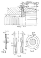
- the present invention resides in a bearing assembly A (Fig. 1) that enables one machine component to rotate relative to another machine component about an axis X, which of course coincides with the axis of the bearing assembly A, and also in a procedure for adjusting the bearing assembly A.
- the one machine component constitutes a spindle 2
- the other is a hub 4 and the two form part of the bearing assembly.
- the bearing assembly A includes two single row tapered roller bearings 6 and 8, each of which fits over the spindle 2 and within the hub 4. Here they are mounted in opposition, so that the inboard bearing 6 takes thrust loads in one axial direction and the outboard bearing 8 takes thrust loads in the opposite axial direction.
- the spindle 2 is part of the suspension system of an automotive vehicle and the hub 4 has a road wheel 10 attached to it.
- the bearing assembly A has the capacity to sense a clamping force that is transmitted through its bearings 6 and 8, and thus facilitates adjustment of the bearing assembly A and enables it to be brought to the proper setting with considerable precision.
- the spindle 2 has two cylindrical bearing seats 12 (Fig. 1) of different diameters.
- the inboard seat 12 which is larger in diameter than the outboard seat 12, projects from a shoulder 14, whereas a threaded end 16 extends beyond the smaller seat 12.
- the threaded end 16 contains an axially directed slot or groove 17.
- the two bearings 6 and 8 fit around the seats 12.
- the hub 4 fits over the spindle 2 and receives the two bearings 6 and 8 in counterbores 18 (Fig. 1) which open out of its ends. Each counterbore 18 terminates at a shoulder 20.
- the hub 4 has outwardly directed flanges 22 to which the road wheel 10 and a brake drum 26 are attached with machine bolts 28.
- the hub 4 is further provided with a seal 30 which embraces the spindle 2 to establish a dynamic fluid barrier along the spindle 2.
- the hub 4 is fitted with an end cap 32.
- the seal 30 and end cap 32 isolate the interior of the hub 4 and thereby protect the bearings 6 and 8 located in it.
- Each bearing 6 and 8 being a single row tapered roller bearing, has an inner race or cone 34 (Fig. 1), an outer race or cup 36 and tapered rollers 38 arranged in a single circumferential row between the cone 34 and cup 36.
- the tapered side faces of the rollers 38 contact the cone 34 and cup 36 along tapered raceways 40, and those raceways 40 are on apex, meaning that if the raceways 40 were extended to their respective apexes, those apexes would for all intents and purposes lie at a common point along the axis X.
- the cone 34 and cup 36 each have a back face 42, with the back face 42 of the cone 34 being beyond the large end in the cone raceway 40 and the back face 42 of the cup 36 being at the small end of the cup raceway 40.
- the back faces 42 for the cone 34 and cup 36 of either bearing 6 or 8 are presented in opposite directions - and well they should, for they represent the surfaces at which thrust loads are applied to the bearing 6 or 8.
- each bearing 6 and 8 has a cage 44 for maintaining the proper spacing between the rollers 38 and for holding the rollers 38 around the cone 34 when the cone 34 is withdrawn from the cup 36.
- the cone 34 of the inboard bearing 6 fits over the large bearing seat 12 with a slight clearance fit, its back face 42 being against the shoulder 14 at the end of that seat (Fig. 1).
- the cup 36 for the inboard bearing 6 fits into the inboard counterbore 18 in the hub 4 with its back face 42 against the shoulder 20 at the inner end of that counterbore 18.
- the cup 36 of the outboard bearing 8 fits into the outboard counterbore 18 of the hub 4 with its back face 42 against the shoulder 20 of that counterbore. Indeed, the two cups 36 are pressed into their respective counterbores 18, so that an interference fit exists between the hub 4 and the two cups 36, and the cups 36 and their raceways 40 are in effect fixed in position in the hub 4.
- the cone 34 of the outboard bearing 8 fits over the outboard bearing seat 12 on the spindle 2 with a slight clearance fit, its back face 42 being presented toward the threaded end 16 of the spindle 2.
- the bearings 6 and 8 when sc oriented, create an indirect mounting - and an indirect bearing mounting will accommodate axial loads in either axial direction, as well as radial loads.
- the two bearings 6 and 8 are held on the spindle 2 by a nut 46 (Figs. 1 & 2) which threads over the threaded end 16 and is turned down against a washer 48, which in turn confronts the back face 42 of the outboard cone 34 to position that cone.
- Some type of locking device also fits over the threaded end 16 of the spindle 2 to restrain the nut 46 and indeed hold it in the position to which it is turned during installation, for after all the position of the nut 46 on the threaded end 16 of the spindle 2 determines the setting for the two bearings 6 and 8. If the nut 46 is turned down too far, the clamping force imparted by it will drive the rollers 38 too tightly between the tapered raceways 40 and thereby impose an excessive preload.
- the washer 48 performs the traditional function of spreading the clamping force exerted by the nut 46 more uniformly across the back face 42 of the outboard cone 34. It further has a tongue 50 (Figs. 2 & 3) which fits into the groove 17 of the spindle 2, so that the washer 48 will not rotate on the threaded end 16 of the spindle 2.
- the outboard cone 34 has a tendency to creep when the hub 4 revolves, and the washer 48 being incapable of rotating, isolates the nut 46 from the creep of cone 34, so the cone 34 does not turn the nut 46.
- the washer 50 carries a force sensor 52 that has the capacity to monitor the magnitude of the force transmitted axially through the washer 48, making it possible to determine the clamping force exerted by the nut 46 on the cones 34 of the two bearings 6 and 8 and transmitted through the bearings 6 and 8 into and through the hub 4. That clamping force, of course, represents the preload in the bearings 6 and 8, so the washer 48 and its force sensor 52 are useful in adjusting the bearings 6 and 8 to a desired condition of preload - and the bearings 6 and 8 operate best under light preload.
- That end of the washer 48 which is presented toward the nut 46 is perfectly flat, that is to say planar, with its surface perpendicular to the axis X of the spindle 2 and bearings 6 and 8.
- the other end contains a shallow, yet wide groove in the form of a rabbet thus presenting two faces toward the back face 42 of the outboard cone 34 (Figs. 2 & 3), one being an end or abutment face 54 at the groove and the other being an auxiliary face 56 located closer to the back face 42 of the nearby cone 34.
- the two faces, both of which are planar and lie in planes perpendicular to the axis X, are offset a distance d (Fig. 2).
- the abutment face 54 has a radial dimension r.
- the force sensor 52 lies along the abutment face 54 as do two spacers 58, all being arranged at equal circumferential intervals and held against the face 54 with an adhesive.
- Each possesses the same thickness h which is slightly greater than the offset d between the faces 54 and 56, so that the sensor 52 and spacers 58 project axially beyond the auxiliary face 56 of the washer 48.
- the washer 48 does not actually contact the back face 42 of the outboard cone 34; instead, the force sensor 52 and spacers 58 do.
- the clamping force exerted by the nut 46 is transferred to the outboard cone 34 through the washer 48 and the force sensor 52 and spacers 58, and this holds true through all magnitudes of preload under which the bearings 6 and 8 may be expected to operate.
- the thickness h of the force sensor 52 and spacers 56 is 0.013 inches and the offset between the faces 54 and 56 is 0.012 inches.
- the radial dimension r of the abutment face 54 to a large measure depends on the size of the bearing 6, but where the bearing 6 is on the spindle for the axle of a heavy truck or trailer, the dimension r is about 0.25 inches.
- the force sensor 52 consists of two thin pads 60 and 62 (Figs. 4 & 5) and a foil strain gage element 64 interposed between the two pads 60 and 62.
- Each of the pads 60 and 62 is derived from a film of somewhat elastic polymer, such Mylar or polyvinylchloride, which when compressed between flat surfaces is capable of expanding or extruding transversely with respect to the direction of the compressive force.
- Each, moreover, is about 0.002 to 0.008 inches thick and preferably about 0.006 inches, with its exterior dimension being that of the sensor 52 itself.
- Each pad 60 has an adhesive on one of its faces.
- the foil strain gage element 64 is commercially available. It consists of polymer film onto which a metal, such as iron constantan, is deposited onto one of its faces. The element is about .001 inches thick and is organized in zigzag configuration with parallel legs 66 (Fig. 5) and short connecting segments 68 joining the ends of adjacent legs 66 (Fig. 5). Twelve or more legs 66 may exist in the array. The two legs 66 at the sides of the array project beyond the ends of the remaining legs 66 and are connected to leads 70 to which instrumentation may be connected.
- the foil strain gage element 64 is smaller than the pads 60 and 62 (Fig. 5). Indeed, the two pads 60 and 62 are brought together with the adhesive-coated face on the pad 62 presented toward uncoated surface of the pad 60 and with their margins in registration and further with the foil element 64 interposed between them, its outermost legs 66 being set inwardly from the side margins of the pads 60 and 62 and its connecting segments 68 being set inwardly from the end margins of the pads 60 and 62.
- the adhesive coatings on the pad 62 bonds the two pads 60 and 62 together and in effect encapsulate the foil element 64 between them.
- the leads 70 project outwardly beyond the registered margins of the pads 60 and 62 at one side of the cell 52.
- the adhesive on the other face of the pad 60 holds the entire sensor 52 against the abutment face 54 of the washer 48.
- the force sensor 52 projects beyond the auxiliary face 56 of the washer 48 with its pad 62 being presented toward the back face 42 of the outboard cone 34 (Fig. 2).
- the sensor 52 lies captured between the washer 48 and the cone 34 with its pad 60 against the abutment face 54 on the washer 48 and its pad 62 against the back face 42 of the cone 34.
- the spacers 58 lie between the same surfaces at 120° intervals and simply prevent the washer 48 from cocking owing to the presence of the load cell 52 (Fig 3). In this regard, the spacers 58 possess essentially the same thickness h and elastic properties as the force sensor 52.
- the outboard cone 34 and its complement of rollers 38 are passed over the spindle 2 and into the outboard cup 36 with the back face of the cone 34 presented away from the interior of the hub 4.
- the washer 48 is installed over the threaded end 16 of the spindle 2, with the force sensor 52 and spacers 58 presented toward the outboard cone 34.
- the nut 46 is engaged with the threads of the threaded end 16 and turned down lightly against the washer 48.
- the two bearings 6 and 8 exist in a condition of end play - a condition characterized by free motion, both axially and radially in the hub 4. But as the nut 46 is advanced further over the threaded end 16 of the spindle 2, it drives the cone 34 of the outboard bearing 8 toward the cone 34 of the inboard bearing 6, thereby reducing the end play. Eventually, the bearings 6 and 8 reach a neutral condition, known as zero end play, in which they have no end play and no preload.
- the force sensor 52 being formed for the most part from polymer, yields under the clamping force transmitted to it through the aubtment face 54 of the washer 48 and the back face 42 of the outboard cone 34, and that force of course derives from the nut 46 which is turned down over the threaded end 16 of the spindle 2.
- the thickness h of the sensor 52 decreases. This change in the thickness h translates into an increase in the length and width of the pads 60 and 62, that is to say the pads 60 and 62 extrude parallel to the axis y (Fig. 5) of the foil element 64 and transverse to that axis as well.
- the decrease in the thickness h and the lateral extrusion remain within the elastic limits of the polymer from which the pads 60 and 62 are derived.
- the foil element 64 being clamped between the two pads 60 and 62, undergoes the same expansion.
- the expansion along the major axis y of the foil element 64 lengthens the legs 66 of the element 64, and this in turn alters the electrical resistance of each leg 66 of the element 64, for it is a well-known characteristic of metal to change resistance when elongated. Since the legs 66 lie in series, their elongation in the presence of the extrusion produces a more pronounced change in the electrical resistance of the entire foil element 64.
- the correlation between compressive force applied to the force sensor 52 and the electrical resistance of its foil element 64 may be plotted on cartesian coordinates.
- One can measure the increase in the resistance of the foil element 64 simply by connecting suitable instrumentation to the leads 70 that are exposed on the force sensor 52.
- suitable instrumentation to the leads 70 that are exposed on the force sensor 52.
- the locking device is a jam nut threaded over the end 16 and against the adjusting nut 46, it will displace the nut 46 toward the bearing 8, owing to the tolerances between the threads of the nut 46 nd the end 16, and this displacement will impose a greater preload in the bearings 6 and 8. But the force sensor 52 will detect this increase in preload, and the nut 46 may be backed off slightly to accommodate the displacement produced by the jam nut.
- the force sensor 52 and the spacers 58 remain in place when the bearing assembly A, once adjusted, is set in operation. But the bearings 6 and 8 and the brake drum 26 generate heat, and the heat degrades the adhesives which holds the force sensor 52 and spacers 58 in place. Then there is the grease which lubricates the bearings 6 and 8. It migrates out onto the washer 48 and further degrades the adhesives. Finally, during the operation of the bearings 6 and 8, the two cones 34, having been installed with a slight clearance fit, creep on the spindle 2, and this rotation tends to tear the force sensor 52 and spacers 58 from the washer 48.
- the force sensor 52 and the spacers 58 may be attached to the back face 42 of the outboard cone 34 such that they align with the abutment face 54 on the washer 48. They may also be installed between the shoulder 14 and the back face 42 of the inboard cone 34. Then again, if the cups 36 are fitted to their respective counterbores 18 in the hub 4 with clearance fits, the force sensor 52 and spacers 58 may be fitted between the back face 42 of either one of the cups 36 and the shoulder 20 toward which the cup 36 is presented. But the location between the washer 48 and the outboard cone 34 is the most convenient for indirectly mounted bearings on dead spindles. For directly mounted bearings, the outboard cup would be most accessible, so the force sensor 52 should be between its back face and the abutment toward which that face is presented.
- the force sensor 52 enables the bearings 6 and 8 to be adjusted into a condition of preload with considerably more precision than past procedures. Moreover, the procedure requires very little effort and only minimal skills. It is virtually foolproof. The procedure lends itself to factory assembly operations or subsequent maintenance procedures all without requiring modifications in the spindle 2, hub 4 or bearings 6 and 8. Being extremely thin and small, the force sensor 52 easily fits into bearing arrangements of current manufacture.
- Bearings other than tapered roller bearings may be adjusted using the force sensor 52, but such bearings should have angular raceways so as to be capable of taking axial as well as radial loads. Also, the force sensor used to monitor the clamping force may rely on other electrical characteristics such as capacitance.
- the procedure may be used to adjust the bearings 6 and 8 to a condition of end play.
- a spacer of known thickness is installed between the force sensor 52 and the back face 42 of the outboard cone 34.
- the spacer is not permanent, but instead, will disintegrate when subjected to elevated temperatures or perhaps a solvent.
- the nut 46 is tightened until the force sensor 52 registers a desired load, and then the nut 46 is secured.
- the bearings 6 and 8 exist in a condition of preload. But then the end of the spindle 2 is heated or subjected to a treatment that eliminates the spacer that is behind the force sensor 52. This transforms the setting to one of known end play.
- a modified bearing assembly B (Fig. 6) likewise has bearings 6 and 8 which fit between a spindle 2 and a hub 4 in the indirect configuration and enable the hub 4 to rotate relative to the spindle 2 about an axes X.
- the spindle 2 has a threaded end 16 which leads up to the back face 42 on the cone 34 of the outboard bearing 8.
- the similarities between the bearing assemblies A and B end in that the bearing assembly B relies on a flowing fluid for its adjustment.
- the bearing assembly B has a force sensor 78 which includes a nut 80 that is engaged with the threaded end 16 on the spindle 2 and has an end face 82 which is squared off with respect to the axis X and is presented toward the back face 42 of the outboard cone 34.
- the nut 80 also contains an annular groove 84 which opens out of the end face 82, it having its center at the axis X and being set inwardly from the periphery of the face 82. Within the nut 80, the annular groove 84 communicates with a feed channel 86 which extends axially to the opposite end of the nut 80 out of which it opens.
- the nut 80 does not contact the back face 42 of the outboard cone 34, but is instead held away from the cone 34 by compression ring 88 which is located between the end face 82 of the nut 80 and the back face 42 of the cone 34, it also forming part of the force sensor 78.
- the ring 88 encircles the spindle 2, but has a diameter less than the groove 84, so that it does not obstruct the groove 84.
- a gap exists between the back face 42 of the outboard cone 34 and the end face 82 of the nut 80, that gap having a width g.
- As the nut 80 is turned down over the threaded end 16, it compresses the ring 88, first plastically and then elastically, and with this compression the width g of the gap narrows, but the gap is never entirely eliminated.
- the axial feed channel 86 in the nut 80 is connected to a feed tube 90 which contains a restriction 92, and beyond the restriction the feed tube 90 is connected to a source of compressed air. Downstream from the restriction 92 a pressure gage 94 is connected to the feed tube 90 to monitor the pressure in the feed tube 92.
- the compressive force and the pressure are related and may be plotted against each other to provide a graph.
- the bearing assembly B To set the bearing assembly B to a desired preload, one simply turns the nut 80 down over the threaded end 16 of the spindle 2, while directing pressurized air through the feed tube 90 and channel 86. The air escapes through the gap between the back face 42 of the outboard cone 34 and the end face 82 of the nut 80, but the gap restricts the flow and produces back pressure in the fluid.
- the gage 94 registers that back pressure.
- the assembler monitors the pressure registered by the gage 94, and may rotate hub 4 contemporaneously to insure that the rollers 38 of the two bearings 6 and 8 seat properly along the raceways 40.
- the nut 80 is advanced until the pressure registered at the gage 94 correlates with the desired preload for the bearings 6 and 8.
Landscapes
- Engineering & Computer Science (AREA)
- General Engineering & Computer Science (AREA)
- Mechanical Engineering (AREA)
- Chemical & Material Sciences (AREA)
- Physics & Mathematics (AREA)
- General Physics & Mathematics (AREA)
- Analytical Chemistry (AREA)
- Combustion & Propulsion (AREA)
- Support Of The Bearing (AREA)
- Rolling Contact Bearings (AREA)
- Force Measurement Appropriate To Specific Purposes (AREA)
Applications Claiming Priority (2)
| Application Number | Priority Date | Filing Date | Title |
|---|---|---|---|
| US08/195,698 US5488871A (en) | 1994-02-16 | 1994-02-16 | Bearing adjustment using compressive force sensor |
| US195698 | 1994-02-16 |
Publications (2)
| Publication Number | Publication Date |
|---|---|
| EP0668491A2 true EP0668491A2 (de) | 1995-08-23 |
| EP0668491A3 EP0668491A3 (de) | 1996-01-17 |
Family
ID=22722411
Family Applications (1)
| Application Number | Title | Priority Date | Filing Date |
|---|---|---|---|
| EP19950630008 Withdrawn EP0668491A3 (de) | 1994-02-16 | 1995-02-09 | Lagereinstellung unter Verwendung eines Druckkraftsensors. |
Country Status (3)
| Country | Link |
|---|---|
| US (1) | US5488871A (de) |
| EP (1) | EP0668491A3 (de) |
| JP (1) | JPH07332360A (de) |
Cited By (11)
| Publication number | Priority date | Publication date | Assignee | Title |
|---|---|---|---|---|
| US6289749B1 (en) | 1997-08-01 | 2001-09-18 | Rotork Controls Limited | Thrust sensor assembly |
| WO2002057730A1 (de) * | 2001-01-19 | 2002-07-25 | Robert Bosch Gmbh | Nebenschlussfreie erfassung einer messgrösse an einem beschleunigten bauteil an einem radiallager (felge an radlager) |
| WO2003019126A1 (de) | 2001-08-23 | 2003-03-06 | Knorr-Bremse Systeme für Nutzfahrzeuge GmbH | Einrichtung zur ermittlung von auf die radaufhängung eines rades eines fahrzeuges einwirkenden kräften und/oder momenten |
| WO2001077634A3 (en) * | 2000-04-10 | 2003-08-28 | Timken Co | Bearing assembly with sensors for monitoring loads |
| EP1262676A3 (de) * | 2001-05-31 | 2004-06-16 | AEA Technology plc | Kraftverstärkungsmechanismus |
| EP1818660A1 (de) | 2004-11-22 | 2007-08-15 | JTEKT Corporation | Auf einem Sensor montierte Kugellagervorrichtung |
| USRE39838E1 (en) | 2000-04-10 | 2007-09-18 | The Timken Company | Bearing assembly with sensors for monitoring loads |
| CN102135134A (zh) * | 2011-03-25 | 2011-07-27 | 浙江兆丰机电股份有限公司 | 汽车轮毂轴承单元 |
| US20160208851A1 (en) * | 2015-01-16 | 2016-07-21 | George A. Hagelthorn | System and method for measuring pre-load force during tapered roller bearing wheel adjustment |
| US9970486B2 (en) | 2015-01-16 | 2018-05-15 | George A. Hagelthorn | System and method for measuring pre-load force during tapered roller bearing wheel adjustment |
| US10975909B1 (en) | 2020-02-03 | 2021-04-13 | George A. Hagelthorn | System and method to precisely adjust tapered roller bearings using a four-piece jam nut configuration |
Families Citing this family (22)
| Publication number | Priority date | Publication date | Assignee | Title |
|---|---|---|---|---|
| US6058767A (en) * | 1998-02-27 | 2000-05-09 | The Timken Company | Measurement of wheel bearing end play |
| US5996408A (en) * | 1998-09-17 | 1999-12-07 | Chrysler Corporation | Wheel speed sensor with stand-off tabs |
| US6334713B1 (en) | 1999-03-23 | 2002-01-01 | Roller Bearing Industries, Inc. | Bearing assembly having an improved wear ring liner |
| AU6908900A (en) | 1999-08-16 | 2001-03-13 | Roller Bearing Industries, Inc. | Bearing seal |
| US6490935B1 (en) * | 1999-09-28 | 2002-12-10 | The Timken Company | System for monitoring the operating conditions of a bearing |
| US6802208B2 (en) * | 2002-03-04 | 2004-10-12 | Delphi Technologies, Inc. | Vehicle wheel bearing and method for controlling a vehicle |
| US6776261B2 (en) | 2002-05-29 | 2004-08-17 | Garlock Sealing Technologies Llc | Lubricant monitoring system |
| EP1666860B1 (de) * | 2003-08-29 | 2011-12-28 | Jtekt Corporation | Hub-einheit mit sensor |
| DE602005024368D1 (de) * | 2004-02-18 | 2010-12-09 | Ntn Toyo Bearing Co Ltd | Lagervorrichtung für rad |
| US7628540B2 (en) * | 2004-02-18 | 2009-12-08 | Ntn Corporation | Bearing device for wheel |
| US7665372B2 (en) * | 2005-04-27 | 2010-02-23 | Jtekt Corporation | Rolling bearing device with sensor and strain sensor |
| US7878713B2 (en) * | 2005-08-22 | 2011-02-01 | Ntn Corporation | Sensor-equipped bearing for wheel |
| US8028589B2 (en) * | 2007-01-17 | 2011-10-04 | Ntn Corporation | Sensor-equipped bearing for wheel |
| DE102007010314A1 (de) | 2007-02-24 | 2008-08-28 | Sauer-Danfoss Aps | Verfahren zum Herstellen und/oder Montieren von Lagereinrichtungen |
| US8342039B2 (en) * | 2010-03-12 | 2013-01-01 | Wickens Jeffrey S | Process for measuring preloading of low-rolling resistance bearings |
| US9092576B2 (en) * | 2010-06-25 | 2015-07-28 | International Business Machines Corporation | Non-intrusive measurement of content quality using dry runs with roll-back |
| DE102014213878B4 (de) * | 2014-07-16 | 2021-12-23 | Aktiebolaget Skf | Verfahren zur Einstellung der Vorspannung in einer Lageranordnung und Lageranordnung |
| US9891136B2 (en) | 2015-09-30 | 2018-02-13 | Deere & Company | Methods to determine a bearing setting |
| DE102017111745A1 (de) * | 2017-05-30 | 2018-12-06 | Schaeffler Technologies AG & Co. KG | Wälzlageranordnung für ein Getriebe |
| TWI676522B (zh) * | 2018-07-26 | 2019-11-11 | 財團法人精密機械研究發展中心 | 監測主軸軸承預壓值的方法、定量地界定主軸的溫度與主軸軸承預壓值之間的關係的方法、定量地界定主軸的轉速與主軸軸承預壓值之間的關係的方法以及透過資料庫來界定最佳的主軸軸承預壓值的方法 |
| JP7149155B2 (ja) * | 2018-10-09 | 2022-10-06 | Ntn株式会社 | 軸受装置 |
| US12411050B1 (en) * | 2024-05-22 | 2025-09-09 | Bpg-Arrowhead Winch Inc. | Radial load measuring apparatus |
Family Cites Families (23)
| Publication number | Priority date | Publication date | Assignee | Title |
|---|---|---|---|---|
| US2636964A (en) * | 1953-04-28 | Transducer | ||
| US2090188A (en) * | 1933-10-03 | 1937-08-17 | Morgan Construction Co | Measurement of pressures |
| US2133230A (en) * | 1937-08-12 | 1938-10-11 | Timken Roller Bearing Co | Axle bearing seal |
| US3036283A (en) * | 1960-05-27 | 1962-05-22 | Lockheed Aircraft Corp | Load cell transducer |
| US3151480A (en) * | 1960-08-10 | 1964-10-06 | United States Steel Corp | Load cell |
| US3313151A (en) * | 1965-07-26 | 1967-04-11 | Freightliner Corp | Load cell |
| US3358257A (en) * | 1965-12-27 | 1967-12-12 | Lockheed Aircraft Corp | Force and moment transducer |
| DE1932899A1 (de) * | 1969-06-28 | 1971-01-07 | Rohrbach Dr Christof | Messwertgeber zum Umwandeln von Kraeften,mechanischen Spannungen oder Druecken in elektrische Widerstandsaenderungen |
| DE2146339B2 (de) * | 1971-09-16 | 1975-04-03 | Industrie-Automation Gmbh & Co, 6900 Heidelberg | Elektromechanischer Kraft- oder Druckmeßwandler |
| DE2746937C2 (de) * | 1977-10-17 | 1986-11-06 | Gerhard Dr.-Ing. 1000 Berlin Lechler | Kraftmeßeinrichtung |
| US4175429A (en) * | 1978-03-13 | 1979-11-27 | Betriesbsforschungsinstitut VDEh Institut fur angewandte Forschung GmbH | Device for the measurement of forces or pressures |
| CH631013A5 (de) * | 1978-09-20 | 1982-07-15 | Schmid Roost J Sro Kugellagerw | Messvorrichtung. |
| DE2911479C2 (de) * | 1979-03-22 | 1983-09-29 | Lechler, Gerhard, Dr.-Ing., 1000 Berlin | Kraftmeßeinrichtung |
| US4763534A (en) * | 1985-01-31 | 1988-08-16 | Robert G. Fulks | Pressure sensing device |
| US4856993A (en) * | 1985-03-29 | 1989-08-15 | Tekscan, Inc. | Pressure and contact sensor system for measuring dental occlusion |
| US4734034A (en) * | 1985-03-29 | 1988-03-29 | Sentek, Incorporated | Contact sensor for measuring dental occlusion |
| US4762011A (en) * | 1987-04-16 | 1988-08-09 | General Motors Corporation | Electronic gage |
| US5009523A (en) * | 1989-07-20 | 1991-04-23 | The Timken Company | Double row bearing assembly |
| DE4011314A1 (de) * | 1990-04-07 | 1991-10-10 | Hottinger Messtechnik Baldwin | Dehnungsmessstreifen und messgroessenaufnehmer mit derartigen dehnungsmessstreifen |
| US5140849A (en) * | 1990-07-30 | 1992-08-25 | Agency Of Industrial Science And Technology | Rolling bearing with a sensor unit |
| DE9103935U1 (de) * | 1991-03-30 | 1991-06-27 | J.M. Voith Gmbh, 7920 Heidenheim | Lagergehäuse für ein mehrreihiges Wälzlager oder für mehrere koaxial nebeneinander liegende Wälzlager |
| US5085519A (en) * | 1991-07-05 | 1992-02-04 | The Timken Company | Bearing assembly with speed sensor and process for assembling the same |
| NL9101579A (nl) * | 1991-09-19 | 1993-04-16 | Skf Ind Trading & Dev | Werkwijze voor het tot een bepaalde voorbelasting aanschroeven van een van schroefdraad voorzien element. |
-
1994
- 1994-02-16 US US08/195,698 patent/US5488871A/en not_active Expired - Fee Related
-
1995
- 1995-02-08 JP JP7020794A patent/JPH07332360A/ja active Pending
- 1995-02-09 EP EP19950630008 patent/EP0668491A3/de not_active Withdrawn
Cited By (14)
| Publication number | Priority date | Publication date | Assignee | Title |
|---|---|---|---|---|
| US6289749B1 (en) | 1997-08-01 | 2001-09-18 | Rotork Controls Limited | Thrust sensor assembly |
| USRE39838E1 (en) | 2000-04-10 | 2007-09-18 | The Timken Company | Bearing assembly with sensors for monitoring loads |
| WO2001077634A3 (en) * | 2000-04-10 | 2003-08-28 | Timken Co | Bearing assembly with sensors for monitoring loads |
| WO2002057730A1 (de) * | 2001-01-19 | 2002-07-25 | Robert Bosch Gmbh | Nebenschlussfreie erfassung einer messgrösse an einem beschleunigten bauteil an einem radiallager (felge an radlager) |
| EP1262676A3 (de) * | 2001-05-31 | 2004-06-16 | AEA Technology plc | Kraftverstärkungsmechanismus |
| WO2003019126A1 (de) | 2001-08-23 | 2003-03-06 | Knorr-Bremse Systeme für Nutzfahrzeuge GmbH | Einrichtung zur ermittlung von auf die radaufhängung eines rades eines fahrzeuges einwirkenden kräften und/oder momenten |
| EP1818660A1 (de) | 2004-11-22 | 2007-08-15 | JTEKT Corporation | Auf einem Sensor montierte Kugellagervorrichtung |
| US7497131B2 (en) | 2004-11-22 | 2009-03-03 | Jtekt Corporation | Sensor-mounted roller bearing apparatus |
| CN102135134A (zh) * | 2011-03-25 | 2011-07-27 | 浙江兆丰机电股份有限公司 | 汽车轮毂轴承单元 |
| CN102135134B (zh) * | 2011-03-25 | 2013-06-19 | 浙江兆丰机电股份有限公司 | 汽车轮毂轴承单元 |
| US20160208851A1 (en) * | 2015-01-16 | 2016-07-21 | George A. Hagelthorn | System and method for measuring pre-load force during tapered roller bearing wheel adjustment |
| US9835198B2 (en) * | 2015-01-16 | 2017-12-05 | George A. Hagelthorn | System and method for measuring pre-load force during tapered roller bearing wheel adjustment |
| US9970486B2 (en) | 2015-01-16 | 2018-05-15 | George A. Hagelthorn | System and method for measuring pre-load force during tapered roller bearing wheel adjustment |
| US10975909B1 (en) | 2020-02-03 | 2021-04-13 | George A. Hagelthorn | System and method to precisely adjust tapered roller bearings using a four-piece jam nut configuration |
Also Published As
| Publication number | Publication date |
|---|---|
| JPH07332360A (ja) | 1995-12-22 |
| EP0668491A3 (de) | 1996-01-17 |
| US5488871A (en) | 1996-02-06 |
Similar Documents
| Publication | Publication Date | Title |
|---|---|---|
| US5488871A (en) | Bearing adjustment using compressive force sensor | |
| US5386630A (en) | Process and tool for adjusting bearings | |
| US6460423B1 (en) | Method of measuring preload in a multirow bearing assembly | |
| US5085519A (en) | Bearing assembly with speed sensor and process for assembling the same | |
| US4150468A (en) | Adjusting process for bearings | |
| US5494358A (en) | Package bearing | |
| US5564839A (en) | Bearing unit for wheel with speed sensor | |
| EP1818660B1 (de) | Auf einem Sensor montierte Kugellagervorrichtung | |
| EP1962073B1 (de) | Mit einem sensor ausgestattetes lager für ein rad | |
| KR20030016246A (ko) | 하중 탐지용 센서를 구비한 베어링 조립체 | |
| JPH07217649A (ja) | 複列転がり軸受の予圧隙間を測定する方法と装置 | |
| US5325599A (en) | Gauging apparatus and process for setting antifriction bearings | |
| US6457869B1 (en) | Wheel mounting with axle-mounted sensor | |
| US20090080822A1 (en) | Sensor-Equipped Bearing for Wheel | |
| US6532666B1 (en) | Process for capturing a bearing race on a spindle | |
| US7628540B2 (en) | Bearing device for wheel | |
| US20070116397A1 (en) | Unitized bearing assembly and method of assembling the same | |
| JP3098236B1 (ja) | ロータリジョイントの軸受け構造 | |
| US20030138176A1 (en) | Vehicle-use rolling bearing device | |
| EP1717467B1 (de) | Lagervorrichtung für rad | |
| US3580648A (en) | Roll and antifriction bearing assembly | |
| US3309155A (en) | Wheel bearing | |
| JP4223300B2 (ja) | 自動車ホイール用の軸受 | |
| JP3633961B2 (ja) | 車軸用軸受装置の予圧測定方法及び装置 | |
| JP2010090982A (ja) | センサ付車輪用軸受 |
Legal Events
| Date | Code | Title | Description |
|---|---|---|---|
| PUAI | Public reference made under article 153(3) epc to a published international application that has entered the european phase |
Free format text: ORIGINAL CODE: 0009012 |
|
| AK | Designated contracting states |
Kind code of ref document: A2 Designated state(s): DE FR GB SE |
|
| PUAL | Search report despatched |
Free format text: ORIGINAL CODE: 0009013 |
|
| AK | Designated contracting states |
Kind code of ref document: A3 Designated state(s): DE FR GB SE |
|
| K1C1 | Correction of patent application (title page) published |
Effective date: 19950823 |
|
| 17P | Request for examination filed |
Effective date: 19960628 |
|
| 17Q | First examination report despatched |
Effective date: 19980917 |
|
| STAA | Information on the status of an ep patent application or granted ep patent |
Free format text: STATUS: THE APPLICATION IS DEEMED TO BE WITHDRAWN |
|
| 18D | Application deemed to be withdrawn |
Effective date: 19990529 |