EP0667267A1 - Window washing arrangement for vehicles - Google Patents
Window washing arrangement for vehicles Download PDFInfo
- Publication number
- EP0667267A1 EP0667267A1 EP95101670A EP95101670A EP0667267A1 EP 0667267 A1 EP0667267 A1 EP 0667267A1 EP 95101670 A EP95101670 A EP 95101670A EP 95101670 A EP95101670 A EP 95101670A EP 0667267 A1 EP0667267 A1 EP 0667267A1
- Authority
- EP
- European Patent Office
- Prior art keywords
- spray nozzle
- hose
- water
- motor vehicles
- washer system
- Prior art date
- Legal status (The legal status is an assumption and is not a legal conclusion. Google has not performed a legal analysis and makes no representation as to the accuracy of the status listed.)
- Withdrawn
Links
- 238000005406 washing Methods 0.000 title claims description 5
- XLYOFNOQVPJJNP-UHFFFAOYSA-N water Substances O XLYOFNOQVPJJNP-UHFFFAOYSA-N 0.000 claims abstract description 26
- 239000007921 spray Substances 0.000 claims abstract description 23
- 239000004020 conductor Substances 0.000 claims abstract description 12
- 238000007789 sealing Methods 0.000 claims abstract description 5
- 238000010438 heat treatment Methods 0.000 claims description 17
- 230000008014 freezing Effects 0.000 claims description 2
- 238000007710 freezing Methods 0.000 claims description 2
- 230000037431 insertion Effects 0.000 claims description 2
- 238000003780 insertion Methods 0.000 claims description 2
- 210000002445 nipple Anatomy 0.000 claims description 2
- 238000004519 manufacturing process Methods 0.000 description 3
- 238000007654 immersion Methods 0.000 description 1
Images

Classifications
-
- B—PERFORMING OPERATIONS; TRANSPORTING
- B60—VEHICLES IN GENERAL
- B60S—SERVICING, CLEANING, REPAIRING, SUPPORTING, LIFTING, OR MANOEUVRING OF VEHICLES, NOT OTHERWISE PROVIDED FOR
- B60S1/00—Cleaning of vehicles
- B60S1/02—Cleaning windscreens, windows or optical devices
- B60S1/46—Cleaning windscreens, windows or optical devices using liquid; Windscreen washers
- B60S1/48—Liquid supply therefor
- B60S1/487—Liquid supply therefor the liquid being heated
- B60S1/488—Liquid supply therefor the liquid being heated electrically
-
- B—PERFORMING OPERATIONS; TRANSPORTING
- B60—VEHICLES IN GENERAL
- B60S—SERVICING, CLEANING, REPAIRING, SUPPORTING, LIFTING, OR MANOEUVRING OF VEHICLES, NOT OTHERWISE PROVIDED FOR
- B60S1/00—Cleaning of vehicles
- B60S1/02—Cleaning windscreens, windows or optical devices
- B60S1/46—Cleaning windscreens, windows or optical devices using liquid; Windscreen washers
- B60S1/48—Liquid supply therefor
- B60S1/52—Arrangement of nozzles; Liquid spreading means
Landscapes
- Engineering & Computer Science (AREA)
- Water Supply & Treatment (AREA)
- Mechanical Engineering (AREA)
- Nozzles (AREA)
- Cleaning By Liquid Or Steam (AREA)
Abstract
Description
Die Erfindung geht aus von einer Scheibenwaschanlage für Kraftfahrzeuge gemäß dem Oberbegriff des Patentanspruches 1.The invention is based on a windshield washer system for motor vehicles according to the preamble of
Bei den bekannten Scheibenwaschanlagen ist die von der Motorpumpe kommende Wasserzuführungsleitung bis zu einem im Motorraum befestigten Rückschlagventil geführt und in der Regel dort zur Bildung der zur den Spritzdüsen führenden Zweige verzweigt, wobei im Falle der Beheizung der Waschanlage in den Behälter ein tauchsiederartiges Heizelement eingebracht und zur Beheizung des Leitungssystems außen am Rückschlagventil ein weiteres Heizelement mit sich parallel zu den Schlauchleitungen in einem gesonderten Kanal des erstreckenden Heizleitern angebracht wird. Die Anordnung ist außerordentlich aufwendig, insbesondere wegen der vielfachen durch die Verzweigungen begründeten Unterbrechungen, die nicht nur wasserseitig eine Vielzahl von Verbindungen sondern auch eine entsprechend große Zahl elektrischer Verbindungen erforderlich machen. Abgesehen von dem hohen Herstellungs- und Montageaufwand stellt diese Vielzahl der Verbindungen auch Ursache für den Ausfall des Heizsystems mit einem entsprechend hohen Reparaturaufwand dar.In the known windshield washer systems, the water supply line coming from the motor pump is routed to a check valve fastened in the engine compartment and is generally branched there to form the branches leading to the spray nozzles, and in the case of heating the washing system, an immersion heater-type heating element is introduced into the container and for Heating of the line system on the outside of the check valve, a further heating element with parallel to the hose lines in a separate channel of the extending heating conductors is attached. The arrangement is extremely complex, in particular because of the multiple interruptions caused by the branches, which not only require a large number of connections on the water side but also a correspondingly large number of electrical connections. In addition to the high manufacturing and assembly costs, this multitude of connections is also the reason for the failure of the heating system with a correspondingly high repair effort.
Der vorliegenden Erfindung liegt als Aufgabe die Schaffung einer einfach herstell- und montierbaren Scheibenwaschanlage der genannten Art zugrunde.The present invention has for its object to provide an easy to manufacture and assemble windshield washer of the type mentioned.
Diese Aufgabe wird mit einer Scheibenwaschanlage mit den im Patentanspruch 1 wiedergegebenen Merkmalen gelöst.This object is achieved with a windscreen washer system with the features set out in
Durch die Erfindung ist eine beheizbare Scheibenwaschanlage geschaffen, die einfach herstell-und montierbar ist insofern, als besondere Vorkehrungen zur Anbringung einer Beheizung nicht erforderlich sind. So entfällt insbesondere die Notwendigkeit zur Verwendung eines besonderen, einen zusätzlichen Kanal für den Heizleiter aufweisenden Schlauches, es entfallen weiterhin die aufwendigen elektrischen Anschlüsse und Überbrückungen im Bereich der Abzweigungen, die Verlegung des Heizleiters erfolgt vielmehr innerhalb des Schlauches und seiner Abzweigungen, wobei als weiterer wesentlicher Vorteil der Erfindung eine Verlegung bis in die unmittelbare Nachbarschaft der Düsenöffnung erfolgen kann, so daß ein Offenhalten der Düsen auch bei großer Kälte und hoher Fahrgeschwindigkeit gewährleistet werden kann.The invention provides a heatable windshield washer system that is easy to manufacture and assemble insofar as special precautions for attaching a heater are not required. In particular, there is no need to use a special hose that has an additional channel for the heating conductor, the elaborate electrical connections and bridges in the area of the branches are also eliminated, and the heating conductor is rather laid inside the hose and its branches, and another essential one Advantage of the invention can be carried out up to the immediate vicinity of the nozzle opening, so that the nozzles can be kept open even in extreme cold and high driving speed.
Weitere Einzelheiten der in den Patentansprüchen gekennzeichneten Erfindung werden nachstehend anhand der beigefügten Zeichnung erläutert. Es zeigen
- Fig. 1 die schematische Darstellung einer beheizten Scheibenwaschanlage
- Fig. 2 einen Schnitt durch eine Spritzdüse für die in Fig 1 wiedergegebene Scheibenwaschanlage
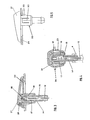
- Fig. 3 eine Sicht auf eine andere Ausführungsform einer Spritzdüse
- Fig. 4 einen Längsschnitt durch die in Fig. 3 wiedergegebene Spritzdüse
- Fig. 5 einen Schnitt nach V - V durch Fig. 4
- Fig. 1 is a schematic representation of a heated windscreen washer system
- Fig. 2 shows a section through a spray nozzle for the windshield washer shown in Fig. 1
- Fig. 3 is a view of another embodiment of a spray nozzle
- Fig. 4 shows a longitudinal section through the spray nozzle shown in Fig. 3
- 5 shows a section along V - V through FIG. 4
Die in der Zeichnung wiedergegebene Scheibenwaschanlage für Kraftfahrzeuge besteht aus einem Wasserbehälter 1, einer Wasserpumpe 2, einem sich zweifach bis zu jeweils einer Spritzdüse 6, 7 verzweigenden Schlauch 3, 4, 5 sowie einem Heizleiter 9, mit dessen Hilfe das in dem Behälter 1, dem Schlauch 3, 4, 5 und den Spritzdüsen 6, 7 stehende Wasser auf einer über dem Gefrierpunkt liegenden Temperatur gehalten wird. Der Heizleiter 9 ist in Form einer durchgehenden Schleife in dem das Waschwasser führenden Schlauch 3, 4, 5 verlegt, wobei an jedem der zu einer Spritzdüse 6, 7 führenden Abzweige 10, 11 eine Schlaufe 12 gebildet ist, die sich bis in das Innere der Spritzdüse 5, 7 erstreckt und dort zum Zwecke der Rückführung innerhalb des Schlauches umgelenkt ist. Im Falle der in Fig. 2 wiedergegebenen Ausführungsform ist in der Spritzdüse eine Haltenase 13 als Umführung für die Schlaufe 12 des Heizleiters vorgesehen.The windshield washer system for motor vehicles shown in the drawing consists of a
Im Falle der in den Fig. 3 bis 5 wiedergegebenen Ausführungsform ist das Rückschlagventil 19 in der Spritzdüse 5, 7 angeordnet. Sie weist einen gleichzeitig den Wasserführungskanal 15 bildenden Stecknippel 14 zum Einschieben in den das Waschwasser führenden Zuführungsschlauch 4, 5 auf und ist mit einem den Wasserzuführungskanal 15 umgebenden Ringraum 17 auf, der mit dem Wasserzuführungskanal 15 über seitliche Öffnungen 16 verbunden ist. Der Kanal 15 selbst ist an seinem Ende mittels eines Dichtstopfens 18 verschlossen, der auf seiner Außenfläche eine sich in Längsrichtung um den Stopfen erstreckende Nut aufweist, in die das Umlenkende der Schlaufe 12 des Heizleiters 10 eingelegt ist.In the case of the embodiment shown in FIGS. 3 to 5, the
Das Rückschlagventil 19 ist gebildet von einem Schlauchstück, das die seitlichen, den Wasserzuführungskanal 15 mit dem Ringraum 17 verbindenden Öffnungen 16 umschließt und an einem Ende, beispielsweise an dem den Dichtstopfen 18 umfasenden Rand fest verklebt ist, während sich das andere unverklebte Ende unter dem Wasserdruck aufweitet und einen Durchlass in den Raum 17 und von dort zur Düsenöffnung 25 freimacht.The
Die Spritzdüse ist - siehe insbesondere Fig. 3 - zweiteilig aus einem Sockelteil 20 und einer auf das Sockelteil aufclipsbaren Kappe 21 ausgebildet, wobei das Sockelteil 20 mit einem Flansch 22 und federnden Haltelaschen 23 versehen ist, mit deren Hilfe die Düse durch Klemmhalterung auf das Karosserieblech 24 des Fahrzeuges aufgebracht werden kann.The spray nozzle - see in particular Fig. 3 - is formed in two parts from a
Claims (6)
Applications Claiming Priority (2)
| Application Number | Priority Date | Filing Date | Title |
|---|---|---|---|
| DE4404409 | 1994-02-11 | ||
| DE19944404409 DE4404409A1 (en) | 1994-02-11 | 1994-02-11 | Windscreen washer system for motor vehicles |
Publications (1)
| Publication Number | Publication Date |
|---|---|
| EP0667267A1 true EP0667267A1 (en) | 1995-08-16 |
Family
ID=6510066
Family Applications (1)
| Application Number | Title | Priority Date | Filing Date |
|---|---|---|---|
| EP95101670A Withdrawn EP0667267A1 (en) | 1994-02-11 | 1995-02-08 | Window washing arrangement for vehicles |
Country Status (2)
| Country | Link |
|---|---|
| EP (1) | EP0667267A1 (en) |
| DE (1) | DE4404409A1 (en) |
Cited By (13)
| Publication number | Priority date | Publication date | Assignee | Title |
|---|---|---|---|---|
| EP0974503A2 (en) * | 1998-07-23 | 2000-01-26 | Mannesmann VDO Aktiengesellschaft | Windscreen cleaning apparatus |
| FR2783225A1 (en) * | 1998-09-10 | 2000-03-17 | Journee Paul Sa | Spray assembly for projecting washing liquid onto vehicle windscreen, comprises non return valve and heating wire passing through tube with free end located in spray chamber. |
| WO2000048878A1 (en) * | 1999-02-15 | 2000-08-24 | Robert Bosch Gmbh | Windscreen wiper |
| WO2000050277A1 (en) * | 1999-02-23 | 2000-08-31 | Robert Bosch Gmbh | Windshield wiper |
| ES2154190A1 (en) * | 1998-11-12 | 2001-03-16 | Domenech Jose Camino | Water heating device for de-icing the windshield of an automobile |
| WO2002034598A1 (en) * | 2000-10-28 | 2002-05-02 | Robert Bosch Gmbh | Nozzle device and method for operating a nozzle device |
| WO2004085218A1 (en) * | 2003-03-28 | 2004-10-07 | Valeo Systemes D'essuyage | Nozzle assembly for a windscreen washer system of a vehicle |
| DE102004018186A1 (en) * | 2004-04-14 | 2005-11-10 | Volkswagen Ag | Device for installing washing water line for motor vehicle windscreen washer system consists of profile body that accepts washing water line and at least one attachment device on supporting element of motor vehicle |
| DE102008003881A1 (en) * | 2008-01-10 | 2009-07-23 | Vola Plast Werner Hoppach Kg | Washer for windows and / or headlights of a vehicle |
| DE102008020227A1 (en) | 2008-04-22 | 2009-11-12 | Valeo Systèmes d'Essuyage | Wiper blade and windscreen wiper system with such a wiper blade |
| DE102008051584A1 (en) * | 2008-10-14 | 2010-04-15 | Valeo Systèmes d'Essuyage | Washer for vehicle windows and non-return valve for such a system |
| CN103909905B (en) * | 2008-03-26 | 2016-08-17 | 法雷奥系统公司 | Wiper for vehicle windscreen |
| US20200156597A1 (en) * | 2017-04-12 | 2020-05-21 | Continental Automotive Gmbh | Cleaning device for cleaning a transparent element of an optical or optoelectronic device |
Families Citing this family (4)
| Publication number | Priority date | Publication date | Assignee | Title |
|---|---|---|---|---|
| DE29703138U1 (en) * | 1997-02-24 | 1998-07-02 | Kroeger Hans Dipl Ing | Frost protection device |
| DE10037608B4 (en) * | 2000-08-02 | 2006-01-05 | Siemens Ag | Heatable cleaning device and method for heating such a cleaning device |
| DE102004022998B4 (en) * | 2004-05-10 | 2015-05-21 | Continental Automotive Gmbh | Windshield washing system |
| DE102015215932A1 (en) * | 2015-08-20 | 2017-02-23 | Robert Bosch Gmbh | Nozzle system for cleaning a pane |
Citations (3)
| Publication number | Priority date | Publication date | Assignee | Title |
|---|---|---|---|---|
| EP0240832A1 (en) * | 1986-03-21 | 1987-10-14 | Alligator Ventilfabrik GmbH | Electrical heating device for liquid in a windscreen wash system of a vehicle |
| EP0284669A1 (en) * | 1987-04-02 | 1988-10-05 | REHAU AG + Co | Coupling-piece for heatable flexible hoses |
| EP0456024A1 (en) * | 1990-05-02 | 1991-11-13 | REHAU AG + Co | Electrically heated hose |
Family Cites Families (1)
| Publication number | Priority date | Publication date | Assignee | Title |
|---|---|---|---|---|
| DE7431778U (en) * | 1975-04-17 | Wolf & Becker Gmbh & Co | Electric heating device for spray nozzles for vehicle windscreen washers |
-
1994
- 1994-02-11 DE DE19944404409 patent/DE4404409A1/en not_active Ceased
-
1995
- 1995-02-08 EP EP95101670A patent/EP0667267A1/en not_active Withdrawn
Patent Citations (3)
| Publication number | Priority date | Publication date | Assignee | Title |
|---|---|---|---|---|
| EP0240832A1 (en) * | 1986-03-21 | 1987-10-14 | Alligator Ventilfabrik GmbH | Electrical heating device for liquid in a windscreen wash system of a vehicle |
| EP0284669A1 (en) * | 1987-04-02 | 1988-10-05 | REHAU AG + Co | Coupling-piece for heatable flexible hoses |
| EP0456024A1 (en) * | 1990-05-02 | 1991-11-13 | REHAU AG + Co | Electrically heated hose |
Cited By (22)
| Publication number | Priority date | Publication date | Assignee | Title |
|---|---|---|---|---|
| US7269876B2 (en) * | 1998-07-23 | 2007-09-18 | Siemens Aktiengesellschaft | Window and lens glass cleaning system |
| EP0974503A3 (en) * | 1998-07-23 | 2001-09-19 | Mannesmann VDO Aktiengesellschaft | Windscreen cleaning apparatus |
| EP0974503A2 (en) * | 1998-07-23 | 2000-01-26 | Mannesmann VDO Aktiengesellschaft | Windscreen cleaning apparatus |
| US6393652B1 (en) | 1998-07-23 | 2002-05-28 | Mannesmann Vdo Ag | Window and lens glass cleaning system |
| FR2783225A1 (en) * | 1998-09-10 | 2000-03-17 | Journee Paul Sa | Spray assembly for projecting washing liquid onto vehicle windscreen, comprises non return valve and heating wire passing through tube with free end located in spray chamber. |
| WO2000015479A1 (en) * | 1998-09-10 | 2000-03-23 | Paul Journee S.A. | Improved spraying device for washing liquid and wiper bearing same |
| ES2154190A1 (en) * | 1998-11-12 | 2001-03-16 | Domenech Jose Camino | Water heating device for de-icing the windshield of an automobile |
| US6463621B1 (en) | 1999-02-15 | 2002-10-15 | Robert Bosch Gmbh | Windscreen wiper with spray nozzle |
| WO2000048878A1 (en) * | 1999-02-15 | 2000-08-24 | Robert Bosch Gmbh | Windscreen wiper |
| US6513185B1 (en) | 1999-02-23 | 2003-02-04 | Robert Bosch Gmbh | Windshield wiper |
| WO2000050277A1 (en) * | 1999-02-23 | 2000-08-31 | Robert Bosch Gmbh | Windshield wiper |
| WO2002034598A1 (en) * | 2000-10-28 | 2002-05-02 | Robert Bosch Gmbh | Nozzle device and method for operating a nozzle device |
| WO2004085218A1 (en) * | 2003-03-28 | 2004-10-07 | Valeo Systemes D'essuyage | Nozzle assembly for a windscreen washer system of a vehicle |
| DE102004018186A1 (en) * | 2004-04-14 | 2005-11-10 | Volkswagen Ag | Device for installing washing water line for motor vehicle windscreen washer system consists of profile body that accepts washing water line and at least one attachment device on supporting element of motor vehicle |
| DE102008003881A1 (en) * | 2008-01-10 | 2009-07-23 | Vola Plast Werner Hoppach Kg | Washer for windows and / or headlights of a vehicle |
| EP2078647A3 (en) * | 2008-01-10 | 2010-10-20 | Vola Plast Werner Hoppach KG | Washing assembly for screens and/or headlamps of a vehicle |
| US7878421B2 (en) | 2008-01-10 | 2011-02-01 | Vola Plast Werner Hoppach, KG | Wash system for window glasses and/or headlamps of a vehicle |
| CN103909905B (en) * | 2008-03-26 | 2016-08-17 | 法雷奥系统公司 | Wiper for vehicle windscreen |
| DE102008020227A1 (en) | 2008-04-22 | 2009-11-12 | Valeo Systèmes d'Essuyage | Wiper blade and windscreen wiper system with such a wiper blade |
| DE102008051584A1 (en) * | 2008-10-14 | 2010-04-15 | Valeo Systèmes d'Essuyage | Washer for vehicle windows and non-return valve for such a system |
| WO2010043383A1 (en) * | 2008-10-14 | 2010-04-22 | Valeo Systemes D'essuyage | Washing system for vehicle windows and check valve for such a system |
| US20200156597A1 (en) * | 2017-04-12 | 2020-05-21 | Continental Automotive Gmbh | Cleaning device for cleaning a transparent element of an optical or optoelectronic device |
Also Published As
| Publication number | Publication date |
|---|---|
| DE4404409A1 (en) | 1995-08-17 |
Similar Documents
| Publication | Publication Date | Title |
|---|---|---|
| EP0667267A1 (en) | Window washing arrangement for vehicles | |
| DE102007062304B4 (en) | Adapter for a wiper blade for cleaning vehicle windows | |
| DE19926861B4 (en) | Method and device for producing an elongated closed channel within a body cavity | |
| EP2265477B1 (en) | Wiper blade and windshield wiper system having such a wiper blade | |
| DE19841021A1 (en) | Liquid tank and fuel tank arrangement | |
| DE102008049270A1 (en) | Wiper arm / wiper blade connection, wiper blade and windscreen wiper system | |
| DE3907968A1 (en) | WINDOW CLEANING SYSTEM | |
| DE102007062254A1 (en) | Supporting an entry panel on a support element of a motor vehicle | |
| DE102019203715A1 (en) | Windshield wiper arrangement with an adapter unit for establishing fluid-conducting and electrical connections | |
| DE19902431B4 (en) | Intermediate piece with a connection of washing liquid lines of a window cleaning system | |
| EP2414646A1 (en) | Injection apparatus for urea aqueous solution | |
| DE4303113C2 (en) | Spray nozzle device for a windscreen washer system | |
| WO2001021442A1 (en) | Device for fixing a functional element to a motor vehicle body | |
| DE20318863U1 (en) | Holding and connecting device | |
| DE10322769A1 (en) | Device for feeding fuel to internal combustion engine fuel injection valves has strip-shaped fixing element to which valve cups are additionally attached arranged on outside of fuel distribution line at least near valve cups | |
| DE10151385A1 (en) | Modular device for cleaning the windshield of a motor vehicle | |
| DE19517055B4 (en) | Spraying device for dispensing washing liquid onto a pane of a vehicle to be cleaned | |
| DE102009057022B4 (en) | Device for guiding cleaning fluid | |
| DE102019128524A1 (en) | Motor vehicle with a water tank arranged in the area in front of the windshield | |
| DE10242034B4 (en) | Subunit for a windscreen washer system | |
| EP1040973A2 (en) | Electrically heated hose for windscreen cleaning device | |
| DE202013003759U1 (en) | turbocharger | |
| DE10010743B4 (en) | Engine compartment seal for cars | |
| EP0992420A2 (en) | Motorcar with preassembled mounting unit | |
| DE10212413A1 (en) | Washing water tube for motor vehicle windscreen washer system, has heating wire whose end regions extend between sealing ring and connecting piece at one end of tube |
Legal Events
| Date | Code | Title | Description |
|---|---|---|---|
| PUAI | Public reference made under article 153(3) epc to a published international application that has entered the european phase |
Free format text: ORIGINAL CODE: 0009012 |
|
| AK | Designated contracting states |
Kind code of ref document: A1 Designated state(s): DE ES FR GB SE |
|
| 17P | Request for examination filed |
Effective date: 19951130 |
|
| 17Q | First examination report despatched |
Effective date: 19960923 |
|
| GRAG | Despatch of communication of intention to grant |
Free format text: ORIGINAL CODE: EPIDOS AGRA |
|
| GRAG | Despatch of communication of intention to grant |
Free format text: ORIGINAL CODE: EPIDOS AGRA |
|
| GRAH | Despatch of communication of intention to grant a patent |
Free format text: ORIGINAL CODE: EPIDOS IGRA |
|
| GRAH | Despatch of communication of intention to grant a patent |
Free format text: ORIGINAL CODE: EPIDOS IGRA |
|
| RAP1 | Party data changed (applicant data changed or rights of an application transferred) |
Owner name: MANNESMANN VDO AKTIENGESELLSCHAFT |
|
| STAA | Information on the status of an ep patent application or granted ep patent |
Free format text: STATUS: THE APPLICATION IS DEEMED TO BE WITHDRAWN |
|
| 18D | Application deemed to be withdrawn |
Effective date: 19980901 |