EP0665479A1 - Zusammengesetzter Sicherheitsschalter - Google Patents
Zusammengesetzter Sicherheitsschalter Download PDFInfo
- Publication number
- EP0665479A1 EP0665479A1 EP95410005A EP95410005A EP0665479A1 EP 0665479 A1 EP0665479 A1 EP 0665479A1 EP 95410005 A EP95410005 A EP 95410005A EP 95410005 A EP95410005 A EP 95410005A EP 0665479 A1 EP0665479 A1 EP 0665479A1
- Authority
- EP
- European Patent Office
- Prior art keywords
- switch
- switches
- composite
- voltage
- closed
- Prior art date
- Legal status (The legal status is an assumption and is not a legal conclusion. Google has not performed a legal analysis and makes no representation as to the accuracy of the status listed.)
- Granted
Links
Images


Classifications
-
- G—PHYSICS
- G05—CONTROLLING; REGULATING
- G05B—CONTROL OR REGULATING SYSTEMS IN GENERAL; FUNCTIONAL ELEMENTS OF SUCH SYSTEMS; MONITORING OR TESTING ARRANGEMENTS FOR SUCH SYSTEMS OR ELEMENTS
- G05B9/00—Safety arrangements
- G05B9/02—Safety arrangements electric
- G05B9/03—Safety arrangements electric with multiple-channel loop, i.e. redundant control systems
-
- H—ELECTRICITY
- H01—ELECTRIC ELEMENTS
- H01H—ELECTRIC SWITCHES; RELAYS; SELECTORS; EMERGENCY PROTECTIVE DEVICES
- H01H9/00—Details of switching devices, not covered by groups H01H1/00 - H01H7/00
- H01H2009/0083—Details of switching devices, not covered by groups H01H1/00 - H01H7/00 using redundant components, e.g. two pressure tubes for pressure switch
Definitions
- the present invention relates to a safety switch, i.e. a switch intended to ensure the most reliable switching possible of a load in an environment where, for safety reasons, it is extremely important that this load is powered or not when the switch is operated.
- An example of such an environment is an aircraft, where it is essential that elements are actuated as soon as the pilot or a computer acts on corresponding switches.
- the failure of a switch for example a lack of switching when it is actuated, or inadvertent switching, can have serious consequences.
- An object of the present invention is to provide a particularly reliable safety switch requiring low maintenance.
- Each simple switch is provided with a current measurement element in the simple switch in the case of a parallel association, with a voltage measurement element at the terminals of the simple switch in the case of a association in series, and a control circuit receiving the information provided by the measuring elements as well as a control signal from the simple switch, and providing an active fault signal if the measured voltage is high or the current measured low while the simple switch is commanded to be closed, or if the measured current is high or the measured voltage low while the simple switch is commanded to be open.
- simple switches arranged in series are each provided with a resistor connected in parallel of high value.
- the fault signal is active only if the measured voltage is high while the single switch is commanded to be closed or else if the measured current is high while the simple switch is commanded to be open.
- the present invention also provides a method for testing a composite switch of the aforementioned type, comprising the steps of switching simple switches of the composite switch without the conduction state of the composite switch being modified, and of noting the control circuit failure signals.
- FIG. 1A represents a type A of composite switch intended to ensure high reliability upon closing. Such a switch is suitable for controlling a load which it is important to supply and which one can afford to leave supplied in the event of failure of the composite switch.
- This composite switch A comprises two simple switches S1 and S2 connected in parallel. Initially, the switches S1 and S2 are open. When one wants to supply the load, one of the switches, for example S1, is closed. If the faulty switch S1 can no longer close, the load is supplied by closing the switch S2. he is also it is possible to close the two switches S1 and S2 when supplying the load. In this case, if one of the switches fails to close, the other switch still ensures closing.
- FIG. 1B represents a type B of composite switch with requirement on opening. This type of switch is used when it is important that the load is switched off when you act on the switch, but that you tolerate an untimely extinction of the latter.
- This composite switch comprises two simple switches S1 and S2 connected in series.
- the two switches S1 and S2 are closed, and the load is supplied.
- one of the switches for example S1 is open. If the faulty switch S1 remains closed, the switch S2 is opened. To switch off the load, the two switches S1 and S2 could also be opened. So, if one of the switches remains closed in the event of a fault, the load is still switched off by the other switch.
- FIG. 1C represents a type C of a composite switch with closing and opening requirements, the priority in opening being greater than the priority in closing. This type of switch is used when it is essential that the load is supplied or switched off when the switch is operated.
- This composite switch C comprises two composite switches of type B, S1 / S2 and S3 / S4, connected in parallel. So that this composite switch no longer performs its function, at least two of its single switches must fail in a predetermined manner.
- the possibilities of breakdown are as follows: the composite switch remains closed if the switches S1 and S2 are closed or if the switches S3 and S4 are closed; and the composite switch remains open for one of the pairs of open switches S1 / S3, S2 / S4, S2 / S3, and S1 / S4.
- FIG. 1D represents a type C ′ of composite switch with requirement for opening and closing, the priority for closing being higher than that for opening.
- This switch includes two type A composite switches, S1 / S3 and S2 / S4, connected in series.
- the failure of this composite switch is as follows: the composite switch remains closed if the pairs of switches S1 / S2, S1 / S4, S3 / S2 and S3 / S4 are closed; and the composite switch remains open if the switches S1 and S3 are open or if the switches S2 and S4 are open.
- FIG. 2A represents an embodiment of a simple switch according to the invention, to be integrated into a composite switch, allowing fault detection and reporting this fault so that an observer can replace this simple switch.
- Each single switch S of a composite switch according to the invention comprises an element I for measuring the current passing through the switch S and an element U for measuring the voltage across the terminals of the assembly of the switch S and of the element I.
- the voltage measurement could also be done directly at the terminals of the switch S.
- the configuration shown makes it possible, for a voltage measurement, to check the switch S and the current measurement element at the same time I.
- the measured voltage and current are supplied to a control circuit 10 which supplies an error signal ERR when a failure of the switch S is detected.
- This ERR signal is, for example, used by a computer which controls the switches, to gather all the fault information. switches and report them to the observer.
- the control circuit 10 also takes into account a signal CS for controlling the switch S, which is for example a signal supplied by a computer.
- the switch S When the switch S is closed, the voltage measured by the element U is practically zero and the current measured by the element I is non-zero if a load is connected to the switch. If the switch S is open, the voltage measured by the element U is high, that is to say close to the supply voltage of the load, and the current measured by the element I is zero.
- the control circuit 10 signals an opening failure of the switch S if the measured voltage is high while the signal CS is in a state selecting the closing of the switch S. An opening failure could also be reported if the current measured was zero, but this measurement would trigger an untimely failure signaling if a load was not connected, or arranged in series with another open switch.
- Double measurement is in any case necessary as soon as at least two switches S are combined in one of the composite types A, B, C or C ', as described below.
- FIG. 2B represents two switches S1 and S2 according to the invention combined in a composite switch of type A.
- the current measurements in the switches S1 and S2 are made for example by measuring the voltages at the terminals of respective shunt resistors R1 and R2 arranged in series with switches S1 and S2.
- the control circuit 10 essentially uses current measurements to detect a frank failure. If the two switches S1 and S2 are closed, a substantially equal current flows through the resistors R1 and R2, assumed to have the same value. If one of the switches S1 and S2 is closed, it is useless, except to check the evolution of the resistance of the closed switch, to measure the voltage across the terminals of the other switch, since this is practically the even if this switch is open or closed. If one of the switches is closed normally and the other is closed unexpectedly, a non-zero current is measured in the latter, which triggers the detection of its failure by the control circuit 10. Similarly, in the case where it is certain that a load is connected, if one of the switches is inadvertently opened, the measured current becomes zero, which also triggers a fault detection.
- FIG. 2C represents a type B composite switch in which the voltage measurements at the terminals of the switches are used instead to detect a frank failure.
- Each of the switches S1 and S2 comprises, in addition to the corresponding voltage measurement element U, a respective resistor R1 'and R2' connected to its terminals.
- the values of the resistors R1 'and R2' are sufficiently high so that the load which the composite switch controls is not disturbed when one of the switches S1 and S2 is open.
- the voltage across each of the resistors R1 'and R2' is equal to half of the supply voltage, assuming that the resistors R1 'and R2' have the same value.
- the voltage across its terminals is canceled and its failure is detected.
- the voltage across its terminals becomes high, which also triggers the detection of its failure.
- the switches of the closed branch can be verified individually statically by measuring the voltage. To guarantee the accuracy of this verification, the branch supposed to be open is previously verified by the current measurement. The switches of the open branch cannot be checked individually statically.
- the switches S of the second couple can be verified individually statically by the current measurement.
- the first torque is checked beforehand by measuring the voltage of one of the switches S of this torque. The first torque switches cannot be checked statically individually.
- FIGS. 3A to 3D are considered to be an integral part of the present description. They represent tables respectively illustrating the different states of the composite switches A to C 'as a function of all the combinations of states of the simple switches S forming the composite switches.
- FIGS. 4A to 4D represent transition diagrams of the composite switches A to C '.
- the left column we represent the configurations where the composite switches are open and in the right column the configurations where they are closed. These configurations are represented by their numbers in the first columns of the tables in FIGS. 3A to 3D.
- One configuration is connected to another by a line when it suffices to switch a single simple switch to switch from one to the other of these connected configurations.
- This kind of representation is useful for controlling a composite switch so that you can test its simple switches individually on opening and closing, as described below.
- the present invention makes it possible to carry out complete test cycles without disturbing the commanded load, that is to say that it is possible to check some of the simple switches S (or all) on opening and closing without causing provided that a load is powered off or that a powered load is switched off.
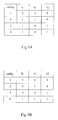
- FIG. 5 represents in table form examples of complete test cycles which can be carried out in each of the composite switches A to C ′.
- In the left column we show examples of test cycles performed while the composite switch remains open, and in the right column, we show examples of test cycles performed while the composite switch remains closed.
- Different configurations represented by the numbers of the corresponding tables, are linked by arrows indicating the direction of switching from one configuration to another.
- the composite switch A it is not possible to fully test all the switches S without supplying the load. However, they can be tested completely while the load is continuously supplied. In this case, the composite switch is tested by performing cycle 2, 4, 3, 4 (these numbers corresponding to the configurations in the table in FIG. 3A).
- cycle 1, 2, 1, 3 is carried out (these numbers corresponding to the configurations in the table in FIG. 3B).
- the present invention has been described using four types of composite switch. Of course, the present invention applies to other composite switches comprising more than four simple switches.
Landscapes
- Physics & Mathematics (AREA)
- General Physics & Mathematics (AREA)
- Engineering & Computer Science (AREA)
- Automation & Control Theory (AREA)
- Keying Circuit Devices (AREA)
- Electronic Switches (AREA)
Applications Claiming Priority (2)
| Application Number | Priority Date | Filing Date | Title |
|---|---|---|---|
| FR9401305A FR2715738B1 (fr) | 1994-01-31 | 1994-01-31 | Interrupteur composite de sécurité. |
| FR9401305 | 1994-01-31 |
Publications (2)
| Publication Number | Publication Date |
|---|---|
| EP0665479A1 true EP0665479A1 (de) | 1995-08-02 |
| EP0665479B1 EP0665479B1 (de) | 2000-08-02 |
Family
ID=9459812
Family Applications (1)
| Application Number | Title | Priority Date | Filing Date |
|---|---|---|---|
| EP95410005A Expired - Lifetime EP0665479B1 (de) | 1994-01-31 | 1995-01-26 | Zusammengesetzter Sicherheitsschalter |
Country Status (4)
| Country | Link |
|---|---|
| US (1) | US5559438A (de) |
| EP (1) | EP0665479B1 (de) |
| DE (1) | DE69518173T2 (de) |
| FR (1) | FR2715738B1 (de) |
Cited By (4)
| Publication number | Priority date | Publication date | Assignee | Title |
|---|---|---|---|---|
| EP0865055A1 (de) * | 1996-09-03 | 1998-09-16 | The Nippon Signal Co. Ltd. | Treiberschaltung fur last |
| EP1594021A1 (de) * | 2004-05-05 | 2005-11-09 | Siemens Aktiengesellschaft | Schaltungsanordnung sowie Verfahren zum Testen von Relaisschaltkontakten einer digitalen Ausgangsschaltung |
| EP2045683A1 (de) | 2007-10-05 | 2009-04-08 | Phoenix Contact GmbH & Co. KG | Vorrichtung und Verfahren zur Überprüfung von im Lastkreis einer sicherheitstechnischen Ausgangsschaltung redundant angeschalteten Aktoren |
| CN103733147A (zh) * | 2011-08-18 | 2014-04-16 | 西门子公司 | 在功率开关构成的设备中进行开关的方法以及由多个功率开关构成的设备 |
Families Citing this family (15)
| Publication number | Priority date | Publication date | Assignee | Title |
|---|---|---|---|---|
| EP0752593A3 (de) * | 1995-07-07 | 1998-01-07 | Siemens Aktiengesellschaft | Verfahren zur Früherkennung von Ausfällen bei Leistungshalbleitermodulen |
| GB9819911D0 (en) * | 1998-09-11 | 1998-11-04 | Meggitt Mobrey Limited | Switch control apparatus and method |
| US6493204B1 (en) | 1999-07-09 | 2002-12-10 | Kelsey-Hayes Company | Modulated voltage for a solenoid valve |
| DE10011410A1 (de) * | 2000-03-09 | 2001-09-20 | Bosch Gmbh Robert | Vorrichtung zur sicheren Signalerzeugung |
| US6882155B2 (en) * | 2001-04-19 | 2005-04-19 | Vince J Lazzaro | Remotely actuated, circuit testing emergency stop apparatus and method |
| US7177383B2 (en) * | 2004-02-02 | 2007-02-13 | James Hardy | Method and system for safety regulation in nuclear power regulating systems |
| US7417519B2 (en) * | 2004-09-30 | 2008-08-26 | Rockwell Automation Technologies, Inc. | Emergency stop relay combination |
| DE102004058540A1 (de) * | 2004-12-04 | 2006-06-08 | Bosch Rexroth Ag | Verfahren und Vorrichtung zur Überwachung einer Spannung |
| DE102008044651A1 (de) * | 2008-08-27 | 2010-03-04 | Robert Bosch Gmbh | Spannungsüberwachungsanordnung für ein Sicherheitsmodul |
| DE102010041998A1 (de) * | 2010-10-05 | 2012-04-05 | Robert Bosch Gmbh | Verfahren zur Vorhersage der Einsatzfähigkeit eines Relais oder eines Schützes |
| EP2595019B1 (de) * | 2011-11-17 | 2019-03-13 | Rockwell Automation Limited | Verfahren und Vorrichtung zur Steuerung von analogem Ausgangsstrom |
| DE102012002847B4 (de) * | 2012-02-13 | 2016-11-17 | Weinert Engineering GmbH | Anordnung zum Schalten einer Infusionspumpe und Verfahren zu deren Inbetriebnahme |
| CN103754358B (zh) * | 2014-01-10 | 2016-01-27 | 深圳市大疆创新科技有限公司 | 一种无人飞行器的起落架控制方法及装置 |
| DE202016006083U1 (de) * | 2016-09-30 | 2018-01-03 | WAGO Verwaltungsgesellschaft mit beschränkter Haftung | Parallel geschaltete Halbleiterschalter zur redundanten Stromversorgung und Unterbrechung |
| CN109823522B (zh) * | 2017-11-23 | 2024-02-23 | 成都凯天电子股份有限公司 | 多冗余度起落架电动收放控制器 |
Citations (5)
| Publication number | Priority date | Publication date | Assignee | Title |
|---|---|---|---|---|
| EP0192027A1 (de) * | 1985-01-23 | 1986-08-27 | Westinghouse Electric Corporation | Prüfbarer fehlertoleranter Schnittstellenschaltkreis zur Steuerung von Anlagenprozesseinrichtungen |
| EP0221775A1 (de) * | 1985-10-31 | 1987-05-13 | Westinghouse Electric Corporation | Prüfbare Auswahllogik-Leistungsschaltung und Verfahren zu deren Prüfung |
| EP0223461A1 (de) * | 1985-10-31 | 1987-05-27 | Westinghouse Electric Corporation | Prüfbare Auswahllogik-Leistungsschnittstelle |
| DE3732079A1 (de) * | 1987-09-24 | 1989-04-06 | Vdo Schindling | Verfahren und vorrichtung zum betrieb eines ueberbrueckungsstromkreises fuer mindestens einen mechanischen schaltkontakt innerhalb einer eine sicherheitsfunktion ausuebenden schaltungsanordnung |
| US4980573A (en) * | 1989-10-02 | 1990-12-25 | Automotive Systems Laboratory, Inc. | Firing circuit with three crash sensors |
Family Cites Families (5)
| Publication number | Priority date | Publication date | Assignee | Title |
|---|---|---|---|---|
| US4687623A (en) * | 1985-10-31 | 1987-08-18 | Westinghouse Electric Corp. | Self-compensating voted logic power interface with tester |
| US4696785A (en) * | 1985-10-31 | 1987-09-29 | Westinghouse Electric Corp. | Testable voted logic power circuit and method of testing the same |
| US4843537A (en) * | 1986-07-04 | 1989-06-27 | Hitachi, Ltd. | Control system |
| US5006301A (en) * | 1989-03-22 | 1991-04-09 | Joyner Engineers And Trainers, Inc. | Method and apparatus for control rod drop monitoring |
| GB9006091D0 (en) * | 1990-03-17 | 1990-05-16 | Eaton Corp | Transducer fault test logic |
-
1994
- 1994-01-31 FR FR9401305A patent/FR2715738B1/fr not_active Expired - Fee Related
-
1995
- 1995-01-25 US US08/377,733 patent/US5559438A/en not_active Expired - Fee Related
- 1995-01-26 EP EP95410005A patent/EP0665479B1/de not_active Expired - Lifetime
- 1995-01-26 DE DE69518173T patent/DE69518173T2/de not_active Expired - Fee Related
Patent Citations (5)
| Publication number | Priority date | Publication date | Assignee | Title |
|---|---|---|---|---|
| EP0192027A1 (de) * | 1985-01-23 | 1986-08-27 | Westinghouse Electric Corporation | Prüfbarer fehlertoleranter Schnittstellenschaltkreis zur Steuerung von Anlagenprozesseinrichtungen |
| EP0221775A1 (de) * | 1985-10-31 | 1987-05-13 | Westinghouse Electric Corporation | Prüfbare Auswahllogik-Leistungsschaltung und Verfahren zu deren Prüfung |
| EP0223461A1 (de) * | 1985-10-31 | 1987-05-27 | Westinghouse Electric Corporation | Prüfbare Auswahllogik-Leistungsschnittstelle |
| DE3732079A1 (de) * | 1987-09-24 | 1989-04-06 | Vdo Schindling | Verfahren und vorrichtung zum betrieb eines ueberbrueckungsstromkreises fuer mindestens einen mechanischen schaltkontakt innerhalb einer eine sicherheitsfunktion ausuebenden schaltungsanordnung |
| US4980573A (en) * | 1989-10-02 | 1990-12-25 | Automotive Systems Laboratory, Inc. | Firing circuit with three crash sensors |
Cited By (6)
| Publication number | Priority date | Publication date | Assignee | Title |
|---|---|---|---|---|
| EP0865055A1 (de) * | 1996-09-03 | 1998-09-16 | The Nippon Signal Co. Ltd. | Treiberschaltung fur last |
| EP0865055A4 (de) * | 1996-09-03 | 2006-03-22 | Nippon Signal Co Ltd | Treiberschaltung fur last |
| EP1594021A1 (de) * | 2004-05-05 | 2005-11-09 | Siemens Aktiengesellschaft | Schaltungsanordnung sowie Verfahren zum Testen von Relaisschaltkontakten einer digitalen Ausgangsschaltung |
| EP2045683A1 (de) | 2007-10-05 | 2009-04-08 | Phoenix Contact GmbH & Co. KG | Vorrichtung und Verfahren zur Überprüfung von im Lastkreis einer sicherheitstechnischen Ausgangsschaltung redundant angeschalteten Aktoren |
| US8138765B2 (en) | 2007-10-05 | 2012-03-20 | Phoenix Contact Gmbh & Co. Kg | Device and method for actuator monitoring of a safety-related load circuit connected with two channels |
| CN103733147A (zh) * | 2011-08-18 | 2014-04-16 | 西门子公司 | 在功率开关构成的设备中进行开关的方法以及由多个功率开关构成的设备 |
Also Published As
| Publication number | Publication date |
|---|---|
| DE69518173T2 (de) | 2001-03-15 |
| FR2715738A1 (fr) | 1995-08-04 |
| FR2715738B1 (fr) | 1996-04-12 |
| EP0665479B1 (de) | 2000-08-02 |
| DE69518173D1 (de) | 2000-09-07 |
| US5559438A (en) | 1996-09-24 |
Similar Documents
| Publication | Publication Date | Title |
|---|---|---|
| EP0665479B1 (de) | Zusammengesetzter Sicherheitsschalter | |
| EP2063278B1 (de) | Verfahren zur Prüfung der digitalen Ausgängein eines PLC-moduls und entsprechendes PLC-modul | |
| EP2517347B1 (de) | Neukonfigurierbarer wandler mit fehlertoleranz für den betrieb eines synchronen mehrphasenmotors mit permanentmagneten und anordnung mit diesem wandler und motor | |
| KR900004559A (ko) | 차량승객 안정장치의 점화회로 | |
| EP0048192B1 (de) | Anordnung zum automatischen Prüfen einer Vielzahl von Anzeigelampen | |
| CA2315896C (fr) | Circuit electronique de surveillance de tension electrique | |
| CA1171500A (fr) | Commande electronique pour transmission automatique de vehicule automobile utilisant un microcalculateur | |
| CA1296059C (fr) | Dispositif pour detecter les coupures et les court-circuits dansau moins une portion de circuit electrique | |
| EP1022570A2 (de) | Ausfallsicheres Überwachungssystem für ein Potentiometer | |
| FR2735882A1 (fr) | Systeme et procede de verification d'un systeme de commande numerique | |
| EP3938792B1 (de) | Elektrische anlage mit einem überwachungsmodul | |
| EP0115994A1 (de) | Anpassteil zur Verbindung eines Rechners mit einem Betätigungsteil | |
| EP2317527A1 (de) | System zur präventiven Diagnose eines Kontaktscheinwiderstands und von Überlastungen eines Umschalters | |
| FR2883380A1 (fr) | Dispositif de mesure de courant perfectionne, notamment de courant de batterie | |
| FR2631453A1 (fr) | Dispositif testeur de fusible pour appareil de mesure d'intensite de courant | |
| FR2655155A1 (fr) | Dispisitif electrique de mesure a distance d'une consommation d'energie, en particulier d'une consommation de gaz. | |
| FR2831979A1 (fr) | Dispositif d'information lumineuse concernant l'etat de fonctionnement d'un systeme et procede de gestion d'un tel dispositif, notamment dans le domaine avionique | |
| EP3938793B1 (de) | Elektrische anlage mit einem überwachungsmodul | |
| OA10526A (fr) | Cellule pour entrées continues destinée à des circuits d'acquisition d'informations | |
| FR2696240A1 (fr) | Système de commutation autotestable. | |
| FR2831980A1 (fr) | Procede de gestion d'un dispositif d'information lumineuse et dispositif mettant en oeuvre ce procede, notamment dans le domaine avionique | |
| EP0167445B1 (de) | Anzeigevorrichtung mit, von einer Diodenmatrix, einzeln elektrisch steuerbaren Elementen | |
| FR2491661A1 (fr) | Dispositif, tel que balance, comportant l'affichage numerique de donnees | |
| FR2650451A1 (fr) | Circuit d'entree, du type tout ou rien, d'un dispositif d'automatisme | |
| EP0033785A1 (de) | Sicherheitskontrollsystem für industriellen Prozess |
Legal Events
| Date | Code | Title | Description |
|---|---|---|---|
| PUAI | Public reference made under article 153(3) epc to a published international application that has entered the european phase |
Free format text: ORIGINAL CODE: 0009012 |
|
| AK | Designated contracting states |
Kind code of ref document: A1 Designated state(s): CH DE FR GB IT LI NL |
|
| 17P | Request for examination filed |
Effective date: 19960112 |
|
| 17Q | First examination report despatched |
Effective date: 19981027 |
|
| GRAG | Despatch of communication of intention to grant |
Free format text: ORIGINAL CODE: EPIDOS AGRA |
|
| GRAG | Despatch of communication of intention to grant |
Free format text: ORIGINAL CODE: EPIDOS AGRA |
|
| GRAH | Despatch of communication of intention to grant a patent |
Free format text: ORIGINAL CODE: EPIDOS IGRA |
|
| GRAH | Despatch of communication of intention to grant a patent |
Free format text: ORIGINAL CODE: EPIDOS IGRA |
|
| GRAA | (expected) grant |
Free format text: ORIGINAL CODE: 0009210 |
|
| AK | Designated contracting states |
Kind code of ref document: B1 Designated state(s): CH DE FR GB IT LI NL |
|
| PG25 | Lapsed in a contracting state [announced via postgrant information from national office to epo] |
Ref country code: NL Free format text: LAPSE BECAUSE OF FAILURE TO SUBMIT A TRANSLATION OF THE DESCRIPTION OR TO PAY THE FEE WITHIN THE PRESCRIBED TIME-LIMIT Effective date: 20000802 Ref country code: IT Free format text: LAPSE BECAUSE OF FAILURE TO SUBMIT A TRANSLATION OF THE DESCRIPTION OR TO PAY THE FEE WITHIN THE PRE;WARNING: LAPSES OF ITALIAN PATENTS WITH EFFECTIVE DATE BEFORE 2007 MAY HAVE OCCURRED AT ANY TIME BEFORE 2007. THE CORRECT EFFECTIVE DATE MAY BE DIFFERENT FROM THE ONE RECORDED.SCRIBED TIME-LIMIT Effective date: 20000802 Ref country code: GB Free format text: LAPSE BECAUSE OF FAILURE TO SUBMIT A TRANSLATION OF THE DESCRIPTION OR TO PAY THE FEE WITHIN THE PRESCRIBED TIME-LIMIT Effective date: 20000802 |
|
| REG | Reference to a national code |
Ref country code: CH Ref legal event code: EP |
|
| REF | Corresponds to: |
Ref document number: 69518173 Country of ref document: DE Date of ref document: 20000907 |
|
| NLV1 | Nl: lapsed or annulled due to failure to fulfill the requirements of art. 29p and 29m of the patents act | ||
| GBV | Gb: ep patent (uk) treated as always having been void in accordance with gb section 77(7)/1977 [no translation filed] |
Effective date: 20000802 |
|
| PG25 | Lapsed in a contracting state [announced via postgrant information from national office to epo] |
Ref country code: LI Free format text: LAPSE BECAUSE OF NON-PAYMENT OF DUE FEES Effective date: 20010131 Ref country code: CH Free format text: LAPSE BECAUSE OF NON-PAYMENT OF DUE FEES Effective date: 20010131 |
|
| PLBE | No opposition filed within time limit |
Free format text: ORIGINAL CODE: 0009261 |
|
| STAA | Information on the status of an ep patent application or granted ep patent |
Free format text: STATUS: NO OPPOSITION FILED WITHIN TIME LIMIT |
|
| 26N | No opposition filed | ||
| REG | Reference to a national code |
Ref country code: CH Ref legal event code: PL |
|
| PG25 | Lapsed in a contracting state [announced via postgrant information from national office to epo] |
Ref country code: FR Free format text: LAPSE BECAUSE OF NON-PAYMENT OF DUE FEES Effective date: 20010928 |
|
| PG25 | Lapsed in a contracting state [announced via postgrant information from national office to epo] |
Ref country code: DE Free format text: LAPSE BECAUSE OF NON-PAYMENT OF DUE FEES Effective date: 20011101 |
|
| REG | Reference to a national code |
Ref country code: FR Ref legal event code: ST |