EP0664102B1 - Vorrichtung zur Steuerung der Medikamenten-Abgabe und zur Bestimmung der Pulssignale - Google Patents
Vorrichtung zur Steuerung der Medikamenten-Abgabe und zur Bestimmung der Pulssignale Download PDFInfo
- Publication number
- EP0664102B1 EP0664102B1 EP94308782A EP94308782A EP0664102B1 EP 0664102 B1 EP0664102 B1 EP 0664102B1 EP 94308782 A EP94308782 A EP 94308782A EP 94308782 A EP94308782 A EP 94308782A EP 0664102 B1 EP0664102 B1 EP 0664102B1
- Authority
- EP
- European Patent Office
- Prior art keywords
- pulse wave
- medication delivery
- medication
- pulse
- waveform
- Prior art date
- Legal status (The legal status is an assumption and is not a legal conclusion. Google has not performed a legal analysis and makes no representation as to the accuracy of the status listed.)
- Expired - Lifetime
Links
- 229940079593 drug Drugs 0.000 title claims description 220
- 239000003814 drug Substances 0.000 title claims description 220
- 238000001514 detection method Methods 0.000 title claims description 58
- 230000015654 memory Effects 0.000 claims description 89
- 238000001228 spectrum Methods 0.000 claims description 82
- 238000004458 analytical method Methods 0.000 claims description 53
- 230000036772 blood pressure Effects 0.000 claims description 27
- 230000033228 biological regulation Effects 0.000 claims description 24
- 238000004364 calculation method Methods 0.000 claims description 7
- 238000004891 communication Methods 0.000 claims description 2
- 238000000034 method Methods 0.000 description 28
- 238000010586 diagram Methods 0.000 description 25
- 230000009471 action Effects 0.000 description 21
- 239000002160 alpha blocker Substances 0.000 description 18
- 230000004913 activation Effects 0.000 description 17
- 239000002876 beta blocker Substances 0.000 description 16
- 229940097320 beta blocking agent Drugs 0.000 description 16
- 239000000203 mixture Substances 0.000 description 14
- 230000008929 regeneration Effects 0.000 description 13
- 238000011069 regeneration method Methods 0.000 description 13
- 101150022075 ADR1 gene Proteins 0.000 description 10
- 101100422887 Saccharomyces cerevisiae (strain ATCC 204508 / S288c) SWI1 gene Proteins 0.000 description 10
- 238000005259 measurement Methods 0.000 description 10
- 210000004204 blood vessel Anatomy 0.000 description 9
- 230000008859 change Effects 0.000 description 9
- 238000005070 sampling Methods 0.000 description 9
- 101100490566 Arabidopsis thaliana ADR2 gene Proteins 0.000 description 8
- 101100269260 Saccharomyces cerevisiae (strain ATCC 204508 / S288c) ADH2 gene Proteins 0.000 description 8
- AQHHHDLHHXJYJD-UHFFFAOYSA-N propranolol Chemical compound C1=CC=C2C(OCC(O)CNC(C)C)=CC=CC2=C1 AQHHHDLHHXJYJD-UHFFFAOYSA-N 0.000 description 8
- 210000001367 artery Anatomy 0.000 description 6
- 102000012740 beta Adrenergic Receptors Human genes 0.000 description 6
- 108010079452 beta Adrenergic Receptors Proteins 0.000 description 6
- 230000005281 excited state Effects 0.000 description 6
- 239000008280 blood Substances 0.000 description 5
- 210000004369 blood Anatomy 0.000 description 5
- 238000009795 derivation Methods 0.000 description 5
- 210000002321 radial artery Anatomy 0.000 description 5
- 239000012530 fluid Substances 0.000 description 4
- HYIMSNHJOBLJNT-UHFFFAOYSA-N nifedipine Chemical compound COC(=O)C1=C(C)NC(C)=C(C(=O)OC)C1C1=CC=CC=C1[N+]([O-])=O HYIMSNHJOBLJNT-UHFFFAOYSA-N 0.000 description 4
- 229960001597 nifedipine Drugs 0.000 description 4
- 230000001360 synchronised effect Effects 0.000 description 4
- 239000003795 chemical substances by application Substances 0.000 description 3
- 238000002474 experimental method Methods 0.000 description 3
- MRBDMNSDAVCSSF-UHFFFAOYSA-N phentolamine Chemical compound C1=CC(C)=CC=C1N(C=1C=C(O)C=CC=1)CC1=NCCN1 MRBDMNSDAVCSSF-UHFFFAOYSA-N 0.000 description 3
- 229960001999 phentolamine Drugs 0.000 description 3
- 229960003712 propranolol Drugs 0.000 description 3
- 239000005541 ACE inhibitor Substances 0.000 description 2
- 101100490563 Caenorhabditis elegans adr-1 gene Proteins 0.000 description 2
- 206010020772 Hypertension Diseases 0.000 description 2
- XUIMIQQOPSSXEZ-UHFFFAOYSA-N Silicon Chemical compound [Si] XUIMIQQOPSSXEZ-UHFFFAOYSA-N 0.000 description 2
- 238000009825 accumulation Methods 0.000 description 2
- 229940044094 angiotensin-converting-enzyme inhibitor Drugs 0.000 description 2
- 239000005557 antagonist Substances 0.000 description 2
- 230000006399 behavior Effects 0.000 description 2
- 239000011575 calcium Substances 0.000 description 2
- 239000003990 capacitor Substances 0.000 description 2
- 238000003745 diagnosis Methods 0.000 description 2
- 230000000694 effects Effects 0.000 description 2
- 239000011521 glass Substances 0.000 description 2
- 229940095990 inderal Drugs 0.000 description 2
- 230000000053 inderal effect Effects 0.000 description 2
- 238000001990 intravenous administration Methods 0.000 description 2
- 230000004048 modification Effects 0.000 description 2
- 238000012986 modification Methods 0.000 description 2
- 238000005192 partition Methods 0.000 description 2
- 229910052710 silicon Inorganic materials 0.000 description 2
- 239000010703 silicon Substances 0.000 description 2
- 208000000575 Arteriosclerosis Obliterans Diseases 0.000 description 1
- 206010019280 Heart failures Diseases 0.000 description 1
- HTTJABKRGRZYRN-UHFFFAOYSA-N Heparin Chemical compound OC1C(NC(=O)C)C(O)OC(COS(O)(=O)=O)C1OC1C(OS(O)(=O)=O)C(O)C(OC2C(C(OS(O)(=O)=O)C(OC3C(C(O)C(O)C(O3)C(O)=O)OS(O)(=O)=O)C(CO)O2)NS(O)(=O)=O)C(C(O)=O)O1 HTTJABKRGRZYRN-UHFFFAOYSA-N 0.000 description 1
- 208000030831 Peripheral arterial occlusive disease Diseases 0.000 description 1
- 229910002835 Pt–Ir Inorganic materials 0.000 description 1
- 229910008814 WSi2 Inorganic materials 0.000 description 1
- 230000003187 abdominal effect Effects 0.000 description 1
- 230000003213 activating effect Effects 0.000 description 1
- 239000000853 adhesive Substances 0.000 description 1
- 230000001070 adhesive effect Effects 0.000 description 1
- 210000000709 aorta Anatomy 0.000 description 1
- 230000017531 blood circulation Effects 0.000 description 1
- 238000013500 data storage Methods 0.000 description 1
- 230000001934 delay Effects 0.000 description 1
- 238000002716 delivery method Methods 0.000 description 1
- 238000000502 dialysis Methods 0.000 description 1
- 230000005611 electricity Effects 0.000 description 1
- 238000005530 etching Methods 0.000 description 1
- 230000005284 excitation Effects 0.000 description 1
- 230000006870 function Effects 0.000 description 1
- 238000009499 grossing Methods 0.000 description 1
- 229960002897 heparin Drugs 0.000 description 1
- 229920000669 heparin Polymers 0.000 description 1
- 239000005556 hormone Substances 0.000 description 1
- 229940088597 hormone Drugs 0.000 description 1
- 238000001361 intraarterial administration Methods 0.000 description 1
- 239000000463 material Substances 0.000 description 1
- 230000007246 mechanism Effects 0.000 description 1
- 238000005459 micromachining Methods 0.000 description 1
- 229910052750 molybdenum Inorganic materials 0.000 description 1
- 238000012544 monitoring process Methods 0.000 description 1
- 210000005036 nerve Anatomy 0.000 description 1
- 230000010355 oscillation Effects 0.000 description 1
- 229910052763 palladium Inorganic materials 0.000 description 1
- 229910052697 platinum Inorganic materials 0.000 description 1
- 229910021420 polycrystalline silicon Inorganic materials 0.000 description 1
- 150000003180 prostaglandins Chemical class 0.000 description 1
- 102000005962 receptors Human genes 0.000 description 1
- 108020003175 receptors Proteins 0.000 description 1
- 230000009467 reduction Effects 0.000 description 1
- 230000000630 rising effect Effects 0.000 description 1
- 238000004088 simulation Methods 0.000 description 1
- 230000003595 spectral effect Effects 0.000 description 1
- 230000003019 stabilising effect Effects 0.000 description 1
- 230000002889 sympathetic effect Effects 0.000 description 1
- 208000024891 symptom Diseases 0.000 description 1
- 230000002123 temporal effect Effects 0.000 description 1
- 229910052719 titanium Inorganic materials 0.000 description 1
- 230000037317 transdermal delivery Effects 0.000 description 1
- 238000012546 transfer Methods 0.000 description 1
- 229910052721 tungsten Inorganic materials 0.000 description 1
Images


Classifications
-
- A—HUMAN NECESSITIES
- A61—MEDICAL OR VETERINARY SCIENCE; HYGIENE
- A61B—DIAGNOSIS; SURGERY; IDENTIFICATION
- A61B5/00—Measuring for diagnostic purposes; Identification of persons
- A61B5/02—Detecting, measuring or recording for evaluating the cardiovascular system, e.g. pulse, heart rate, blood pressure or blood flow
- A61B5/02007—Evaluating blood vessel condition, e.g. elasticity, compliance
-
- A—HUMAN NECESSITIES
- A61—MEDICAL OR VETERINARY SCIENCE; HYGIENE
- A61B—DIAGNOSIS; SURGERY; IDENTIFICATION
- A61B5/00—Measuring for diagnostic purposes; Identification of persons
- A61B5/02—Detecting, measuring or recording for evaluating the cardiovascular system, e.g. pulse, heart rate, blood pressure or blood flow
- A61B5/021—Measuring pressure in heart or blood vessels
-
- A—HUMAN NECESSITIES
- A61—MEDICAL OR VETERINARY SCIENCE; HYGIENE
- A61B—DIAGNOSIS; SURGERY; IDENTIFICATION
- A61B5/00—Measuring for diagnostic purposes; Identification of persons
- A61B5/48—Other medical applications
- A61B5/4836—Diagnosis combined with treatment in closed-loop systems or methods
- A61B5/4839—Diagnosis combined with treatment in closed-loop systems or methods combined with drug delivery
-
- A—HUMAN NECESSITIES
- A61—MEDICAL OR VETERINARY SCIENCE; HYGIENE
- A61B—DIAGNOSIS; SURGERY; IDENTIFICATION
- A61B2562/00—Details of sensors; Constructional details of sensor housings or probes; Accessories for sensors
- A61B2562/02—Details of sensors specially adapted for in-vivo measurements
-
- A—HUMAN NECESSITIES
- A61—MEDICAL OR VETERINARY SCIENCE; HYGIENE
- A61B—DIAGNOSIS; SURGERY; IDENTIFICATION
- A61B5/00—Measuring for diagnostic purposes; Identification of persons
- A61B5/02—Detecting, measuring or recording for evaluating the cardiovascular system, e.g. pulse, heart rate, blood pressure or blood flow
- A61B5/021—Measuring pressure in heart or blood vessels
- A61B5/02108—Measuring pressure in heart or blood vessels from analysis of pulse wave characteristics
-
- A—HUMAN NECESSITIES
- A61—MEDICAL OR VETERINARY SCIENCE; HYGIENE
- A61B—DIAGNOSIS; SURGERY; IDENTIFICATION
- A61B5/00—Measuring for diagnostic purposes; Identification of persons
- A61B5/72—Signal processing specially adapted for physiological signals or for diagnostic purposes
- A61B5/7235—Details of waveform analysis
- A61B5/7239—Details of waveform analysis using differentiation including higher order derivatives
Definitions
- the present invention relates to a medication delivery regulation apparatus used in the control of the delivery of medication and comprising a pulse wave detection apparatus used in the determination of the necessity of the delivery of medication.
- agents for the control of the behaviour of the circulatory system such agents as ⁇ -blocker, ⁇ -blocker, Ca antagonist, and ACE inhibitor are known. Therefore, there is a procedure to control the condition of the circulatory system by delivering circulatory drugs such as ⁇ -blocker, ⁇ -blocker, Ca antagonist, and ACE inhibitor to the patient and stabilising the action of the patient's circulatory flow.
- EP 0240735 discloses a medication delivery regulation apparatus in which pulse waves are detected from a patient and a frequency analysis such as a Fourier transform is performed on the detected pulse waves to determine the pulse frequency and the blood pressure. Medication delivery decisions are then made on the basis of this determination.
- the present invention takes consideration of the situation discussed above, and has as an objective the presentation of a medication delivery apparatus which has the ability to perform the medication delivery necessary based on the results of the observation of the patient's condition.
- a medication delivery regulation apparatus comprising:
- a medication delivery regulation apparatus comprising:
- a medication delivery regulation apparatus comprising:
- a medication delivery regulation apparatus comprising:
- the pulse waves may be received at regular time intervals.
- the pulse wave received from the pulse wave detection means is analysed by the waveform analysis means, and the waveform parameters are thus determined.
- the medication control means investigates whether or not the, waveform parameters fulfil the set conditions and said blood pressure is greater than a set value, and if they do then a medication delivery order is output.
- the medication delivery regulation apparatus is used in order to maintain a patient's blood pressure in a stable condition. It determines whether or not the patient is in a condition requiring medication, and depending upon this determination it provides the patient with the necessary circulatory medication such as ⁇ -blocker or ⁇ -blocker.
- the circulatory medication mentioned here includes drugs or hormones which directly or indirectly affect the circulatory system.
- the present inventor acquired the information that, "the activity of the sympathetic nerve receptors such as ⁇ -receptors and ⁇ -receptors which govern the behavior of the circulatory system of hypertension patients appears as changes in their pulse wave. "
- Figures 1 and 2 show the changes in the pulse spectrum after the circulatory medication is given.
- the graphs A0, A1, and A2 show the amplitude ratio between the fundamental wave spectrum and each harmonic wave spectrum of the pulse waves, with graph A0 showing the normal amplitude ratio, graph A1 showing the amplitude ratio when the ⁇ -receptors are put into an excited state by giving ⁇ -blocker inderal to the patient, and graph A2 showing the amplitude ratio when the ⁇ -receptors are put into an excited state by giving ⁇ -blocker to the patient.
- Graphs B0, B1, and B2 in figure 2 show the phase of each harmonic pulse wave spectrum wherein the beginning of the pulse wave has a phase of zero. Specifically, graph B0 shows the normal phase, graph B1 shows the phase when the ⁇ -receptors are put into an excited state by giving ⁇ -blocker inderal to the patient, and graph B2 shows the amplitude ratio when the ⁇ -receptors are put into an excited state by giving ⁇ -blocker to the patient.
- the apparatus pertaining to the present embodiment uses the results of the above-recorded medication delivery experiment for medication delivery control. That is, the apparatus pertaining to the present embodiment detects the pulse waves of the patient at regular intervals and runs a frequency analysis on them. If the amplitude and phase of the spectra in the pulse waves are in a state as shown in graphs A1 and B1 then ⁇ -blocker is given to the patient in order to pacify the excited ⁇ -receptors, if the amplitude and phase of the spectra in the pulse waves are in a state as shown in graphs A2 and B2 then ⁇ -blocker is given to the patient in order to pacify the excited ⁇ -receptors; the patient's blood pressure is stabilized in this manner.
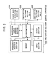
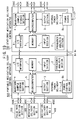
- FIG. 3 is a block diagram showing the composition of the medication delivery regulation apparatus which pertains to the present embodiment.
- pulse detector (200) employs a pressure detection part such as a skew gauge and a cuff to press the pressure detection part against the radial artery, measures the pressure on the pressure detector, and outputs a pulse wave signal (analog signal). Additionally, the pulse detector is used to measure the blood pressure, by measuring the blood pressure pulse wave from said skew gauge and outputting the result.
- Medication delivery sections no. 1 (300) and no. 2 (400) are composed of micropumps and their drive circuits, and depending on the control of medication delivery control apparatus (100), they dispense ⁇ -blocker and ⁇ -blocker to the respective patients.
- Medication delivery control apparatus (100) is composed of memory (1), input section (7), output section (3), waveform sample storage section (4), frequency analysis section (2), and microcomputer (5).
- Memory (1) is a stable memory device composed of a RAM (random access memory) with a battery backup, and is used for the temporary storage of control data when the microcomputer (5) controls the-parts of the medication delivery control apparatus (100). Furthermore, in a prescribed memory area of memory (1), the data represented by graphs A1 and B1 of the previously mentioned figures 1 and 2 are stored as the ⁇ -dominant state defining data and the data represented by graphs A2 and B2 of said figures 1 and 2 are stored as the ⁇ -dominant state defining data.
- the medication delivery control apparatus (100) pertaining to the present embodiment is composed such that, besides carrying out medication delivery control using fixed ⁇ -dominant state defining data and ⁇ -dominant state defining data, it can generate ⁇ -dominant state defining data and ⁇ -dominant state defining data based on the pulse wave spectrum of an individual patient, and carry out medication delivery control using ⁇ -dominant state defining data and ⁇ -dominant state defining data generated in this way.
- ⁇ -dominant state defining data and ⁇ -dominant state defining data generated in this manner is stored.
- Input section (7) is provided as a means for entering commands into microcomputer (5), and is composed of such items as a keyboard.
- Output section (3) is composed of such items as a printer and a display device, and according to the control of the microcomputer, the devices perform the recording of pulse spectra obtained from the patient, recording of the medication delivery, and the display of the pulse waves.
- Waveform sample storage section (4) receives a waveform signal outputted by the pulse wave detector (200) and stores one wavelength (one cycle) of the received signal as a sample.
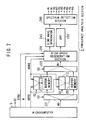
- the composition of the waveform sample storage section (4) is explained with reference to figure 4.
- (101) is an A/D (analog to digital) converter, which converts the pulse wave signal output by pulse wave detector (200) into a digital signal according to a sampling clock ⁇ with a fixed cycle.
- (102) is a lowpass filter,which, for the digital signals sequentially output by the A/D converter (101), undergoes a procedure to remove the components above a fixed cutoff frequency, and outputs the results sequentially as the waveform value W.
- (103) is the waveform memory composed from RAM, and it sequentially stores the waveform value W received through the lowpass filter (102).
- (111) is the waveform value address counter, and when the waveform gathering command START is output from the microcomputer (5), it counts the sampling clock ⁇ and sends the results of the count to the address input end of waveform memory (103) as the waveform address ADR1 for writing in the waveform value W.
- This waveform address ADR1 is monitored by the microcomputer (5).
- (121) is the derivation circuit, and it calculates the time derivatives of the waveform values sequentially output from the lowpass filter (102).
- (122) is the zero-cross detection circuit, which outputs the zero-cross detection pulse Z when the waveform value's time derivative becomes equal to zero. More specifically, zero-cross detection circuit (122) is provided in order to detect the peak points on the waveform of the pulse wave as given in figure 5 as an example, and when the waveform values W corresponding to these peak points are input then it outputs zero-cross detection pulse Z.
- (123) is a peak address counter, which, when the microcomputer outputs the waveform gathering command START, counts the zero-cross detection pulses Z, and outputs the results of the count as the peak address ADR2.
- (124) is a movement average calculation circuit, which calculates the average value of the time derivatives of a pre-determined number of waveforms output from the derivation circuit (121) up until the appropriate time, and outputs the results as slope data SLP which represent the slopes of the waveform up until the appropriate time.
- (125) is a peak data storage memory provided in order to store the peak data discussed below.
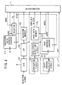
- This frequency analysis section (2) cyclically receives the waveform value WD through microcomputer (5) from the waveform memory (103) of the waveform sample storage section (4), regenerates the received waveform value WD at high speed, and calculates the spectrum composing the pulse wave by analyzing the frequency of each cycle. Additionally, this frequency analysis section (2) calculates first the fundamental spectrum, then the second harmonic spectrum, and so on, going through the respective spectra composing the pulse waves sequentially.
- the microcomputer (5) when outputting the first waveform value WD of one cycle of a pulse wave to the frequency analysis section (2), in addition to outputting the synchronous signal SYNC and the number N of waveform values WD included in the cycle, switches the select signal S2. Additionally, microcomputer (5), while outputting one cycle of the waveform values WD, sequentially outputs the write-in address ADR5 which changes from 0 to N - 1 in synchronization with the delivery of each waveform value WD.
- the buffer memories (201) and (202) are provided for the collection of the waveform values WD output from the microcomputer (5).
- the distributor (221) outputs the waveform values WD of the pulse waves received through the microcomputer from the waveform sample storage section (4) to either buffer memory (201) or buffer memory (202) depending on the direction indicated by the select signal S2.
- Selector (222) selects the buffer memory indicated by the select signal S2 out of buffer memory (201) or buffer memory (202), and outputs the waveform value WH read from the buffer memory to the high-speed regeneration section (230) discussed below.
- Selectors (211) and (212) select either the write-in address ADR5 or the read-out address ADR6 (discussed below) generated by the high-speed regeneration section (230) according to the select signal S2, and delivers them to buffer memories (201) and (202).
- High-speed regeneration section (230) is a means for reading out the waveform values corresponding to each cycle from buffer memories (201) and (202), and outputs the read-out address ADR6 by varying it over an interval of 0 to N - 1 (wherein N is the number of waveform values to be read out). More specifically, this high-speed regeneration section (230), while the respective waveform values WD corresponding to a certain cycle are being written into one of the buffer memories, generates the above-mentioned read-out address ADR6 , and repeatedly reads out all of the waveform values WD corresponding to the previous cycle from the other buffer memory.
- the generation of read-out address ADR6 is controlled so that all of the waveform values WD corresponding to a single cycle can always be entirely read out in a fixed period of time.
- the time interval for reading out all of the waveform values for a complete cycle corresponds to the degree of the spectrum being detected; that is, T for detecting the fundamental spectrum, 2T for the second degree spectrum, 3T for the third degree spectrum, and so on.
- the high-speed regeneration section (230) contains an interpolation mechanism which interpolates the waveform values WH read out from the buffer memories (201) and (202), and outputs them as the waveform values of a fixed sampling frequency m/T (m is a fixed integer).
- Bandpass filter (250) has the fixed value 1/T as the central frequency of its pass band.
- Sine wave generator (240) is a variable frequency waveform generator, and, according to the control of microcomputer (5), it sequentially generates sine waves of period T, 2T, 3T, 4T, 5T, and 6T corresponding to the degree of the spectrum to be detected.
- Spectrum measurement section (260) measures the amplitudes H 1 to H 6 of each of the spectra of the pulse waves based on the output signal level of the bandpass filter (250) and also measures the phase ⁇ 1 to ⁇ 6 of each of the spectra based on the difference between the phase of the output signal of the bandpass filter (250) and the phase of the sine wave output by the sine wave generator (240).
- Microcomputer (5) controls the various sections of the present apparatus (100) in accordance with commands input through the input section (7). Furthermore, microcomputer (5) contains a clock circuit, and in the active mode for carrying out the medication delivery control, performs the respective procedures given below upon the passing of a standard time interval.
- the waveforms are sequentially read out from the waveform memory (103) within the waveform sample storage section (4) and output to the frequency analysis section (5) as waveform data WD. Then, the waveform spectrum output by frequency analysis section (5) is compared with the ⁇ -dominant state defining data and ⁇ -dominant state defining data, and it is determined whether or not the patient is in a state of excitation of the ⁇ -receptors or ⁇ -receptors.
- a drive command is delivered to medication delivery section no. 2 and ⁇ -blocker is given; and if the patient's ⁇ -receptors are in an excited state and the patient's blood pressure is at a value requiring medication, then a drive command is delivered to medication delivery section no. 1 and ⁇ -blocker is given.
- FIG 8 shows medication delivery section no. 1, or equivalently, medication delivery section no. 2 (400).
- (301) is a micropump, and its inlet port (305) is attached through the tube (305T) to the medication tank (361) which is filled with ⁇ -blocker or ⁇ -blocker, and its outlet port (306) is attached through the tube (306T) to the syringe (362) for dispensing the medication.
- the drive circuit (363) generates a drive pulse of a standard level (approx. 100V) upon receiving a drive order from the microcomputer (5), and sends it to the piezoelectric element (326) which is the drive means for the micropump (301).
- Oscillator circuit (364) generates a number of pulses the pulse widths of which are shorter than the pulse widths of the above-mentioned drive pulses, and sends them to the action detection switch (350) of micropump (301) through the capacitor (C) and the resistor (R).
- the action detection switch (350) is constructed so that it is only turned on for a fixed period of time each time fluid is released from the outlet port (306) of micropump (301).
- the problem detection circuit (365) commutes the voltage on both ends of the action detection switch (350), and sends out a problem detection signal if the voltage level taken from the commutation does not exhibit temporal changes corresponding to the drive pulses.
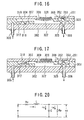
- FIG 9 is a cross-sectional view of the micropump (301) comprising the medication delivery section.
- This micropump (301) is constructed by sandwiching the thin board (303) between the base board (302) and the surface board (304).
- the base board (302) is composed of, for example, a glass board of thickness approximately 1 mm, and is provided with an inlet port (305) and an outlet port (306). To these ports, tubes (305T) and (306T) are attached with adhesive so as to prevent the occurrence of fluid leaks.
- the thin board (303) is composed of, for example, a silicon board of thickness approximately 0.3 mm, and due to etching an inlet bulb (307) and an outlet bulb (308) are formed in addition to a diaphragm (309) between the bulbs. Furthermore, a pump chamber (322) beneath the diaphragm (309) and a pump flow system going through it are formed as well. Above the diaphragm (309), as a drive means, a piezodisc element (326) is attached.
- Inlet bulb (307) is formed by covering over the base board (302), and at the approximate center of its top surface is formed a pass hole (318) as well as a valve (316) which protrudes down to surround the pass hole (318). The end section of this valve (316) impinges on the base board (302), and a chamber (317) is formed from the side of the inlet bulb (307) and the valve (316). This chamber (317) is attached to the inlet port (305) through a flow route not shown in the drawing.
- Outlet port (308) is comprised of a valve (325) which covers the opening of the outlet port (306) in a cap-like fashion.
- a surface board (304) composed of the same kind of glass board as the base board (302) is attached by an anode attachment method, and the top wall of a part of the flow route of the above-mentioned pump flow system is comprised of this surface board (304).
- a window (328) is formed on a part of this surface board (304) corresponding to the above-mentioned diaphragm (309) .
- the above-mentioned piezoelectric element (326) is attached through this window (328) on the surface of the exposed diaphragm (309) mentioned above.
- the thickness of the surface board is (304) is approximately 1 mm.
- This action detection switch (350) is provided in order to detect movements in a partition of the outlet bulb (308), and is comprised of a protuberance (351) which projects above said partition, an electrode (352) attached to the surface of this protuberance (351), and an opposite electrode (353) attached to the bottom of the surface board (304).
- the output pulse of the oscillation route (364) is sent through the capacitor (C) and the resistor (R) to to the electrodes (352) and (353).
- the electrodes (352) and (353) such materials as Pt-Ir, W, Ta, Ni, Pt, Pd, Mo, Ti, polycrystalline Si, WSi 2 , CP1, or CP2 may be used on the contacts.
- the medication delivery regulation apparatus controls the delivery of medication to the patient based on ⁇ -dominant state defining data and ⁇ -dominant state defining data which has been pre-stored in memory (1) as explained below.
- ⁇ -dominant state defining data ⁇ -dominant state defining data
- ⁇ -dominant state defining data which has been pre-stored in memory (1) as explained below.
- the operator inputs the corresponding command from input section (2).
- the microcomputer (5) writes into the memory (1) the initial value of the remaining amount of ⁇ -blocker and ⁇ -blocker (relative to the amount in one tankful).
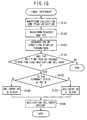
- microcomputer (5) contains a clock circuit, and a timer interrupt signal is generated after the clock circuit measures out a fixed time interval. Then, upon generation of this timer interrupt signal the microcomputer (5) runs the timer interrupt routine shown in the flow chart of figure 10.
- step S101 a procedure to gather waveforms and their peak data are run.
- the waveform gathering command START is output by microcomputer (5), and the waveform address counter (111) inside the waveform sample storage section (4) and the peak address counter (123) are reset.
- the count of the sampling clock ⁇ is started by the waveform address counter (111), and that count value is delivered to the waveform memory (103) as the waveform address ADR1.
- the radial artery waveforms detected by the pulse wave detector (200) are input into the A/D converter (101), sequentially converted into digital signals according to the sampling clock ⁇ , and sequentially output through the lowpass filter (102) as the waveform values W.
- the output waveform values W are sequentially delivered to the waveform memory (103), and written into the appropriate memory area by the waveform address ADR1 depending on the time. Due to the above operation a series of waveform values W corresponding to the radial artery waveforms given as examples in figure 5 are collected in the waveform memory (103).
- the detection and writing into the peak data memory (125) of the peak data is performed as explained below.
- the time derivatives of the waveform values W output from the lowpass filter (102) are calculated by the derivation circuit (121), and these time derivatives are entered into the zero cross detection circuit (122) and the movement average calculation circuit (124).
- the movement average calculation circuit in this way calculates the average values of a pre-set number of time derivatives (that is, movement average values) each time the time derivative values of the waveform values W are delivered.
- the slope information is output as a positive value
- the slope information is output as a negative value.
- microcomputer (5) generates the peak type B/T based on the sign of the slope data SLP.
- the microcomputer (5) lets the peak data B/T correspond to a maximum value.
- the peak type B/T in this case, bottom B
- the microcomputer delivers an address "1" smaller than the peak address ADR2 to the peak data memory (125) as the read-out memory ADR3, and the waveform value W first written in is read out.
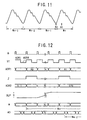
- microcomputer (5) sequentially reads out the waveform values from the waveform memory (103) located in the waveform sample storage section (4), and sends them to the frequency analysis section (2) as the waveform data WD. Below, the procedure is explained with reference to figures 11 and 12.
- the select signal S1 is switched in time with the clock ⁇ , and at the same time the write-in/read-out modes of the waveform memory (103) are switched.
- the microcomputer (5) checks the contents of the above-mentioned shift register, determines the difference between the waveform address of the first minimum of pulse wave W n - 2 and the waveform address of the first minimum of the next pulse wave W n - 1 , that is, the number N of waveform values contained in a single period of the pulse wave W n - 1 , and outputs it to the frequency analysis section (2) with the synchronous signal SYNC. Also, the select signal S2 is switched synchronously with the synchronous signal SYNC, and the interior connection state of the distributor (221), the selectors (211) and (212), and the selector (222) go into the state shown by the full lines in figure 7.
- the microcomputer (5) sequentially increases the read-out address ADR4 from the waveform address of the first minimum value of the pulse wave W n - 2 , and delivers them to the waveform memory (103) through the selector (112).
- the read-out address ADR4 is changed at a faster rate (twice as fast, for example) than the write-in address. This is so that all of the waveform values corresponding to the pulse wave W n - 2 before pulse wave W n-1 are read out before the maximum value of the pulse wave W n + 1 coming after pulse wave W n is entered into the waveform sample storage section (4).
- the microcomputer (5) reads out the waveform values WD of the pulse wave W n - 2 from two periods ago, sends them to the frequency analysis section (2), and sequentially delivers them through the distributor (221) to the buffer memory (201). While the waveform values WD are being sequentially delivered to the buffer memory (201) in this way, the write-in address ADR5 increases from 0 to N - 1, and this write-in address ADR5 is delivered to the buffer memory (201) through the selector (211). As a result, at each memory area of each address 0 to N - 1 in the buffer memory (201) each waveform value WD corresponding to the pulse wave W n - 2 is accumulated.
- the read-out address ADR6 is output from the high-speed regeneration section (230), and delivered to the buffer memory (202) through the selector (212).
- each waveform value WD corresponding to the pulse wave W n - 3 a single period prior to pulse wave W n - 2 is read out, and entered into the high-speed regeneration section (230) through the selector (222).
- the waveform values WD corresponding to the pulse wave W n - 3 contained in the buffer memory (202) are read out several times at a higher speed than the waveform values corresponding to the pulse wave W n - 2 contained in buffer memory (201) can be accumulated. On this occasion, so that the waveform values WD corresponding to the pulse wave W n - 3 may all be read out within the set time period, the speed increase of the read-out address ADR6 is controlled.
- the high-speed regeneration section (230) increases the read-out address ADR6 at high speed, and if the number is a small value N2 as shown in figure 14, then it increases the read-out address at low speed, and it is made so that the read-out address ADR6 changes between 0 to N1 - 1 or 0 to N2 - 1 within the set time period T. Then, the waveform values WD read out in this way are given an interpolation calculation in the high-speed regeneration section (230), and are delivered to the bandpass filter (250) as the waveform values WH of a set sampling frequency m/T.
- the bandpass filter (250) chooses and lets pass the signals with frequency 1/T out of the time series data of the waveform values WH, and delivers them to the spectrum measurement section (260).
- the sine wave generator (240) generates a sine wave of period T as shown in figure 15 and delivers it to the spectrum measurement section (260).
- the spectrum measurement section (260) measures the output signal level of the bandpass filter (250) depending on the frequency, outputs a representative value as the amplitude H 1 of the fundamental wave spectrum of the pulse wave W n - 3 , measures the phase difference between the output signal of the bandpass filter (250) and the sine wave generated by the sine wave generator (240), and outputs a representative value as the phase ⁇ 1 of the fundamental spectrum of the pulse wave W n-3 . For each representative value, the average shift value of the phase and the output signal levels corresponding to each wave, for example, right before outputting the fundamental wave spectrum, are calculated.
- the high-speed regeneration section (230) sets the speed increase of the read-out address ADR6 at one half that of the measurement of the above-mentioned fundamental wave spectrum so that all of the waveform values of the pulse wave W n - 3 can be read out within the set time period 2T, repeatedly reads out the waveform values WH corresponding to the pulse wave W n - 3 , and delivers them to the bandpass filter (250) (see figure 15). Then, out of the time series data of the waveform values WH, the signals with a frequency 1/T, that is, the signals corresponding to the second harmonic waves of the pulse wave W n - 3 pass through the bandpass filter (250) and are delivered to the spectrum measurement section (260).
- the spectrum measurement section (260) measures and outputs the amplitude H 2 of the second harmonic spectrum of the pulse wave W n-3 .
- the sine wave generator (240) generates a sine wave with period 2T and delivers it to the spectrum measurement section (260) (see figure 15).
- the spectrum measurement section (260) outputs the phase ⁇ 2 of the fundamental spectrum of the pulse wave W n-3 .
- the speed increase of the read-out address ADR6 is sequentially changed over to 1/3, 1/4, 1/5, and 1/6 of the case for the fundamental wave spectrum while the periods of the sine waves generated by the sine wave generator (240) are changed to 3T, 4T, 5T, and 6T, the same procedure as above is repeated, and the amplitudes H 3 to H 6 and the phases ⁇ 3 to ⁇ 6 of the third to sixth harmonic spectra are output from the spectrum measurement section (260).
- the respective spectra of the pulse wave W n-3 determined in this manner are entered into the microcomputer (5).
- the microcomputer (5) generates the synchronous signal SYNC and outputs the number N of waveform values WD contained in the pulse wave W n - 2 . Additionally, the select signal S2 gets switched, and the connection state of the distributor (221), the selectors (211) and (212), and the selector (221) goes into the state shown by the dotted lines in figure 7.
- the microcomputer (6) reads out from the waveform memory the waveform values WD of the pulse wave W n - 1 two cycles before it and sends them to the frequency analysis section (2), and sequentially delivers them through the distributor (221) to the buffer memory (202). Similar to this procedure, the waveform values WD corresponding to the pulse wave W n - 2 one cycle before pulse wave W n - 1 are read out from the buffer memory (201), and after they are interpolated by the high-speed regeneration section (230) they are output as the waveform values WH. Then, for the waveform values WH corresponding to the pulse wave W n - 2 , the same procedure is taken as for the pulse wave W n - 3 , and the spectrum is thus determined.
- the microcomputer (5) collects the respective spectra of the pulse waves determined in S102 together with information on the present time and date into the memory (1), and writes the amplitude ratios between the respective harmonic spectra and the fundamental spectrum contained in the pulse waves, and the phases of the respective harmonic spectra into the memory (1) as the condition displaying parameters.
- step S104 referring to the time at which the last medication delivery was carried out recorded in the memory (1) and the output of the clock circuit, it is determined whether or not the required time interval has passed since the last delivery of medication. If the determination is "Yes” then the procedure advances to step S105, and if "No” then the timer interrupt routine is ended. The reason for including such a determination is to prevent the repeated delivery of the same type of blocker before the effects of the medication appear.
- step S105 the condition display parameters stored in the memory (1) are compared with the ⁇ -dominant state defining data and ⁇ -dominant state defining data.
- the procedure advances to step S106.
- the blood pressure value is determined by the pulse waves of the patient measured by the pulse wave detector (200), and if the value indicates the need for medication delivery then an activation order is sent to medication delivery section no. 1 (300) according to the set number of times for performing the delivery of ⁇ -blocker.
- step S107 If the condition display parameters agree with the ⁇ -dominant state defining data within some set error limits then the procedure advances to step S107, where, similar to step S106, if the blood pressure value of the patient indicates the need for medication delivery then an activation order is sent to medication delivery section no. 2 (400) according to the set number of times for performing the delivery of ⁇ -blocker. If the condition display parameters are different from either the ⁇ -dominant state defining data or the ⁇ -dominant state defining data then the timer interrupt routine is ended.
- the activation circuit (363) When the activation order is generated by the microcomputer (5), the following action is taken by the medication delivery section (300) or (400) which received it.
- the activation circuit (363) generates an activation pulse of a set level (approx. 100V) upon receiving an activation order from the microcomputer, and delivers it to the piezoelectric element (326) in the micropump (301).
- the piezoelectric element (326) changes shape as shown in figure 16, and the diaphragm (309) gets pushed down.
- the pressure inside the pump chamber (322) increases, the protuberance on the outlet bulb (309) gets pushed up, and the valve (325) comes away from the base board (302).
- the blocker inside the pump chamber (322) flows through the seam between the valve (325) and the base board (302) and out of the outlet port (306), and is delivered to the patient through the tube (306T) and the syringe (362).
- the activation pulse goes down, as shown in figure 17, since the diaphragm (309) attempts to return to its original shape from the state in which it was bent inward, a reduction of pressure results in the pump chamber (322). Because of this, the outlet port (306) is closed off by the valve (325) of the outlet bulb (308) being pushed against the base board, and the protuberance on the inlet bulb (307) gets pushed upwards, and the valve (316) comes away from the base board (302).
- blocker flows in through the inlet bulb (305), and gets sucked into the pump chamber (322) through the seam between the valve (316) and the base board (302) and the pass hole (318). Subsequently, each time an activation pulse is received blocker is let out and sucked in as explained above.
- the problem detection circuit (365) outputs a problem detection signal to the microcomputer (5) if it detects such a shift.
- the microcomputer (5) upon receiving the problem detection signal, displays an alarm through the output section (3) and prompts the user to change needles.
- step S 108 Upon the completion of step S106 or S107 the procedure advances to step S 108, where according to the number of activation orders generated the dosage to be delivered is calculated, and this dosage, the type of blocker used ( ⁇ -blocker/ ⁇ -blocker), and the time of the medication delivery are written into the memory (1) as the medication delivery record data.
- the medication delivery record data written into the memory (1) can be output through the output section (3) due to the input of a command through the input section (7).
- a doctor can use this medication delivery record data in order to diagnose any changes in the patient's condition.
- step S108 the remaining amount of the blocker used in the current medication delivery is read out from the memory (1), the amount used in the medication delivery is subtracted from this amount and the result is written into the memory (1) as the new remaining amount.
- the microcomputer (5) sends a warning through the output section (3).
- the output section (3) prompts the user to change the medication tank through an alarm display such as a warning lamp.
- the warning may also be conveyed through the use of a sound.
- the user can set the pattern memorization/automatic drive mode as the activation mode by inputting a command through the input section (7).
- the ⁇ -dominant state defining data and ⁇ -dominant state defining data are based on spectra of pulse waves taken from the patient, and afterwards, the ⁇ -dominant state defining data and ⁇ -dominant state defining data generated in such a manner are used in order to control the medication delivery.
- the actions involved in this activation mode are explained.
- step S201 the respective procedures for waveform collecting and peak detecting are run, then in step S202, the sampling procedure and FFT of a single wavelength of the pulse wave are run.
- step S203 the state defining data (the ⁇ -dominant state defining data and ⁇ -dominant state defining data) are calculated based on the spectra of the pulse wave obtained in step S202. Then, advancing to step S204, it is determined whether the generated state defining data are ⁇ -dominant or ⁇ -dominant, and according to this determination, the calculation result in step S203 is written into the memory (1) as either ⁇ -dominant state defining data (step S205) or ⁇ -dominant state defining data (step S206).
- the start commands for medication delivery control based on the relevant state defining data are entered into the input section (2).
- the timer interrupt routine is run at fixed time intervals.
- the ⁇ -dominant state defining data and ⁇ -dominant state defining data taken from the patient in the above manner are the basis for medication delivery control.
- the composition of the second embodiment of the present invention is shown in figure 19.
- (700) is a stationary medication delivery control apparatus to be fixed to the side of a hospital bed
- (800) is a portable medication delivery control apparatus to be attached to the patient
- these apparatuses have a composition similar to the medication delivery control apparatus (100) of the first embodiment. Accordingly, regarding these apparatuses (700) and (800), the parts corresponding to the respective parts in the above-mentioned medication delivery control apparatus (100) are given the same reference symbols and their explanation is omitted, while below, only the parts differing from the apparatus (100) are explained.
- Both medication delivery control devices (700) and (800) are provided with microcomputers (5) with I/O interfaces (6) in order to carry out mutual communication.
- Exterior devices such as the pulse wave detection section (200), medication delivery section no. 1 (300), and medication delivery section no. 2 (400) are connected to the stationary medication delivery control apparatus (700) or the portable medication delivery control apparatus (800) by means of their respective cables (200C), (300C), and (400C).
- cables (200C), (300C), and (400C) Inside each cable (200C), (300C), and (400C) is a signal line and a power line; the transfer of signals between the medication delivery control apparatus and each exterior device is performed through the signal lines, while the delivery of electricity is performed through the power lines.
- the portable medication delivery control apparatus (800) has a power control section (8b) for delivering power from a battery which is charged through charging electrodes (8d) to the interior sections of the apparatus and to the exterior devices through the above-mentioned power lines. Because the portable medication delivery control apparatus (800) uses a battery as its power source, in order to save energy, the delivery of power is controlled by the power control section (8b) through the microcomputer (5). That is, under the control of the microcomputer (5), when the timer interrupt routine is activated, power is delivered from the power control section (8b) to the interior sections of the apparatus only while it is necessary, and otherwise, power is only delivered to the microcomputer (5).
- the power control section (8b) employs a voltage monitoring circuit which outputs an alarm signal when the output voltage of the battery becomes lower than a set value. This alarm signal is sent to the microcomputer (5), and upon receiving such an alarm signal the microcomputer (5) generates a warning by activating a warning means such as an LED or a warning sound generator.
- the stationary medication delivery control apparatus (700) has a power source (8a), and this power source (8a) relies on a commercial power source in order to deliver power to the interior of the apparatus as well as such exterior devices as the pulse wave detection section. Furthermore, the output voltage of the power source (8a) is designed to be output to the voltage output electrodes (8c), the battery in the portable medication delivery control apparatus (800) can be charged by connecting the charging electrodes (8d) to these electrodes (8c).
- the medication delivery control apparatuses (700) and (800) of the present embodiment obtain their data through the I/O interfaces (6), and the following uses are possible.
- condition display parameters waveform parameters, as in steps S102 and S103 of figure 10
- it was determined whether or not to deliver medication based on these condition display parameters step S105.
- the present embodiment not forming part of the invention uses a method in which the value of each element in a Four Element Concentration Constant Model which models the patient's circulatory movement based on the pulse waves taken from the patent is determined, and the results are used as the condition display parameters.
- the Four Element Concentration Constant Model observes the four parameters which govern the action of the human circulatory system, that is, the inertia of the blood in the central arteries, the blood vessel resistance in the central arteries due to blood viscosity (viscous resistance), the compliance of the blood vessels in the central arteries (viscoelasticity), and the blood vessel resistance in the capillaries (viscous resistance), and models them on an electric circuit.
- Figure 20 shows the circuit diagram for the Four Element Concentration Constant Model. Below, the relationships between the respective elements which make up the Four Element Concentration Constant Model and the above-mentioned parameters are shown.
- the compliance is a measure of the softness of the blood vessels, and it refers to the viscoelasticity.
- the electrical currents i, i p , and i c flowing in the electrical circuit correspond to the blood flow [cm 3 /s] flowing in the respective sections.
- the input voltage e applied to this circuit corresponds to the pressure x 10 -7 J/cm 3 (dyn/cm 2 ) at the origin of the aorta.
- the voltage v p across the capacitance C corresponds to the pressure x 10 -7 J/cm 3 (dyn/cm 2 ) at the radial artery.
- the micrometer (5) has read out a single cycle of the pulse wave from the waveform memory (103) as per step S102, a simulation is run on the above-mentioned Four Element Concentration Constant Model in which an electronic signal is given which corresponds to a pressure wave in the aortic origin. Then, the values of the respective elements in the Four Element Concentration Constant Model of the pulse wave read out from the waveform memory (103) are calculated, and the results of the calculation are used as the condition display parameters.
- step S105 the values of the respective elements of the Four Element Concentration Constant Model for the ⁇ -dominant state defining data and ⁇ -dominant state defining data, which were prepared as pre-determined conditional parameters, are compared with the above-mentioned condition display parameters, and the condition of the patient is determined.
- the distortion d of the pulse wave is calculated from the frequency spectrum of the pulse wave, and the medication delivery control is carried out based on the distortion.
- the distortion d may be determined by sampling the low frequency and high frequency components of the pulse waves by inputting the pulse waves into low pass and high pass filters, then obtaining the direct current signals W1 and W2 by rectifying and smoothing these high frequency and low frequency components, and taking W2/W1.
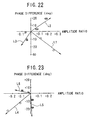
- FIGs 22 and 23 show the types of changes in the phase and amplitude of the pulse wave spectra due to the delivery of medication; specifically, figure 22 shows the case for the second harmonics, and figure 23 shows the case for the third harmonics.
- the vertical axis represents the phase change in each harmonic wave due to the medication delivery
- the horizontal axis represents the change in the ratio between the amplitude of the fundamental wave and the harmonic wave.
- the respective plots connected by the lines L1 and L4 show the case in which nifedipine is given
- the respective plots connected by the lines L2 and L5 show the case in which phentolamine is given
- the respective plots connected by the lines L3 and L6 show the case in which propranolol is given.
- the delivery of nifedipine results in a delay in the phase and an increase in amplitude
- the delivery of propranolol results in a phase delay and a decrease in amplitude
- the delivery of phentolamine results in an advance in phase and an increase in amplitude.
- the delivery of nifedipine results in a phase delay and a decrease in amplitude
- the delivery of propranolol results in a decrease in amplitude
- the delivery of phentolamine results in a phase delay.
- the amount of change in the phase and amplitude depends upon the amount of medication given.
- the data given in figures 22 and 23 are used in medication delivery control. That is, for the present example, the occurrence of the condition requiring the delivery of medication is determined by detecting phase delays or amplitude changes in the second harmonic waves of the patient's pulse waves, and thus the necessary delivery of medication is performed.
Landscapes
- Health & Medical Sciences (AREA)
- Life Sciences & Earth Sciences (AREA)
- Engineering & Computer Science (AREA)
- Medical Informatics (AREA)
- Surgery (AREA)
- Cardiology (AREA)
- Physics & Mathematics (AREA)
- Veterinary Medicine (AREA)
- Biophysics (AREA)
- Pathology (AREA)
- Biomedical Technology (AREA)
- Heart & Thoracic Surgery (AREA)
- Public Health (AREA)
- Molecular Biology (AREA)
- General Health & Medical Sciences (AREA)
- Animal Behavior & Ethology (AREA)
- Vascular Medicine (AREA)
- Physiology (AREA)
- Medicinal Chemistry (AREA)
- Chemical & Material Sciences (AREA)
- Bioinformatics & Cheminformatics (AREA)
- Pharmacology & Pharmacy (AREA)
- Measuring Pulse, Heart Rate, Blood Pressure Or Blood Flow (AREA)
- Infusion, Injection, And Reservoir Apparatuses (AREA)
Claims (11)
- Medikamentenabgabe-Regulierungsvorrichtung, die umfaßt:dadurch gekennzeichnet, daß die Wellenformparameter Amplitudenverhältnisse der entsprechenden Oberwellenspektren und der Grundspektren der Pulswellen enthalten; undeine Pulswellenerfassungsvorrichtung, die ein Pulswellenerfassungsmittel (200) zum Erfassen der Pulswellen eines Patienten sowie ein Pulswellenanalysemittel (100) zum Ermitteln des Pulswellenspektrums mittels Frequenzanalyse der Pulswellen und zum Berechnen der Wellenformparameter auf der Grundlage der durch die Frequenzanalyse ermittelten Pulswellenspektren umfaßt;ein Mittel zum Messen eines Blutdrucks des obenerwähnten Patienten; undein Medikamentenabgabe-Steuermittel (100, 300, 400) zum Anordnen der Abgabe eines Medikaments, wenn die Wellenformparameter festgelegte Bedingungen erfüllen;
das Medikamentenabgabe-Steuermittel (100, 300, 400) so konfiguriert ist, daß es die Abgabe des Medikaments anordnet, wenn die Amplitudenverhältnisse die festgelegten Bedingungen erfüllen und der Blutdruck größer ist als ein festgelegter Wert. - Medikamentenabgabe-Regulierungsvorrichtung, die umfaßt:dadurch gekennzeichnet, daß die Wellenformparameter Phasendifferenzen zwischen den jeweiligen Oberwellenspektren und den Grundspektren der Pulswellen enthalten; undeine Pulswellenerfassungsvorrichtung, die ein Pulswellenerfassungsmittel (200) zum Erfassen der Pulswellen eines Patienten sowie ein Pulswellenanalysemittel (100) zum Ermitteln des Pulswellenspektrums mittels Frequenzanalyse der Pulswellen und zum Berechnen der Wellenformparameter auf der Grundlage der durch die Frequenzanalyse ermittelten Pulswellenspektren umfaßt;ein Mittel zum Messen eines Blutdrucks des obenerwähnten Patienten; undein Medikamentenabgabe-Steuerrnittel (100, 300, 400) zum Anordnen der Abgabe eines Medikaments, wenn die Wellenformparameter festgelegte Bedingungen erfüllen;
das Medikamentenabgabe-Steuermittel (100, 300, 400) so konfiguriert ist, daß es die Abgabe des Medikaments anordnet, wenn die Phasendifferenzen die festgelegten Bedingungen erfüllen und der Blutdruck größer ist als ein festgelegter Wert. - Medikamentenabgabe-Regulierungsvorrichtung, die umfaßt:dadurch gekennzeichnet, daß das Pulswellenanalysemittel (100) die Hochfrequenz- und Niedrigfrequenz-Komponenten der Pulswellen erfaßt, und die Wellenformparameter die Verhältnisse zwischen den Hochfrequenz-Komponenten und den Niedrigfrequenz-Komponenten der Pulswellen enthalten; undeine Pulswellenerfassungsvorrichtung, die ein Pulswellenerfassungsmittel (200) zum Erfassen der Pulswellen eines Patienten sowie ein Pulswellenanalysemittel (100) zum Ermitteln des Pulswellenspektrums mittels Frequenzanalyse der Pulswellen und zum Berechnen der Wellenformparameter auf der Grundlage der durch die Frequenzanalyse ermittelten Pulswellenspektren umfaßt;ein Mittel zum Messen eines Blutdrucks des obenerwähnten Patienten; undein Medikamentenabgabe-Steuermittel (100, 300, 400) zum Anordnen der Abgabe eines Medikaments, wenn die Wellenformparameter festgelegte Bedingungen erfüllen;
das Medikamentenabgabe-Steuermittel (100, 300, 400) so konfiguriert ist, daß es die Abgabe des Medikaments anordnet, wenn die Verhältnisse die festgelegten Bedingungen erfüllen und der Blutdruck größer ist als ein festgelegter Wert. - Medikamentenabgabe-Regulierungsvorrichtung, die umfaßt:dadurch gekennzeichnet, daß die Signalformparameter die Verzerrungen der Pulswellen enthalten, die aus den Pulswellenspektren berechnet worden sind; undeine Pulswellenerfassungsvorrichtung, die ein Pulswellenerfassungsmittel (200) zum Erfassen der Pulswellen eines Patienten sowie ein Pulswellenanalysemittel (100) zum Ermitteln des Pulswellenspektrums mittels Frequenzanalyse der Pulswellen und zum Berechnen der Wellenformparameter auf der Grundlage der durch die Frequenzanalyse ermittelten Pulswellenspektren umfaßt;ein Mittel zum Messen eines Blutdrucks des obenerwähnten Patienten; undein Medikamentenabgabe-Steuermittel (100, 300, 400) zum Anordnen der Abgabe eines Medikaments, wenn die Wellenformparameter festgelegte Bedingungen erfüllen;
das Medikamentenabgabe-Steuermittel (100, 300, 400) so konfiguriert ist, daß es die Abgabe des Medikaments anordnet, wenn die Verzerrungen die festgelegten Bedingungen erfüllen und der Blutdruck größer ist als ein festgelegter Wert. - Medikamentenabgabe-Regulierungsvorrichtung nach Anspruch 4, in der die Verzerrung der Wert ist, der erhalten wird durch Dividieren der Quadratwurzel der Summe der Quadrate der Amplituden der entsprechenden Oberwellen durch die Amplitude der Grundwelle, oder durch Dividieren der Summe der Amplituden der entsprechenden Oberwellen durch die Amplitude der Grundwelle.
- Medikamentenabgabe-Regulierungsvorrichtung nach irgendeinem der vorangehenden Ansprüche, in der ein Setzmittel vorgesehen ist, um die vom obenerwähnten Frequenzanalyseabschnitt ermittelten Wellenformparameter als die Bedingungen für die Medikamentenabgabe zu setzen.
- Medikamentenabgabe-Regulierungsvorrichtung nach irgendeinem der vorangehenden Ansprüche, in der ein erstes Alarmmittel vorgesehen ist zum Ermitteln der Menge des an den obenerwähnten Patienten abgegebenen Medikaments, und zum Ausgeben eines Alarms, wenn der Summierungswert der Medikamentenabgabewerte eine gesetzte Menge erreicht, und/oder ein zweites Alarmmittel vorgesehen ist, um zu beobachten, ob die Medikamentenabgabe normal durchgeführt wird, und zum Ausgeben eines Alarms, wenn irgendwelche Probleme auftreten.
- Medikamentenabgabe-Regulierungsvorrichtung nach irgendeinem der vorangehenden Ansprüche, in der die Medikamentenabgabe-Regulierungsvorrichtung tragbar ist, eine Batterie und ein Stromsteuermittel (8b) besitzt, um die Ausgangsspannung der Batterie den jeweils relevanten Elementen nur dann zuzuführen, wenn die Sammlung der Pulswellen durch das obenerwähnte Pulswellenerfassungsmittel (200), die Berechnung der obenerwähnten Wellenformparameter durch das obenerwähnte Pulswellenanalysemittel (100) und die obenerwähnte Medikamentenabgabe durch das obenerwähnte Medikamentenabgabesteuermittel durchgeführt werden.
- Medikamentenabgabe-Regulierungsvorrichtung nach Anspruch 8, in der ein Alarmmittel vorgesehen ist, um einen Alarm auszugeben, wenn die Spannung der obenerwähnten Batterie unter eine festgelegte Spannung sinkt.
- Medikamentenabgabe-Regulierungsvorrichtung nach irgendeinem der vorangehenden Ansprüche, in der ein Speicher und ein Medikamentenabgabeaufzeichnungsmittel vorgesehen sind, um Medikamentenabgabedaten aufzuzeichnen, die die Zeit, den Typ des Medikaments und/oder die bei jeder Durchführung der Medikamentenabgabe abgegebene Menge darstellen.
- Medikamentenabgabe-Regulierungsvorrichtung nach Anspruch 10, in der ein Kommunikationsmittel vorgesehen ist, über das die obenerwähnten Medikamentenabgabedaten von externen Vorrichtungen in den obenerwähnten Speicher übertragen werden können.
Applications Claiming Priority (3)
| Application Number | Priority Date | Filing Date | Title |
|---|---|---|---|
| JP30054893 | 1993-11-30 | ||
| JP30054893A JP3409399B2 (ja) | 1993-11-30 | 1993-11-30 | 投薬制御装置 |
| JP300548/93 | 1993-11-30 |
Publications (3)
| Publication Number | Publication Date |
|---|---|
| EP0664102A2 EP0664102A2 (de) | 1995-07-26 |
| EP0664102A3 EP0664102A3 (de) | 1995-11-08 |
| EP0664102B1 true EP0664102B1 (de) | 2002-04-17 |
Family
ID=17886160
Family Applications (1)
| Application Number | Title | Priority Date | Filing Date |
|---|---|---|---|
| EP94308782A Expired - Lifetime EP0664102B1 (de) | 1993-11-30 | 1994-11-28 | Vorrichtung zur Steuerung der Medikamenten-Abgabe und zur Bestimmung der Pulssignale |
Country Status (4)
| Country | Link |
|---|---|
| US (1) | US5730137A (de) |
| EP (1) | EP0664102B1 (de) |
| JP (1) | JP3409399B2 (de) |
| DE (1) | DE69430419T2 (de) |
Cited By (11)
| Publication number | Priority date | Publication date | Assignee | Title |
|---|---|---|---|---|
| US8560345B2 (en) | 2006-03-28 | 2013-10-15 | Hospira, Inc. | Medication administration and management system and method |
| US9971871B2 (en) | 2011-10-21 | 2018-05-15 | Icu Medical, Inc. | Medical device update system |
| US10042986B2 (en) | 2013-11-19 | 2018-08-07 | Icu Medical, Inc. | Infusion pump automation system and method |
| US10238801B2 (en) | 2009-04-17 | 2019-03-26 | Icu Medical, Inc. | System and method for configuring a rule set for medical event management and responses |
| US10242060B2 (en) | 2006-10-16 | 2019-03-26 | Icu Medical, Inc. | System and method for comparing and utilizing activity information and configuration information from multiple medical device management systems |
| US10238799B2 (en) | 2014-09-15 | 2019-03-26 | Icu Medical, Inc. | Matching delayed infusion auto-programs with manually entered infusion programs |
| US10311972B2 (en) | 2013-11-11 | 2019-06-04 | Icu Medical, Inc. | Medical device system performance index |
| US10314974B2 (en) | 2014-06-16 | 2019-06-11 | Icu Medical, Inc. | System for monitoring and delivering medication to a patient and method of using the same to minimize the risks associated with automated therapy |
| US10333843B2 (en) | 2013-03-06 | 2019-06-25 | Icu Medical, Inc. | Medical device communication method |
| US11594326B2 (en) | 2018-07-17 | 2023-02-28 | Icu Medical, Inc. | Detecting missing messages from clinical environment |
| US12040068B2 (en) | 2018-07-17 | 2024-07-16 | Icu Medical, Inc. | Reducing file transfer between cloud environment and infusion pumps |
Families Citing this family (42)
| Publication number | Priority date | Publication date | Assignee | Title |
|---|---|---|---|---|
| WO1994015526A1 (fr) * | 1993-01-07 | 1994-07-21 | Seiko Epson Corporation | Analyseur d'onde d'impulsion, et appareil de diagnostic l'utilisant |
| WO1996035368A1 (en) * | 1995-05-12 | 1996-11-14 | Seiko Epson Corporation | Apparatus for diagnosing condition of living organism and control unit |
| CN1154432C (zh) * | 1995-11-01 | 2004-06-23 | 精工爱普生株式会社 | 用于测量生理状态的装置 |
| DE19542019C1 (de) * | 1995-11-10 | 1997-03-06 | Fraunhofer Ges Forschung | Sensor zum nichtinvasiven und kontinuierlichen Erfassen der arteriellen Pulswellenlaufzeit |
| US5879307A (en) * | 1996-03-15 | 1999-03-09 | Pulse Metric, Inc. | Non-invasive method and apparatus for diagnosing and monitoring aortic valve abnormalities, such a aortic regurgitation |
| ITFI960154A1 (it) * | 1996-06-27 | 1997-12-29 | Giglio Mauro Del | Metodo e sistema per la terapia delle aritmie ipercinetiche atriali |
| US6002952A (en) | 1997-04-14 | 1999-12-14 | Masimo Corporation | Signal processing apparatus and method |
| US6231560B1 (en) * | 1999-02-10 | 2001-05-15 | Baxter International Inc | Method and apparatus for automatically controlling the level of medication |
| US6942622B1 (en) | 1999-11-10 | 2005-09-13 | Pacesetter, Inc. | Method for monitoring autonomic tone |
| US8152789B2 (en) | 2001-10-23 | 2012-04-10 | Medtronic Minimed, Inc. | System and method for providing closed loop infusion formulation delivery |
| US6827702B2 (en) | 2001-09-07 | 2004-12-07 | Medtronic Minimed, Inc. | Safety limits for closed-loop infusion pump control |
| AU2002329964A1 (en) * | 2001-09-07 | 2003-03-24 | Medtronic Minimed, Inc. | Safety limits for closed-loop infusion pump control |
| US6575912B1 (en) * | 2001-10-16 | 2003-06-10 | Pacesetter, Inc. | Assessing heart failure status using morphology of a signal representative of arterial pulse pressure |
| US6561984B1 (en) * | 2001-10-16 | 2003-05-13 | Pacesetter, Inc. | Assessing heart failure status using morphology of a signal representative of arterial pulse pressure |
| US20040073175A1 (en) * | 2002-01-07 | 2004-04-15 | Jacobson James D. | Infusion system |
| US8065161B2 (en) | 2003-11-13 | 2011-11-22 | Hospira, Inc. | System for maintaining drug information and communicating with medication delivery devices |
| US9123077B2 (en) | 2003-10-07 | 2015-09-01 | Hospira, Inc. | Medication management system |
| WO2005112762A1 (en) * | 2004-05-14 | 2005-12-01 | Florida Atlantic University | Device and methods for monitoring and regulating anticoagulation therapy |
| CN100496388C (zh) * | 2005-08-31 | 2009-06-10 | 深圳迈瑞生物医疗电子股份有限公司 | 利用信号变换计算血压的装置 |
| US9386925B2 (en) * | 2006-05-11 | 2016-07-12 | MEDIMETRICS Personalized Drug Delivery B.V. | Device for drug administration and/or monitoring the status of a patient |
| US8435184B2 (en) | 2007-01-31 | 2013-05-07 | Aortic Wrap Pty Ltd. | Characterisation of ageing effect and cardiovascular risk |
| DE102008011873A1 (de) | 2007-12-30 | 2009-07-09 | Idelevich, Evgeny | Applikationsvorrichtung und -verfahren zur automatisierten Medikamentenabgabe bei arteriellem Hypertonus |
| US20090247982A1 (en) * | 2008-03-27 | 2009-10-01 | Lifescan Inc. | Medical Device Mechanical Pump |
| EP2967502A4 (de) * | 2013-03-15 | 2016-11-16 | Intelomed Inc | System und verfahren zur charakterisierung eines zirkulierenden blutflusses |
| US20150066531A1 (en) | 2013-08-30 | 2015-03-05 | James D. Jacobson | System and method of monitoring and managing a remote infusion regimen |
| US9662436B2 (en) | 2013-09-20 | 2017-05-30 | Icu Medical, Inc. | Fail-safe drug infusion therapy system |
| US11259745B2 (en) | 2014-01-28 | 2022-03-01 | Masimo Corporation | Autonomous drug delivery system |
| US9764082B2 (en) | 2014-04-30 | 2017-09-19 | Icu Medical, Inc. | Patient care system with conditional alarm forwarding |
| AU2016267761B2 (en) | 2015-05-26 | 2021-02-11 | Icu Medical, Inc. | Infusion pump system and method with multiple drug library editor source capability |
| US20210110901A1 (en) * | 2015-12-31 | 2021-04-15 | Koninklijke Philips N.V. | Magnetic-resonance imaging data synchronizer |
| EP3449818A4 (de) * | 2016-04-27 | 2019-04-17 | Asahi Kasei Kabushiki Kaisha | Vorrichtung, endgerät und system für biometrische informationen |
| US11574737B2 (en) | 2016-07-14 | 2023-02-07 | Icu Medical, Inc. | Multi-communication path selection and security system for a medical device |
| WO2019169026A1 (en) * | 2018-03-01 | 2019-09-06 | Masimo Corporation | Autonomous drug delivery system |
| US11483403B2 (en) | 2018-07-17 | 2022-10-25 | Icu Medical, Inc. | Maintaining clinical messaging during network instability |
| US10861592B2 (en) | 2018-07-17 | 2020-12-08 | Icu Medical, Inc. | Reducing infusion pump network congestion by staggering updates |
| US10692595B2 (en) | 2018-07-26 | 2020-06-23 | Icu Medical, Inc. | Drug library dynamic version management |
| CA3107315C (en) | 2018-07-26 | 2023-01-03 | Icu Medical, Inc. | Drug library management system |
| AU2020267477B2 (en) | 2019-05-08 | 2025-09-18 | Icu Medical, Inc. | Threshold signature based medical device management |
| US11590057B2 (en) | 2020-04-03 | 2023-02-28 | Icu Medical, Inc. | Systems, methods, and components for transferring medical fluids |
| WO2022051230A1 (en) | 2020-09-05 | 2022-03-10 | Icu Medical, Inc. | Identity-based secure medical device communications |
| US11291769B1 (en) * | 2020-12-03 | 2022-04-05 | Perceptive Medical Inc. | Systems and methods for regulating fluid infusion in a patient |
| CN114652275B (zh) * | 2022-03-10 | 2025-05-23 | 福州九候生医科技有限公司 | 脉搏波数据处理方法及相关设备 |
Citations (1)
| Publication number | Priority date | Publication date | Assignee | Title |
|---|---|---|---|---|
| EP0630608A1 (de) * | 1993-01-07 | 1994-12-28 | Seiko Epson Corporation | Pulswellen-analysator als teil eines diagnose-gerätes |
Family Cites Families (16)
| Publication number | Priority date | Publication date | Assignee | Title |
|---|---|---|---|---|
| US4080966A (en) * | 1976-08-12 | 1978-03-28 | Trustees Of The University Of Pennsylvania | Automated infusion apparatus for blood pressure control and method |
| US4245648A (en) * | 1978-09-20 | 1981-01-20 | Trimmer Gordon A | Method and apparatus for measuring blood pressure and pulse rate |
| US4425920A (en) * | 1980-10-24 | 1984-01-17 | Purdue Research Foundation | Apparatus and method for measurement and control of blood pressure |
| US4710164A (en) * | 1984-05-01 | 1987-12-01 | Henry Ford Hospital | Automated hemodialysis control based upon patient blood pressure and heart rate |
| CA1254091A (en) * | 1984-09-28 | 1989-05-16 | Vladimir Feingold | Implantable medication infusion system |
| JPS61272034A (ja) * | 1985-05-27 | 1986-12-02 | 三菱電機株式会社 | 呼吸循環機能測定装置 |
| DE3609912A1 (de) * | 1986-03-24 | 1987-10-08 | Franz Theo Dr Med Ernst | Messverfahren und geraet zur vereinfachten messung des blutdrucks und des pulses |
| US5269301A (en) * | 1987-10-06 | 1993-12-14 | Leonard Bloom | Multimode system for monitoring and treating a malfunctioning heart |
| JP2570329B2 (ja) * | 1987-11-18 | 1997-01-08 | 日本電装株式会社 | 覚醒度判定装置 |
| JP2770413B2 (ja) * | 1989-01-26 | 1998-07-02 | 株式会社デンソー | 生体異常判定装置 |
| ES2014727A6 (es) * | 1989-07-04 | 1990-07-16 | Borches Jacassa Daniel | Perfeccionamientos en los sistemas de administracion de farmacos. |
| JP2855767B2 (ja) * | 1990-03-28 | 1999-02-10 | オムロン株式会社 | 電子血圧計 |
| JPH04285530A (ja) * | 1991-03-14 | 1992-10-09 | Omron Corp | 波形判別装置 |
| JPH04300562A (ja) * | 1991-03-28 | 1992-10-23 | Unitika Ltd | 電気的薬剤導入装置 |
| JP3084694B2 (ja) * | 1992-04-03 | 2000-09-04 | 株式会社ニッショー | 血圧監視機能付き血液透析装置 |
| US5381797A (en) * | 1993-03-26 | 1995-01-17 | Pak; Song C. | Pulse diagnostic device and method of measuring a pulse wave using this device |
-
1993
- 1993-11-30 JP JP30054893A patent/JP3409399B2/ja not_active Expired - Lifetime
-
1994
- 1994-11-22 US US08/343,301 patent/US5730137A/en not_active Expired - Lifetime
- 1994-11-28 DE DE69430419T patent/DE69430419T2/de not_active Expired - Lifetime
- 1994-11-28 EP EP94308782A patent/EP0664102B1/de not_active Expired - Lifetime
Patent Citations (1)
| Publication number | Priority date | Publication date | Assignee | Title |
|---|---|---|---|---|
| EP0630608A1 (de) * | 1993-01-07 | 1994-12-28 | Seiko Epson Corporation | Pulswellen-analysator als teil eines diagnose-gerätes |
Cited By (11)
| Publication number | Priority date | Publication date | Assignee | Title |
|---|---|---|---|---|
| US8560345B2 (en) | 2006-03-28 | 2013-10-15 | Hospira, Inc. | Medication administration and management system and method |
| US10242060B2 (en) | 2006-10-16 | 2019-03-26 | Icu Medical, Inc. | System and method for comparing and utilizing activity information and configuration information from multiple medical device management systems |
| US10238801B2 (en) | 2009-04-17 | 2019-03-26 | Icu Medical, Inc. | System and method for configuring a rule set for medical event management and responses |
| US9971871B2 (en) | 2011-10-21 | 2018-05-15 | Icu Medical, Inc. | Medical device update system |
| US10333843B2 (en) | 2013-03-06 | 2019-06-25 | Icu Medical, Inc. | Medical device communication method |
| US10311972B2 (en) | 2013-11-11 | 2019-06-04 | Icu Medical, Inc. | Medical device system performance index |
| US10042986B2 (en) | 2013-11-19 | 2018-08-07 | Icu Medical, Inc. | Infusion pump automation system and method |
| US10314974B2 (en) | 2014-06-16 | 2019-06-11 | Icu Medical, Inc. | System for monitoring and delivering medication to a patient and method of using the same to minimize the risks associated with automated therapy |
| US10238799B2 (en) | 2014-09-15 | 2019-03-26 | Icu Medical, Inc. | Matching delayed infusion auto-programs with manually entered infusion programs |
| US11594326B2 (en) | 2018-07-17 | 2023-02-28 | Icu Medical, Inc. | Detecting missing messages from clinical environment |
| US12040068B2 (en) | 2018-07-17 | 2024-07-16 | Icu Medical, Inc. | Reducing file transfer between cloud environment and infusion pumps |
Also Published As
| Publication number | Publication date |
|---|---|
| EP0664102A3 (de) | 1995-11-08 |
| JPH07148253A (ja) | 1995-06-13 |
| EP0664102A2 (de) | 1995-07-26 |
| DE69430419T2 (de) | 2002-08-08 |
| JP3409399B2 (ja) | 2003-05-26 |
| DE69430419D1 (de) | 2002-05-23 |
| US5730137A (en) | 1998-03-24 |
Similar Documents
| Publication | Publication Date | Title |
|---|---|---|
| EP0664102B1 (de) | Vorrichtung zur Steuerung der Medikamenten-Abgabe und zur Bestimmung der Pulssignale | |
| CN101198278B (zh) | 一种血压测量装置 | |
| CN105726006B (zh) | 用于连续估计心血管参数的脉搏轮廓方法和装置 | |
| US7309313B2 (en) | Vascular disease examining system and bypass vascular diagnosing device | |
| JP5449793B2 (ja) | 生理学的パラメータを求めるための装置および方法 | |
| CN102387741B (zh) | 使用动脉压波形数据的血管状态的检测 | |
| EP1992282B1 (de) | Verfahren zur nicht-invasiven bestimmung einer endothelfunktion und vorrichtung zur durchführung dieses verfahrens | |
| JPH03202072A (ja) | 脈管内注入における異常を検出するための装置 | |
| WO2001078597A1 (en) | Method and apparatus for monitoring cardiovascular condition | |
| US20100210957A1 (en) | Blood pressure measurement device and control method of the same | |
| US4872461A (en) | Electronic blood pressure meter having improved cuff repressurization means | |
| JP2010110375A (ja) | 血圧情報測定装置 | |
| CN100448395C (zh) | 血压测量装置 | |
| CN113440114B (zh) | 一种基于薄膜压力传感器的脉搏波优选方法及装置 | |
| US6585658B2 (en) | System and method for the automatic evaluation of the indexes of volemic status | |
| JP2004121866A (ja) | 生体状態測定装置 | |
| JP2012200507A (ja) | 電子血圧計および演算プログラム | |
| JPH08191808A (ja) | 生体電気インピーダンス測定装置 | |
| EP1420687B1 (de) | Verfahren zur messung des arteriolendrucks | |
| KR100452748B1 (ko) | 전자 혈압계를 이용한 심전도 측정 방법 | |
| CN110881956A (zh) | 心脏生理参数测量方法、设备、终端及计算机存储介质 | |
| JP3491076B2 (ja) | 血圧測定装置 | |
| JP4091972B1 (ja) | 血管機能診断システムとプログラム | |
| JPH08173390A (ja) | 診断装置 | |
| JPH08299458A (ja) | 投薬制御装置 |
Legal Events
| Date | Code | Title | Description |
|---|---|---|---|
| PUAI | Public reference made under article 153(3) epc to a published international application that has entered the european phase |
Free format text: ORIGINAL CODE: 0009012 |
|
| AK | Designated contracting states |
Kind code of ref document: A2 Designated state(s): DE FR GB |
|
| PUAL | Search report despatched |
Free format text: ORIGINAL CODE: 0009013 |
|
| AK | Designated contracting states |
Kind code of ref document: A3 Designated state(s): DE FR GB |
|
| 17P | Request for examination filed |
Effective date: 19960415 |
|
| 17Q | First examination report despatched |
Effective date: 19980910 |
|
| GRAG | Despatch of communication of intention to grant |
Free format text: ORIGINAL CODE: EPIDOS AGRA |
|
| GRAG | Despatch of communication of intention to grant |
Free format text: ORIGINAL CODE: EPIDOS AGRA |
|
| GRAH | Despatch of communication of intention to grant a patent |
Free format text: ORIGINAL CODE: EPIDOS IGRA |
|
| GRAH | Despatch of communication of intention to grant a patent |
Free format text: ORIGINAL CODE: EPIDOS IGRA |
|
| REG | Reference to a national code |
Ref country code: GB Ref legal event code: IF02 |
|
| GRAA | (expected) grant |
Free format text: ORIGINAL CODE: 0009210 |
|
| AK | Designated contracting states |
Kind code of ref document: B1 Designated state(s): DE FR GB |
|
| REF | Corresponds to: |
Ref document number: 69430419 Country of ref document: DE Date of ref document: 20020523 |
|
| ET | Fr: translation filed | ||
| PLBE | No opposition filed within time limit |
Free format text: ORIGINAL CODE: 0009261 |
|
| STAA | Information on the status of an ep patent application or granted ep patent |
Free format text: STATUS: NO OPPOSITION FILED WITHIN TIME LIMIT |
|
| 26N | No opposition filed |
Effective date: 20030120 |
|
| PGFP | Annual fee paid to national office [announced via postgrant information from national office to epo] |
Ref country code: DE Payment date: 20121121 Year of fee payment: 19 Ref country code: FR Payment date: 20121130 Year of fee payment: 19 |
|
| PGFP | Annual fee paid to national office [announced via postgrant information from national office to epo] |
Ref country code: GB Payment date: 20121128 Year of fee payment: 19 |
|
| GBPC | Gb: european patent ceased through non-payment of renewal fee |
Effective date: 20131128 |
|
| REG | Reference to a national code |
Ref country code: FR Ref legal event code: ST Effective date: 20140731 |
|
| REG | Reference to a national code |
Ref country code: DE Ref legal event code: R119 Ref document number: 69430419 Country of ref document: DE Effective date: 20140603 |
|
| PG25 | Lapsed in a contracting state [announced via postgrant information from national office to epo] |
Ref country code: DE Free format text: LAPSE BECAUSE OF NON-PAYMENT OF DUE FEES Effective date: 20140603 |
|
| PG25 | Lapsed in a contracting state [announced via postgrant information from national office to epo] |
Ref country code: GB Free format text: LAPSE BECAUSE OF NON-PAYMENT OF DUE FEES Effective date: 20131128 Ref country code: FR Free format text: LAPSE BECAUSE OF NON-PAYMENT OF DUE FEES Effective date: 20131202 |