EP0662598B1 - Hydraulische Fülleinrichtung und Verwendung der Fülleinrichtung zur Befüllung und Entlüftung von Waffen-Rohrbremsen und Waffen-Rohrvorholern - Google Patents
Hydraulische Fülleinrichtung und Verwendung der Fülleinrichtung zur Befüllung und Entlüftung von Waffen-Rohrbremsen und Waffen-Rohrvorholern Download PDFInfo
- Publication number
- EP0662598B1 EP0662598B1 EP94119937A EP94119937A EP0662598B1 EP 0662598 B1 EP0662598 B1 EP 0662598B1 EP 94119937 A EP94119937 A EP 94119937A EP 94119937 A EP94119937 A EP 94119937A EP 0662598 B1 EP0662598 B1 EP 0662598B1
- Authority
- EP
- European Patent Office
- Prior art keywords
- filling
- recoil
- hydraulic
- tank
- connection
- Prior art date
- Legal status (The legal status is an assumption and is not a legal conclusion. Google has not performed a legal analysis and makes no representation as to the accuracy of the status listed.)
- Expired - Lifetime
Links
- 230000000740 bleeding effect Effects 0.000 title claims description 4
- 239000007788 liquid Substances 0.000 title 1
- 239000012530 fluid Substances 0.000 claims description 6
- 239000011521 glass Substances 0.000 claims description 5
- 238000000034 method Methods 0.000 claims description 4
- 238000009423 ventilation Methods 0.000 description 10
- 239000003921 oil Substances 0.000 description 9
- 238000013022 venting Methods 0.000 description 8
- 238000012423 maintenance Methods 0.000 description 5
- 239000010720 hydraulic oil Substances 0.000 description 4
- 238000005429 filling process Methods 0.000 description 2
- 239000006260 foam Substances 0.000 description 2
- 230000003139 buffering effect Effects 0.000 description 1
- 239000000383 hazardous chemical Substances 0.000 description 1
- 231100000206 health hazard Toxicity 0.000 description 1
- 230000007257 malfunction Effects 0.000 description 1
- 238000005507 spraying Methods 0.000 description 1
- 231100000331 toxic Toxicity 0.000 description 1
- 230000002588 toxic effect Effects 0.000 description 1
Images
Classifications
-
- F—MECHANICAL ENGINEERING; LIGHTING; HEATING; WEAPONS; BLASTING
- F16—ENGINEERING ELEMENTS AND UNITS; GENERAL MEASURES FOR PRODUCING AND MAINTAINING EFFECTIVE FUNCTIONING OF MACHINES OR INSTALLATIONS; THERMAL INSULATION IN GENERAL
- F16F—SPRINGS; SHOCK-ABSORBERS; MEANS FOR DAMPING VIBRATION
- F16F9/00—Springs, vibration-dampers, shock-absorbers, or similarly-constructed movement-dampers using a fluid or the equivalent as damping medium
- F16F9/32—Details
- F16F9/43—Filling or drainage arrangements, e.g. for supply of gas
Definitions
- the invention relates to a hydraulic filling device for filling and bleeding gun barrel brakes and barrel advancer according to the preamble of claim 1.
- Filling devices of this type are known per se and are used for basic or maintenance filling of hydraulic pipe brakes or pipe recoilers of artillery weapons, for example known from DE-30 15 097 C2.
- the filling device essentially consists of a tank containing the hydraulic fluid, a pump with filling line and, if necessary, a control device such as that e.g. from DE-37 33 215 A1 (closest prior art) is known.
- Air pockets in the oil space of hydraulic actuators are often responsible for their malfunction. For example, air pockets in the oil space of gun pipe brakes or corresponding pipe pre-catchers during the return of the pipe uncontrollable pressure rises and buffering when feeding the pipe. As a rule, the hydraulic actuators must be filled air-free with the corresponding hydraulic fluid (eg oil), ie during the filling process and afterwards the actuators must be thoroughly vented.
- the corresponding hydraulic fluid eg oil
- the invention has for its object to further develop the hydraulic filling device mentioned at the outset in such a simple manner that when appropriate hydraulic actuators are vented through the spraying out Hydraulic fluid no pollution harmful to the environment occur. In addition, there should be no health hazards for maintenance personnel associated with the ventilation.
- the invention is based on the idea of not inserting the ventilation hose into an open vessel as before, but connecting it to the tank of the filling device.
- the foam of the hydraulic fluid flows directly back into the tank of the filling device via the venting hose. This hydraulic fluid can be fed back to the actuator when the filling process is continued.
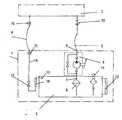
- 1 is a filling device according to the invention and 2 is a hydraulic actuator known per se to be filled, e.g. the pipe brake of an artillery weapon.
- the filling device 1 and the pipe brake 2 are connected to one another via a filling hose 3 and a ventilation hose 4.
- the filling device 1 essentially consists of an at least partially filled with hydraulic oil tank 5 and a pump 6.
- the pump 6 can be, for example act as a piston hand pump. While a suction pipe 7 with a suction filter 8 protruding into the tank 5 is arranged on the suction connection of the pump 6, the pressure connection of the pump is connected to a filling connection 9 of the filling device 1.
- the filling hose 3 is fastened between this filling connection 9 and a corresponding filling connection 10 on the pipe brake 2.
- the tank 5 of the filling device 1 has a filling and ventilation filter 11 and has an oil level indicator 12 for checking the oil level.
- one end 13 of a vent line 14 projects into the tank 5.
- the corresponding other end of the vent line 14 is connected to a vent connection 15 of the filling device 1.
- the vent hose 4 is fastened between this port 15 and a vent port 16 of the pipe brake 2.
- a shut-off valve 17 and a ventilation sight glass 18 are also arranged in the ventilation line 14.
- the filling device 1 is connected to the pipe brake 2 with the aid of the filling hose 3 and the ventilation hose 4.
- the shut-off valve 17 initially remains closed.
- the pipe brake 2 By actuating the piston hand pump 6, the pipe brake 2 is filled with hydraulic oil. The air in the pipe brake 2 is compressed. After opening the shut-off valve 17, the pipe brake 2 is vented into the tank 5 via the vent hose 4 and the vent line 14. Of the Venting level can be checked on the venting sight glass 18.
Landscapes
- Engineering & Computer Science (AREA)
- General Engineering & Computer Science (AREA)
- Mechanical Engineering (AREA)
- Valves And Accessory Devices For Braking Systems (AREA)
- Transmission Of Braking Force In Braking Systems (AREA)
- Braking Arrangements (AREA)
- Fluid-Pressure Circuits (AREA)
Description
- Die Erfindung betrifft eine hydraulische Fülleinrichtung zum Befüllen und Entlüften von Waffenrohrbremsen und Waffenrohrvorholern nach dem Oberbegriff des Patentanspruchs 1.
- Derartige Fülleinrichtungen sind an sich bekannt und dienen zur Grund- oder Wartungsfüllung von beispielsweise aus der DE-30 15 097 C2 bekannten hydraulischen Rohrbremsen bzw. Rohrvorholern von Artilleriewaffen. Die Fülleinrichtung besteht dabei im wesentlichen aus einem die Hydraulikflüssigkeit enthaltenden Tank, einer Pumpe mit Fülleitung und ggf. einer Steuervorrichtung, wie sie z.B. aus der DE-37 33 215 A1 (nächtstliegender Stand der Technik) bekannt ist.
- Lufteinschlüsse im Ölraum hydraulischer Stellglieder sind häufig für deren Fehlfunktionen verantwortlich. So bewirken beispielsweise Lufteinschlüsse im Ölraum von Waffen-Rohrbremsen oder entsprechenden Rohrvorholern beim Rücklauf des Rohres unkontrollierbare Druckanstiege und beim Vorlauf des Rohres Pufferungen. Die hydraulischen Stellglieder müssen daher in der Regel luftfrei mit der entsprechenden Hydraulikflüssigkeit (z.B. Öl) gefüllt werden, d.h. während des Füllvorganges und im Anschluß daran müssen die Stellglieder gründlich entlüftet werden.
- Es ist bekannt, die hydraulischen Stellglieder manuell zu entlüften. Hierzu befindet sich an dem jeweiligen Stellglied ein Entlüftungsanschluß, an dem ein Entlüftungsschlauch befestigt wird. Der Entlüftungsschlauch hängt bei dem Entlüftungsvorgang mit seinem dem Entlüftungsanschluß abgewandten Ende in einem in der Regel offenem Gefäß (Eimer, Dose o.ä.).
- Nachteilig ist bei dieser bekannten manuellen Entlüftung, daß das austretende Hydrauliköl schäumend in das offene Gefäß spritzt. Es besteht daher die Gefahr, daß sich das Wartungspersonal mit Öl beschmutzt und die Umwelt zusätzlich belastet wird. Außerdem besteht für das Wartungspersonal die Gefahr einer gesundheitlichen Schädigung, da das Öl gering toxisch ist. Das entnommene Hydrauliköl muß anschließend über ein Filtersystem gereinigt und kann erst dann dem hydraulischen Element wieder zugeführt werden. Allerdings wird in der Regel das beim Entlüftungsvorgang entnommene Öl nicht dem Kessel wieder zugeleitet, sondern relativ aufwendig entsorgt.
- Der Erfindung liegt die Aufgabe zugrunde, die eingangs erwähnte hydraulische Fülleinrichtung auf einfache Weise derart weiterzuentwickeln, daß beim Entlüften entsprechender hydraulischer Stellglieder durch die herausspritzende Hydraulikflüssigkeit keine die Umwelt belastende Verschmutzungen auftreten. Außerdem sollen mit der Entlüftung keine Gesundheitsgefahren für das Wartungspersonal verbunden sein.
- Diese Aufgabe wird durch die Merkmale des kennzeichnenden Teiles des Anspruchs 1 gelöst. Weitere vorteilhafte Ausgestaltungen der Erfindung offenbaren die Unteransprüche.
- Im wesentlichen liegt der Erfindung der Gedanke zugrunde, den Entlüftungsschlauch nicht wie bisher in ein offenes Gefäß einzuführen, sondern mit dem Tank der Fülleinrichtung zu verbinden. Über den Entlüftungsschlauch fließt dann beim Entlüften des jeweiligen Stellgliedes der Schaum der Hydraulikflüssigkeit direkt in den Tank der Fülleinrichtung zurück. Diese Hydraulikflüssigkeit kann bei der Fortsetzung des Füllvorganges dem Stellglied wieder zugeführt werden.
- Weitere Einzelheiten und Vorteile der Erfindung ergeben sich aus dem folgenden anhand einer Figur erläuterten bevorzugten Ausführungsbeispiel.
- In der Figur ist mit 1 eine erfindungsgemäße Fülleinrichtung und mit 2 ein an sich bekanntes zu befüllendes hydraulisches Stellglied, z.B. die Rohrbremse einer Artilleriewaffe, bezeichnet. Die Fülleinrichtung 1 und die Rohrbremse 2 sind über einen Füllschlauch 3 und einen Entlüftungsschlauch 4 miteinander verbunden.
- Die Fülleinrichtung 1 besteht im wesentlichen aus einem mindestens teilweise mit Hydrauliköl gefüllten Tank 5 und einer Pumpe 6. Bei der Pumpe 6 kann es sich beispielsweise um eine Kolbenhandpumpe handeln. Während an dem Sauganschluß der Pumpe 6 ein in den Tank 5 hineinragendes Saugrohr 7 mit Saugfilter 8 angeordnet ist, ist der Druckanschluß der Pumpe mit einem Füllanschluß 9 der Fülleinrichtung 1 verbunden. Zwischen diesem Füllanschluß 9 und einem entsprechenden Füllanschluß 10 an der Rohrbremse 2 wird der Füllschlauch 3 befestigt.
- Der Tank 5 der Fülleinrichtung 1 besitzt ein Einfüll- und Belüftungsfilter 11 und weist zur Kontrolle des Ölstandes eine Ölstandsanzeige 12 auf. Außerdem ragt das eine Ende 13 einer Entlüftungsleitung 14 in den Tank 5 hinein. Das entsprechende andere Ende der Entlüftungsleitung 14 ist mit einem Entlüftungsanschluß 15 der Fülleinrichtung 1 verbunden. Zwischen diesem Anschluß 15 und einem Entlüftungsanschluß 16 der Rohrbremse 2 wird der Entlüftungsschlauch 4 befestigt.
- In der Entlüftungsleitung 14 ist ferner ein Absperrhahn 17 und ein Entlüftungsschauglas 18 angeordnet.
- Im folgenden wird kurz auf die Wirkungsweise der erfindungsgemäßen Fülleinrichtung 1, z.B. bei einer Wartungsfüllung, eingegangen: Die Fülleinrichtung 1 wird hierzu mit Hilfe des Füllschlauches 3 und des Entlüftungsschlauches 4 mit der Rohrbremse 2 verbunden. Der Absperrhahn 17 bleibt dabei zunächst geschlossen.
- Durch Betätigung der Kolbenhandpumpe 6 wird die Rohrbremse 2 mit Hydrauliköl gefüllt. Die in der Rohrbremse 2 befindliche Luft wird verdichtet. Nach dem Öffnen des Absperrhahnes 17 wird die Rohrbremse 2 über den Entlüftungsschlauch 4 und die Entlüftungsleitung 14 in den Tank 5 entlüftet. Der Entlüftungsstand kann dabei am Entlüftungsschauglas 18 kontrolliert werden.
- Für eine vollständige Entlüftung muß der Vorgang "Füllen/Entlüften" mehrfach wiederholt werden, bis keine Luftblasen mehr in dem Entlüftungsschauglas zu sehen sind.
-
- 1
- hydraulische Fülleinrichtung
- 2
- hydraulisches Stellglied, Rohrbremse
- 3
- Füllschlauch
- 4
- Entlüftungsschlauch
- 5
- Tank
- 6
- Pumpe
- 7
- Saugrohr
- 8
- Saugfilter
- 9,10
- Füllanschlüsse
- 11
- Einfüll- und Belüftungsfilter
- 12
- Ölstandsanzeige
- 13
- Ende der Entlüftungsleitung
- 14
- Entlüftungsleitung
- 15,16
- Entlüftungsanschlüsse
- 17
- Absperrhahn
- 18
- Entlüftungsschauglas
Claims (1)
- Hydraulische Fülleinrichtung zum Befüllen mit Hydraulikflüssigkeit und Entlüften von hydraulischen Waffenrohrbremsen oder Waffenrohrvorholern (2), wobei die Fülleinrichtung (1) einen die Hydraulikflüssigkeit enthaltenden Tank (5) sowie eine Pumpe (6) und die Waffenrohrbremse oder der Waffenrohrvorholer (2) jeweils einen Füllanschluß (10) und einen Enlüftungsanschluß (16) aufweisen, und daß bei bestimmungsgemäßer Verwendung der Fülleinrichtung (1) diese über eine Fülleitung (3) mit dem Füllanschluß (10) verbindbar ist, dadurch gekennzeichnet, daß an dem Tank (5) eine Entlüftungsleitung (4/14) angeschlossen ist, die während des Befüllungs- und Entlüftungsvorganges mit dem Entlüftungsanschluß (16) der Waffenrohrbremse oder des Waffenrohrvorholers (2) verbunden ist, und daß die Entlüftungsleitung (4/14) einen Absperrhahn (17) aufnimmt, und daß zwischen dem Absperrhahn (17) und dem Tank (5) in der Entlüftungsleitung (14) ein Entlüftungsschauglas (18) angeordnet ist.
Applications Claiming Priority (2)
| Application Number | Priority Date | Filing Date | Title |
|---|---|---|---|
| DE4400325 | 1994-01-07 | ||
| DE4400325A DE4400325A1 (de) | 1994-01-07 | 1994-01-07 | Hydraulische Fülleinrichtung und Verwendung der Fülleinrichtung zur Befüllung und Entlüftung von Waffen-Rohrbremsen und Waffen-Rohrvorholern |
Publications (3)
| Publication Number | Publication Date |
|---|---|
| EP0662598A2 EP0662598A2 (de) | 1995-07-12 |
| EP0662598A3 EP0662598A3 (de) | 1996-02-28 |
| EP0662598B1 true EP0662598B1 (de) | 1997-08-27 |
Family
ID=6507571
Family Applications (1)
| Application Number | Title | Priority Date | Filing Date |
|---|---|---|---|
| EP94119937A Expired - Lifetime EP0662598B1 (de) | 1994-01-07 | 1994-12-16 | Hydraulische Fülleinrichtung und Verwendung der Fülleinrichtung zur Befüllung und Entlüftung von Waffen-Rohrbremsen und Waffen-Rohrvorholern |
Country Status (3)
| Country | Link |
|---|---|
| US (1) | US5555919A (de) |
| EP (1) | EP0662598B1 (de) |
| DE (2) | DE4400325A1 (de) |
Cited By (1)
| Publication number | Priority date | Publication date | Assignee | Title |
|---|---|---|---|---|
| CN101520061B (zh) * | 2009-04-14 | 2013-06-12 | 西安飞机工业(集团)有限责任公司 | 液压系统减缓冲击压力的方法及装置 |
Families Citing this family (7)
| Publication number | Priority date | Publication date | Assignee | Title |
|---|---|---|---|---|
| US20050133304A1 (en) * | 1991-10-23 | 2005-06-23 | Viken James P. | Fluid exchange system for vehicles |
| US6378657B2 (en) | 1991-10-23 | 2002-04-30 | James P. Viken | Fluid exchange system |
| US5944068A (en) * | 1997-02-13 | 1999-08-31 | Kelsey-Hayes Company | Apparatus and method for prefilling secondary hydraulic circuits of a vehicular braking system |
| US5964326A (en) * | 1998-03-17 | 1999-10-12 | Lee; Kin Bong | Apparatus for bleeding and refilling hydraulic brake system |
| US6802406B2 (en) * | 2002-12-17 | 2004-10-12 | United Defense, L.P. | Recoil brake isolation system |
| US7878105B2 (en) | 2007-04-02 | 2011-02-01 | Grinnell More | Mitigating recoil in a ballistic robot |
| DE102021002778B4 (de) | 2021-05-28 | 2023-03-09 | Mercedes-Benz Group AG | Befüllvorrichtung zum Befüllen eines hydraulischen Systems und hydraulisches Bremssystem für ein Fahrzeug |
Citations (1)
| Publication number | Priority date | Publication date | Assignee | Title |
|---|---|---|---|---|
| DE3015097C2 (de) * | 1980-04-19 | 1984-12-20 | Rheinmetall GmbH, 4000 Düsseldorf | Hydropneumatische Vorrichtung zum Bremsen und Vorholen eines Geschützrohres |
Family Cites Families (11)
| Publication number | Priority date | Publication date | Assignee | Title |
|---|---|---|---|---|
| US2295539A (en) * | 1940-04-11 | 1942-09-15 | Puritan Company | Apparatus for servicing hydraulic brakes |
| US3538682A (en) * | 1968-03-28 | 1970-11-10 | Goodrich Co B F | Service cart for hydraulic systems |
| DE2254814A1 (de) * | 1972-11-09 | 1974-05-22 | Werner Fass Fa | Vorrichtung zum auffuellen hydraulischer systeme |
| DE2604605A1 (de) * | 1976-02-06 | 1977-08-11 | Daimler Benz Ag | Vorrichtung und verfahren zur entlueftung einer hydraulikanlage von kraftfahrzeugen |
| GB1590685A (en) * | 1976-08-17 | 1981-06-03 | Reverse Injection Pty | Method of bleeding a hydraulic system |
| US4410100A (en) * | 1981-11-02 | 1983-10-18 | Simmons James E | Breather separator for fluid power system reservoir |
| DE3733215A1 (de) * | 1987-10-01 | 1989-04-13 | Rheinmetall Gmbh | Vorrichtung und verfahren zum laengsaxialen bewegen eines waffenrohres |
| US5060703A (en) * | 1988-08-31 | 1991-10-29 | Arthur Koerner | Apparatus for filling hydraulic systems |
| US5088529A (en) * | 1990-08-27 | 1992-02-18 | General Motors Corporation | Vehicle brake vacuum evacuation and brake fluid fill machine |
| US5318080A (en) * | 1991-10-23 | 1994-06-07 | Viken James P | Transmission fluid changer |
| US5447184A (en) * | 1994-06-20 | 1995-09-05 | Betancourt; Eduardo | Portable transmission fluid exchanging system |
-
1994
- 1994-01-07 DE DE4400325A patent/DE4400325A1/de not_active Withdrawn
- 1994-12-16 EP EP94119937A patent/EP0662598B1/de not_active Expired - Lifetime
- 1994-12-16 DE DE59403868T patent/DE59403868D1/de not_active Expired - Fee Related
-
1995
- 1995-01-05 US US08/368,588 patent/US5555919A/en not_active Expired - Fee Related
Patent Citations (1)
| Publication number | Priority date | Publication date | Assignee | Title |
|---|---|---|---|---|
| DE3015097C2 (de) * | 1980-04-19 | 1984-12-20 | Rheinmetall GmbH, 4000 Düsseldorf | Hydropneumatische Vorrichtung zum Bremsen und Vorholen eines Geschützrohres |
Cited By (1)
| Publication number | Priority date | Publication date | Assignee | Title |
|---|---|---|---|---|
| CN101520061B (zh) * | 2009-04-14 | 2013-06-12 | 西安飞机工业(集团)有限责任公司 | 液压系统减缓冲击压力的方法及装置 |
Also Published As
| Publication number | Publication date |
|---|---|
| EP0662598A3 (de) | 1996-02-28 |
| US5555919A (en) | 1996-09-17 |
| EP0662598A2 (de) | 1995-07-12 |
| DE4400325A1 (de) | 1995-07-13 |
| DE59403868D1 (de) | 1997-10-02 |
Similar Documents
| Publication | Publication Date | Title |
|---|---|---|
| DE2750188C3 (de) | Arretierbarer hydraulischer teleskopischer Stoßdämpfer | |
| EP0354359B1 (de) | Spülblock | |
| DE4335126B4 (de) | Vorrichtung zur Dichtheitsprüfung eines Tankentlüftungssystems | |
| EP0662598A2 (de) | Hydraulische Fülleinrichtung und Verwendung der Fülleinrichtung zur Befüllung und Entlüftung von Waffen-Rohrbremsen und Waffen-Rohrvorholern | |
| DE102011082820B4 (de) | Kupplungsbetätigungssystem | |
| DE3004594A1 (de) | Warnsignalvorrichtung fuer atemschutzgeraete | |
| DE102014117327A1 (de) | Lenksystem für ein Kraftfahrzeug und Verfahren zum Entlüften eines Lenksystems für ein Kraftfahrzeug | |
| DE60108700T2 (de) | Entleer- und Befüllvorrichtung für Kühlsysteme | |
| DE4239703C2 (de) | Hydraulische Kupplungsbetätigung in Kraftfahrzeugen | |
| EP0246617B1 (de) | Luftstossgerät zur Auflösung von Materialsaufstauungen in Lagersilos für Schüttgut | |
| DE843814C (de) | Entlueftungsvorrichtung fuer die Pumpe von Kraftfahrspritzen | |
| EP0360370B1 (de) | Tauchtiefengesteuerte Ausblasventil-Einrichtung | |
| DE3234182A1 (de) | Vorrichtung zur hydraulischen hilfskrafterzeugung | |
| DE69619393T2 (de) | Füllen von Behältern mit flüchtigen Flüssigkeiten | |
| EP0353547B1 (de) | Saugwagen zum Entsorgen von Schlämmen und Flüssigkeiten | |
| EP0065117B1 (de) | Zapfhahn mit automatischer Abschaltung | |
| DE2406843B2 (de) | Druckausgleichsanordnung für einen Fahrzeug-Kraftstoffbehälter | |
| DE102022208373B3 (de) | Vakuumpumpen-wartungsadapter, wartungseinheit für ein fahrzeugklimaanlagensystem und verfahren zur wartung einer vakuumpumpe einer wartungseinheit | |
| DE10223814B3 (de) | Verfahren und Vorrichtung zum Prüfen von Feuerwehrschläuchen | |
| DE3601877C1 (de) | Antrieb fuer Hochspannungs-Leistungsschalter | |
| DE3733215A1 (de) | Vorrichtung und verfahren zum laengsaxialen bewegen eines waffenrohres | |
| DE19510757C1 (de) | Vorrichtung zur Betätigung von Lüftungsklappen | |
| DE1450769C (de) | Hydraulisches Gestänge | |
| DE202024100269U1 (de) | Vorrichtung zum Verschließen eines Fluidprojektils oder Fluidstrahls mit Schnellwechselsystem für Fluidtank | |
| DE2254814A1 (de) | Vorrichtung zum auffuellen hydraulischer systeme |
Legal Events
| Date | Code | Title | Description |
|---|---|---|---|
| PUAI | Public reference made under article 153(3) epc to a published international application that has entered the european phase |
Free format text: ORIGINAL CODE: 0009012 |
|
| AK | Designated contracting states |
Kind code of ref document: A2 Designated state(s): DE FR GB IT SE |
|
| PUAL | Search report despatched |
Free format text: ORIGINAL CODE: 0009013 |
|
| AK | Designated contracting states |
Kind code of ref document: A3 Designated state(s): DE FR GB IT SE |
|
| 17P | Request for examination filed |
Effective date: 19960123 |
|
| 17Q | First examination report despatched |
Effective date: 19960422 |
|
| RAP1 | Party data changed (applicant data changed or rights of an application transferred) |
Owner name: RHEINMETALL INDUSTRIE AKTIENGESELLSCHAFT |
|
| GRAG | Despatch of communication of intention to grant |
Free format text: ORIGINAL CODE: EPIDOS AGRA |
|
| GRAH | Despatch of communication of intention to grant a patent |
Free format text: ORIGINAL CODE: EPIDOS IGRA |
|
| GRAH | Despatch of communication of intention to grant a patent |
Free format text: ORIGINAL CODE: EPIDOS IGRA |
|
| ITF | It: translation for a ep patent filed | ||
| GRAA | (expected) grant |
Free format text: ORIGINAL CODE: 0009210 |
|
| AK | Designated contracting states |
Kind code of ref document: B1 Designated state(s): DE FR GB IT SE |
|
| ET | Fr: translation filed | ||
| GBT | Gb: translation of ep patent filed (gb section 77(6)(a)/1977) |
Effective date: 19970905 |
|
| REF | Corresponds to: |
Ref document number: 59403868 Country of ref document: DE Date of ref document: 19971002 |
|
| PLBE | No opposition filed within time limit |
Free format text: ORIGINAL CODE: 0009261 |
|
| STAA | Information on the status of an ep patent application or granted ep patent |
Free format text: STATUS: NO OPPOSITION FILED WITHIN TIME LIMIT |
|
| 26N | No opposition filed | ||
| PGFP | Annual fee paid to national office [announced via postgrant information from national office to epo] |
Ref country code: SE Payment date: 20001204 Year of fee payment: 7 |
|
| PG25 | Lapsed in a contracting state [announced via postgrant information from national office to epo] |
Ref country code: SE Free format text: LAPSE BECAUSE OF NON-PAYMENT OF DUE FEES Effective date: 20011217 |
|
| REG | Reference to a national code |
Ref country code: GB Ref legal event code: IF02 |
|
| EUG | Se: european patent has lapsed |
Ref document number: 94119937.4 |
|
| PGFP | Annual fee paid to national office [announced via postgrant information from national office to epo] |
Ref country code: GB Payment date: 20041206 Year of fee payment: 11 |
|
| PGFP | Annual fee paid to national office [announced via postgrant information from national office to epo] |
Ref country code: FR Payment date: 20041213 Year of fee payment: 11 Ref country code: DE Payment date: 20041213 Year of fee payment: 11 |
|
| PG25 | Lapsed in a contracting state [announced via postgrant information from national office to epo] |
Ref country code: IT Free format text: LAPSE BECAUSE OF NON-PAYMENT OF DUE FEES;WARNING: LAPSES OF ITALIAN PATENTS WITH EFFECTIVE DATE BEFORE 2007 MAY HAVE OCCURRED AT ANY TIME BEFORE 2007. THE CORRECT EFFECTIVE DATE MAY BE DIFFERENT FROM THE ONE RECORDED. Effective date: 20051216 Ref country code: GB Free format text: LAPSE BECAUSE OF NON-PAYMENT OF DUE FEES Effective date: 20051216 |
|
| PG25 | Lapsed in a contracting state [announced via postgrant information from national office to epo] |
Ref country code: DE Free format text: LAPSE BECAUSE OF NON-PAYMENT OF DUE FEES Effective date: 20060701 |
|
| GBPC | Gb: european patent ceased through non-payment of renewal fee |
Effective date: 20051216 |
|
| PG25 | Lapsed in a contracting state [announced via postgrant information from national office to epo] |
Ref country code: FR Free format text: LAPSE BECAUSE OF NON-PAYMENT OF DUE FEES Effective date: 20060831 |
|
| REG | Reference to a national code |
Ref country code: FR Ref legal event code: ST Effective date: 20060831 |