EP0660479A1 - Gasisoliertes einphasiges Stromkabel - Google Patents
Gasisoliertes einphasiges Stromkabel Download PDFInfo
- Publication number
- EP0660479A1 EP0660479A1 EP94402902A EP94402902A EP0660479A1 EP 0660479 A1 EP0660479 A1 EP 0660479A1 EP 94402902 A EP94402902 A EP 94402902A EP 94402902 A EP94402902 A EP 94402902A EP 0660479 A1 EP0660479 A1 EP 0660479A1
- Authority
- EP
- European Patent Office
- Prior art keywords
- conductor
- casing
- aluminum
- cable according
- steel
- Prior art date
- Legal status (The legal status is an assumption and is not a legal conclusion. Google has not performed a legal analysis and makes no representation as to the accuracy of the status listed.)
- Granted
Links
Images


Classifications
-
- H—ELECTRICITY
- H02—GENERATION; CONVERSION OR DISTRIBUTION OF ELECTRIC POWER
- H02G—INSTALLATION OF ELECTRIC CABLES OR LINES, OR OF COMBINED OPTICAL AND ELECTRIC CABLES OR LINES
- H02G5/00—Installations of bus-bars
- H02G5/06—Totally-enclosed installations, e.g. in metal casings
- H02G5/066—Devices for maintaining distance between conductor and enclosure
- H02G5/068—Devices for maintaining distance between conductor and enclosure being part of the junction between two enclosures
-
- H—ELECTRICITY
- H02—GENERATION; CONVERSION OR DISTRIBUTION OF ELECTRIC POWER
- H02G—INSTALLATION OF ELECTRIC CABLES OR LINES, OR OF COMBINED OPTICAL AND ELECTRIC CABLES OR LINES
- H02G5/00—Installations of bus-bars
- H02G5/10—Cooling
Definitions
- the present invention relates to the transport of electricity by gas-insulated high voltage cable greater than or equal to 245 kV.
- a three-phase line thus consists of three or four single-phase cables.
- the main advantage is as follows: in the event of a fault on the line, this is necessarily a single-phase fault which concerns only one conductor and cannot spread to the other phases. There is therefore only one conductor to repair, which is faster, simpler and less expensive than repairing a three-phase cable. In the case of a line with four conductors, the fourth conductor being placed in reserve, the resumption of service of the network is even faster, since it suffices to switch the faulty phase to the fourth conductor. Repair of the accident phase can be carried out in good time, without great urgency.
- An object of the present invention is to provide a single-phase transport cable with the lowest possible cost and maintenance cost.
- nitrogen as the insulating gas, which, under a pressure of 12 hectopascals, has the same insulating power as SF6 under a pressure of 4 hectopascals.
- the short-circuit current is often 63 kA
- a steel envelope with a thickness of 10 mm is sufficient, whereas if the envelope was made of aluminum, a thickness of at least 30 mm should be provided.
- a magnetic aluminum screen in the form of a tube of thickness close to 8 mm and placed at the inside the steel casing.
- the aluminum inner casing is separated from the steel outer casing by strips or layers or rings of plastic or charged polymer material such as polytetrafluoroethylene known under the brand name "Teflon".
- Teflon polytetrafluoroethylene
- the teflon is loaded in order to have a sufficient density while keeping a low coefficient of friction.
- the aluminum inner casing is produced by welding to each other, by means of connecting rings also made of aluminum, tubular elements of length equal to that of the steel elements of which the outer casing is made up.
- the conductors made of aluminum or copper, are made up of elements welded together.
- the closed insulating cones spaced at a distance of between 8 and 12 meters, make it possible in the event of failure to prevent the spread of dust and metal particles.
- a number of compartments are welded end to end, for example from 10 to 15 compartments, so as to produce a section of line of length between 80 and 180 meters.
- a larger diameter compartment comprising in particular a gas-tight insulating cone, valves for filling and emptying the gas, and sliding electrical contacts to allow the conductors to expand without lateral deformation .
- the sections are grouped into sectors from 1000 to 1500 meters in length connected by removable connection compartments.
- the subject of the invention is a gas-insulated single-phase electric cable as described in the claims.
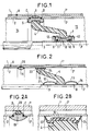
- references 1 and 1 ′ denote the steel envelopes of two adjacent compartments; the steel envelopes are welded at A.
- References 2 and 2 designate the inner aluminum envelopes, welded at B and C to a metal collar 5 comprising a groove in which is engaged the end of a closed insulating cone 4.
- a teflon band or ring 6, housed in a groove in the collar 5, ensures the spacing between the steel casing and the aluminum casing and allows the aluminum casing to slide into the steel casing during differential expansions or during mounting.
- the closed insulating cone 4 can be mounted on the collar 5 or inserted into the collar 5; in this last case, the necklace will be made in two parts.
- References 3 and 3 designate two conductor elements, preferably tubular, of aluminum or copper, welded in D and engaged in an axial opening of the insulating cone in which they can slide.
- Anti-corona rings 12 and 13 complete the device.
- the spaces 14 and 15 on either side of the insulating cone 4 are filled with gas, at the same pressure, because if the cone 4 is dustproof, it is not gas tight.
- FIG. 2 shows a variant in which the insulating cone 4 is no longer integral with the aluminum envelopes 2 and 2 '.
- the recess 11 is deleted.
- the cone is made integral with the conductors 3 and 3 'by welding at 26 and 27 of the anti-corona screens 12 and 13.
- the weld line D of the conductor elements is placed inside one of the anti-corona screens.
- the base of the cone 4 rests on the aluminum casing by means of a "Teflon" seal 16, provided with two skirts 23 and 24 ensuring the dust-tightness between the compartments on either side. of the cone.
- the aluminum envelope elements are welded at B and C to a metal ring 19, which carries in a groove a ring 20 in "teflon" ensuring the spacing between the steel envelope and the aluminum envelope and facilitating the sliding of these envelopes relative to each other during differential expansions.
- the assembly of the line is very simple and is carried out as follows: a collar 19 is welded at B to an element 2 of aluminum casing and a conductor element 3 is welded at 27 the anti-corona screen 12; a conductor element 3 'is welded in D to the conductor element 3; the insulating cone is then put in place, as well as the anti-corona screen 13 which is welded at 26 to the conductor element 3 '; an aluminum casing element is slid around the conductive element 3 'and it is pushed up to C against the ring 19; the element 2 'is welded to the ring 19 at C; the ring 21 prevents the injection of solder particles into the enclosure 14.
- a member 1 'of steel casing is slid around 2' then pushes it until it comes into abutment at A against the casing member steel 1; the envelope elements 1 and 1 ′ are welded at A; the operation is repeated several times (from 10 times to 15 times for example) until a section of line of desired length is obtained, for example 100 meters. Every 100 meters, it is necessary to provide a connection compartment between sections to ensure the free expansion of the various elements without deformation other than axial.
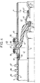
- FIG. 3 illustrates such a connection compartment 40 between the end of a section of line and the end of an adjacent section.
- the steel casing, the aluminum casing and the conductor of the left section 41 are designated by 1, 2 and 3 respectively, and by 1 ', 2' and 3 'the homologous elements of the right section 42.
- the conductor 3 is extended by a metal tube 48 carrying a contact-carrying sleeve 45; the conductor 3 is in electrical connection with the tube 48 by means of the sleeve 45 which is provided with a sliding electrical contact 46 and a dustproof seal 47.
- a space 44 is left between the end of the conductor 3 and the end of the tube 48 to allow them free expansion.
- the tube 48 is integral with a cone 43, held in place by a plate 49 of aluminum alloy and a crown 50.
- the plate 49 is clamped between the flanges 53 and 54 of two tubular aluminum portions 51 and 52; the end 57 opposite the flange 53 of the tubular portion 51 is engaged between the steel casing 1 and the aluminum casing 2.
- the free end of the latter can slide at the inside portion 57 which is provided with a sliding electrical contact 59 and with a dustproof seal 60.
- the tubular portion 51 is provided with a flange 51A for its fixing by bolts to a flange 55 at the end of the casing. steel 1.
- the end 58 opposite the flange 54 of the tubular portion 52 is engaged between the steel casing 1 'and the aluminum casing 2'; it is welded to the latter at 61. It is noted that the aluminum envelope 2, 2 'is fixed on one side and free on the other side of the section for its thermal expansion.
- the tubular portion 52 is provided with a flange 52A for its attachment to a flange 56 placed at the end of the steel casing 1 '.
- the tube 48 is provided with a bottom 71, so that the volumes 41A and 42A inside the sections 41 and 42 are perfectly sealed with respect to each other, this sealing being furthermore ensured by seals placed in the appropriate places.
- Gas filling valves 65, 68, drain valves 66, 69, sensors and possible outputs of optical fibers 67, 70 for example for the detection of internal arc, are mounted on the tubular portions 51 and 52.
- Figure 4 is an alternative embodiment of the compartment of Figure 3 and the common elements have been given the same reference numbers. The main difference lies in a greater simplification of the shape of the parts.
- the plate 49 is eliminated, the seal between the two compartments 41A and 42A being ensured by the bottom 71, this time located on the conductor 3, and by the cone 43, the base of which is directly enclosed by the flanges 57 and 58 provided with joints.
- valves 65, 66 and sensor outputs 67 are transferred to the steel casing 1.
- FIG 5 is an alternative embodiment of the compartment of Figure 3 and the elements common to these two figures have been given the same reference numbers.
- the bottom 71 of the tube 48 is deleted; inside the contact-carrying sleeve 45 is mounted a sealed metal bellows 72 connecting the conductive element 3 to the tube 48.
- the circulation can be a circulation of nitrogen which makes it possible to reduce the heating of the conductor during the period of overload or during the summer; the nitrogen pressure can be the same inside and outside the conductor (12 hectopascals for example).
- the heated gas can be cooled outside the cable, for example by ventilation, and reinjected into the conductor.
- demineralized water can be circulated.
- FIG. 6 is an alternative embodiment of the compartment of Figure 4 and the elements common to these figures have been given the same reference numbers.
- the bottom 71 has been removed and a metal or rubber bellows 72 has been placed fixed on the contact carrier 45 at the end of the conductor 3 by screws 72A and at the end 74 of the conductor 3 'by a collar 74A.
- the assembly is carried out as follows: the bellows are fixed on the contact carrier 45, the bellows is pulled by extending it beyond the contact carrier 45 and it is fixed on the end 74 of the conductor 3 'to the using collar 74A; the conductor 3 'is then pushed to the left to position the bellows in the space 76 delimited by the contact carrier 45.
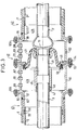
- connection 99 comprises two steel enclosures 100 and 101 and two aluminum enclosures 102 and 103.
- a first end of the steel casing 100 is secured, by bolts 106, to a flange 104 welded to the end of the steel casing 1 of the left sector.
- a first end of the aluminum casing 102 is fixed, by screws 102A, to an aluminum flange 114 secured to the aluminum casing 2 in the left sector.
- a first end of the steel casing 101 is fixed by screws 107 to a flange 105 welded to the end of the steel casing 1 'of the right sector.
- a first end of the aluminum casing 103 is provided with an electrical contact 103A cooperating with the end 116 of the casing 2 'of the right sector.
- the second ends of the steel envelopes 100 and 101 are provided with flanges enclosing the second curved ends of the aluminum envelopes 102 and 103.
- the tightening is ensured by means of screws 108.
- the cone 109 is fixed to the flange 114 by means of screws 115; at the end of the conductor 3 of the left sector is fixed a substantially tubular part 111 provided with a bottom 111A.
- a first end of a metal tube 110 is fixed by screw 112 to tube 111; the second end of the tube 110 carries a metal contact 113 cooperating with the conductor 3 'of the right sector.
- Reference 118 designates one or more valves for draining the gas.
- An anti-corona cover 120 provided with holes 119 for access to the screws 112, completes the equipment of the connection compartment 99.
- Disassembly is carried out as follows: after emptying the gas through the valves 118, the fasteners 106, 107, 108 and 102A are dismantled. The envelopes 100 and 102 are moved to the left and the envelope 101 to the right. The space thus released makes it possible to slide the envelope 103 to the left. Through the holes 119 which are now accessible, the screws 112 are removed and the tube 110 is pushed inside 3 '. The two sectors are thus separated.
- Figures 8A to 8C show the disassembly and replacement of a damaged compartment by an internal arc for example.
- Sensors make it possible to locate the damaged compartment with precision, for example by optical fibers.
- the space available between the 1.1 'and 2.2' envelopes is used to accommodate optical fibers used as sensors or as a medium for transmitting information along the electrical cable, and low energy low voltage electrical cables for the electronics supply.
- FIG. 8A shows the compartment M to be changed, that is to say approximately 10 meters assuming that the length between two cones is 8 meters for example.
- the new and complete compartment prepared in the factory will have a length of 10 meters for the 3 '' conductor, approximately 9.5 meters for the 2 '' aluminum enclosure and 9 meters for the 1 '' steel enclosure. It has a cone at each end.
- the points delimiting the new compartment in its future position are marked 82 ', 82' ', 84', 84 '', 86 ', 87.
- the repair is carried out as follows: - the damaged compartment is cut for example at 80 and 81. This makes it possible to first remove approximately 7 meters from the damaged compartment.
- the aluminum envelope portions 2 and 2 ′ are cut at 84 and 85 respectively. This allows the damaged cones to be removed and access to conductor 3 (or 3 '). The conductor 3 is then cut at 86 and the conductor 3 'at 87. This makes it possible to completely remove the damaged compartment.
- the distance between points 86 and 87 is 10 meters, equal to that of the new compartment to be installed.
- the new compartment is put in place (1 '', 2 '', 3 '', Figure 8B).
- the clearances between 82 and 82 ', 84 and 84' allow welding 86 to 86 '( Figure 8B).
- a small ring 88 can be used.
- a connecting piece 89 placed previously inside the aluminum envelope before the installation of the new compartment makes it possible to electrically link 2 and 2 '' by the welds 92 and 93 ( Figure 8C).
- Seals 90 and 91 prevent metal particles from entering the enclosure during welding at 92 and 93.
- a steel connecting tube 94 previously placed outside the tube 1 allows the compartment to be closed in leaktight manner by the welds at 95 and 96 (FIG. 8C).
Applications Claiming Priority (2)
| Application Number | Priority Date | Filing Date | Title |
|---|---|---|---|
| FR9315356 | 1993-12-21 | ||
| FR9315356A FR2714204B1 (fr) | 1993-12-21 | 1993-12-21 | Câble monophasé à isolation gazeuse pour le transport d'électricité. |
Publications (2)
| Publication Number | Publication Date |
|---|---|
| EP0660479A1 true EP0660479A1 (de) | 1995-06-28 |
| EP0660479B1 EP0660479B1 (de) | 1997-07-23 |
Family
ID=9454152
Family Applications (1)
| Application Number | Title | Priority Date | Filing Date |
|---|---|---|---|
| EP94402902A Expired - Lifetime EP0660479B1 (de) | 1993-12-21 | 1994-12-16 | Gasisoliertes einphasiges Stromkabel |
Country Status (7)
| Country | Link |
|---|---|
| US (1) | US5571990A (de) |
| EP (1) | EP0660479B1 (de) |
| AT (1) | ATE155935T1 (de) |
| CA (1) | CA2138632C (de) |
| DE (1) | DE69404435T2 (de) |
| ES (1) | ES2105577T3 (de) |
| FR (1) | FR2714204B1 (de) |
Cited By (11)
| Publication number | Priority date | Publication date | Assignee | Title |
|---|---|---|---|---|
| DE29515324U1 (de) * | 1995-09-13 | 1995-11-30 | Siemens Ag | Hochspannungsrohrleiter mit einem Isolierstoffkörper |
| DE29614714U1 (de) * | 1996-03-19 | 1997-07-17 | Siemens Ag | Verbindungsbaustein für eine gasisolierte Energieübertragungsanlage mit rohrförmigen Leitern |
| DE29614717U1 (de) * | 1996-03-19 | 1997-07-17 | Siemens Ag | Gasisolierte Energieübertragungsanlage mit in Abständen axial fixiertem Innenleiter |
| WO1997035371A1 (de) * | 1996-03-19 | 1997-09-25 | Siemens Aktiengesellschaft | Gasisolierte energieübertragungsanlage mit in abständen axial fixiertem innenleiter |
| DE19632398A1 (de) * | 1996-07-31 | 1998-02-05 | Siemens Ag | Gasisolierte Energieübertragungsanlage mit scheibenförmigen Stützisolatoren sowie Verfahren zum axialen Fixieren eines scheibenförmigen Stützisolators am rohrförmigen Außenleiter einer solchen Anlage |
| EP1225672A1 (de) * | 2001-01-22 | 2002-07-24 | Alstom | Gerät zur Kontrolle eines internen Fehlerlichtbogen für einen Anschlussmodul in einer gasisolierten Hochspannungsleitung |
| EP2595263A1 (de) * | 2011-11-16 | 2013-05-22 | Alstom Technology Ltd | Elektrisches Schaltgerät |
| CN103795017A (zh) * | 2014-03-03 | 2014-05-14 | 江苏神马电力股份有限公司 | 气体绝缘输电线路 |
| WO2017092787A1 (de) * | 2015-11-30 | 2017-06-08 | Siemens Aktiengesellschaft | Verfahren zur herstellung einer gasisolierten elektrischen energieübertragungsleitung |
| EP3553905A1 (de) * | 2009-07-17 | 2019-10-16 | Mitsubishi Electric Corporation | Gasisolierter bus |
| CN112217128A (zh) * | 2020-10-12 | 2021-01-12 | 华北电力大学 | 用于gis/gil中的金属微粒陷阱布置方法 |
Families Citing this family (16)
| Publication number | Priority date | Publication date | Assignee | Title |
|---|---|---|---|---|
| DE19502665C1 (de) * | 1995-01-20 | 1996-02-08 | Siemens Ag | Metallgekapselte Hochspannungsleitung mit einer Befestigungsvorrichtung für einen Isolierstoffstützer |
| DE19542595A1 (de) * | 1995-11-15 | 1997-05-22 | Asea Brown Boveri | Anlage zur Übertragung elektrischer Energie mit mindestens einem unterirdisch verlegten, hochspannungsführenden Stromleiter und Verfahren zur Herstellung einer solchen Anlage |
| FR2780565B1 (fr) * | 1998-06-25 | 2000-08-18 | Alsthom Gec | Ligne electrique a isolation gazeuse comportant deux barres conductrices reliees electriquement par une liaison souple |
| FR2797108B1 (fr) * | 1999-07-30 | 2004-01-09 | Alstom | Ligne electrique haute tension, a isolation gazeuse, module de raccordement entre troncons successifs constituant une telle ligne et procede de montage correspondant |
| FR2815185B1 (fr) * | 2000-10-09 | 2002-12-06 | Alstom | Ligne polyphasee a isolation gazeuse et module de raccordement pour un passage polyophase/monophase dans une telle ligne |
| DE102004056160A1 (de) * | 2004-11-18 | 2006-05-24 | Siemens Ag | Scheibenisolator |
| DE102008030997A1 (de) * | 2008-06-30 | 2009-12-31 | Siemens Aktiengesellschaft | Rohrleiteranordnung mit einem fluiddichten Kapselungsrohr |
| DE102008050488A1 (de) * | 2008-10-01 | 2010-04-08 | Siemens Aktiengesellschaft | Verfahren zur Verlegung eines elektrischen Leiters und Verlegevorrichtung |
| DE102008050489A1 (de) * | 2008-10-01 | 2010-04-08 | Siemens Aktiengesellschaft | Verfahren zur Reparatur eines gasisolierten Rohrleiters |
| KR20100091677A (ko) * | 2009-02-11 | 2010-08-19 | 엘에스전선 주식회사 | 도체 접속부의 통전 기능이 향상된 가스절연 송전선 |
| US8445777B2 (en) * | 2010-09-17 | 2013-05-21 | Mitsubishi Electric Power Products, Inc. | Gas insulated bus system configuration |
| RU2616589C2 (ru) * | 2012-01-09 | 2017-04-18 | Альстом Текнолоджи Лтд | Вилочный и розеточный изолированный чистым газом стеновой проходной изолятор для высокого напряжения постоянного тока и сверхвысокого напряжения |
| DE202014005301U1 (de) * | 2014-07-01 | 2014-07-17 | Abb Technology Ag | Kabelendverschluss zur Anbindung einer Schaltanlage an ein Hochspannungskabel |
| CN104092172B (zh) * | 2014-07-09 | 2017-07-07 | 江苏神马电力股份有限公司 | 气体绝缘输电线路 |
| CN104052011B (zh) * | 2014-07-09 | 2017-08-25 | 江苏神马电力股份有限公司 | 气体绝缘输电线路 |
| EP3961833B1 (de) * | 2019-04-25 | 2024-04-17 | Mitsubishi Electric Corporation | Gasisolierte stromschiene |
Citations (10)
| Publication number | Priority date | Publication date | Assignee | Title |
|---|---|---|---|---|
| DE7036895U (de) * | 1970-09-30 | 1970-12-23 | Siemens Ag | Druckgasisolierte hochspannungsleitung. |
| US3646245A (en) * | 1970-12-16 | 1972-02-29 | Gen Electric | Liquid-cooled bus containing a disconnecting link |
| FR2132646A1 (de) * | 1971-04-08 | 1972-11-24 | Siemens Ag | |
| DE2313749B1 (de) * | 1973-03-20 | 1974-08-29 | Allgemeine-Elektricitaets-Gesellschaft Aeg-Telefunken, 6000 Frankfurt | Schutzrohr, insbesondere für gasisolierte Hochspannungsrohrleitungen |
| FR2244240A1 (de) * | 1973-09-18 | 1975-04-11 | Siemens Ag | |
| DE2429158A1 (de) * | 1974-06-18 | 1976-01-08 | Bbc Brown Boveri & Cie | Vollgekapselte hochspannungsschaltanlage |
| EP0281323A2 (de) * | 1987-02-27 | 1988-09-07 | Asea Brown Boveri Inc. | Gasisolierte Übertragungsleitung mit einfacher Isolatoranordnung |
| FR2642578A1 (fr) * | 1989-01-27 | 1990-08-03 | Alsthom Gec | Ligne blindee |
| EP0423665A1 (de) * | 1989-10-16 | 1991-04-24 | Gec Alsthom Sa | Gekapselte elektrische Leitung und Verfahren zu seiner Herstellung |
| EP0573338A1 (de) * | 1992-06-03 | 1993-12-08 | Gec Alsthom T Et D Sa | Gasisolierte Dreiphasenleitung und dessen Herstellungsverfahren |
Family Cites Families (5)
| Publication number | Priority date | Publication date | Assignee | Title |
|---|---|---|---|---|
| JPS4791Y1 (de) * | 1969-10-16 | 1972-01-06 | ||
| US3792220A (en) * | 1972-09-19 | 1974-02-12 | Hitachi Ltd | Device for connecting extreme low temperature cable with normal temperature electric apparatus |
| US4161621A (en) * | 1977-06-29 | 1979-07-17 | Westinghouse Electric Corp. | Spacer mount for a gas insulated transmission line |
| JPS6048969B2 (ja) * | 1979-06-25 | 1985-10-30 | 三菱電機株式会社 | ガス絶縁送電路 |
| US4458100A (en) * | 1981-05-28 | 1984-07-03 | The United States Of America As Represented By The United States Department Of Energy | Gas insulated transmission line with insulators having field controlling recesses |
-
1993
- 1993-12-21 FR FR9315356A patent/FR2714204B1/fr not_active Expired - Fee Related
-
1994
- 1994-12-16 EP EP94402902A patent/EP0660479B1/de not_active Expired - Lifetime
- 1994-12-16 DE DE69404435T patent/DE69404435T2/de not_active Expired - Fee Related
- 1994-12-16 ES ES94402902T patent/ES2105577T3/es not_active Expired - Lifetime
- 1994-12-16 AT AT94402902T patent/ATE155935T1/de not_active IP Right Cessation
- 1994-12-20 CA CA002138632A patent/CA2138632C/fr not_active Expired - Fee Related
- 1994-12-20 US US08/360,008 patent/US5571990A/en not_active Expired - Fee Related
Patent Citations (10)
| Publication number | Priority date | Publication date | Assignee | Title |
|---|---|---|---|---|
| DE7036895U (de) * | 1970-09-30 | 1970-12-23 | Siemens Ag | Druckgasisolierte hochspannungsleitung. |
| US3646245A (en) * | 1970-12-16 | 1972-02-29 | Gen Electric | Liquid-cooled bus containing a disconnecting link |
| FR2132646A1 (de) * | 1971-04-08 | 1972-11-24 | Siemens Ag | |
| DE2313749B1 (de) * | 1973-03-20 | 1974-08-29 | Allgemeine-Elektricitaets-Gesellschaft Aeg-Telefunken, 6000 Frankfurt | Schutzrohr, insbesondere für gasisolierte Hochspannungsrohrleitungen |
| FR2244240A1 (de) * | 1973-09-18 | 1975-04-11 | Siemens Ag | |
| DE2429158A1 (de) * | 1974-06-18 | 1976-01-08 | Bbc Brown Boveri & Cie | Vollgekapselte hochspannungsschaltanlage |
| EP0281323A2 (de) * | 1987-02-27 | 1988-09-07 | Asea Brown Boveri Inc. | Gasisolierte Übertragungsleitung mit einfacher Isolatoranordnung |
| FR2642578A1 (fr) * | 1989-01-27 | 1990-08-03 | Alsthom Gec | Ligne blindee |
| EP0423665A1 (de) * | 1989-10-16 | 1991-04-24 | Gec Alsthom Sa | Gekapselte elektrische Leitung und Verfahren zu seiner Herstellung |
| EP0573338A1 (de) * | 1992-06-03 | 1993-12-08 | Gec Alsthom T Et D Sa | Gasisolierte Dreiphasenleitung und dessen Herstellungsverfahren |
Cited By (15)
| Publication number | Priority date | Publication date | Assignee | Title |
|---|---|---|---|---|
| DE29515324U1 (de) * | 1995-09-13 | 1995-11-30 | Siemens Ag | Hochspannungsrohrleiter mit einem Isolierstoffkörper |
| DE29614714U1 (de) * | 1996-03-19 | 1997-07-17 | Siemens Ag | Verbindungsbaustein für eine gasisolierte Energieübertragungsanlage mit rohrförmigen Leitern |
| DE29614717U1 (de) * | 1996-03-19 | 1997-07-17 | Siemens Ag | Gasisolierte Energieübertragungsanlage mit in Abständen axial fixiertem Innenleiter |
| WO1997035371A1 (de) * | 1996-03-19 | 1997-09-25 | Siemens Aktiengesellschaft | Gasisolierte energieübertragungsanlage mit in abständen axial fixiertem innenleiter |
| US6118068A (en) * | 1996-03-19 | 2000-09-12 | Siemens Aktiengesellschaft | Gas-insulated power transmission system with internal conductors fixed axially at intervals |
| DE19632398A1 (de) * | 1996-07-31 | 1998-02-05 | Siemens Ag | Gasisolierte Energieübertragungsanlage mit scheibenförmigen Stützisolatoren sowie Verfahren zum axialen Fixieren eines scheibenförmigen Stützisolators am rohrförmigen Außenleiter einer solchen Anlage |
| EP1225672A1 (de) * | 2001-01-22 | 2002-07-24 | Alstom | Gerät zur Kontrolle eines internen Fehlerlichtbogen für einen Anschlussmodul in einer gasisolierten Hochspannungsleitung |
| EP3553905A1 (de) * | 2009-07-17 | 2019-10-16 | Mitsubishi Electric Corporation | Gasisolierter bus |
| EP2595263A1 (de) * | 2011-11-16 | 2013-05-22 | Alstom Technology Ltd | Elektrisches Schaltgerät |
| WO2013072153A1 (de) * | 2011-11-16 | 2013-05-23 | Alstom Technology Ltd | Elektrisches schaltgerät |
| RU2603361C2 (ru) * | 2011-11-16 | 2016-11-27 | Альстом Текнолоджи Лтд | Электрический коммутационный аппарат |
| CN103795017A (zh) * | 2014-03-03 | 2014-05-14 | 江苏神马电力股份有限公司 | 气体绝缘输电线路 |
| WO2017092787A1 (de) * | 2015-11-30 | 2017-06-08 | Siemens Aktiengesellschaft | Verfahren zur herstellung einer gasisolierten elektrischen energieübertragungsleitung |
| CN112217128A (zh) * | 2020-10-12 | 2021-01-12 | 华北电力大学 | 用于gis/gil中的金属微粒陷阱布置方法 |
| CN112217128B (zh) * | 2020-10-12 | 2021-09-14 | 华北电力大学 | 用于gis/gil中的金属微粒陷阱布置方法 |
Also Published As
| Publication number | Publication date |
|---|---|
| FR2714204B1 (fr) | 1996-01-19 |
| ES2105577T3 (es) | 1997-10-16 |
| EP0660479B1 (de) | 1997-07-23 |
| ATE155935T1 (de) | 1997-08-15 |
| US5571990A (en) | 1996-11-05 |
| FR2714204A1 (fr) | 1995-06-23 |
| CA2138632C (fr) | 1999-08-17 |
| DE69404435T2 (de) | 1997-12-04 |
| DE69404435D1 (de) | 1997-09-04 |
| CA2138632A1 (fr) | 1995-06-22 |
Similar Documents
| Publication | Publication Date | Title |
|---|---|---|
| EP0660479B1 (de) | Gasisoliertes einphasiges Stromkabel | |
| CA2138634C (fr) | Ligne a haute tension a isolation gazeuse pour longue distance | |
| EP0543681B1 (de) | Mittelspannungslastschalter für innen oder aussen | |
| EP1681743B1 (de) | Verbindungsanordnung für die Abschirmungen von supraleitenden Kabeln | |
| EP0423665B1 (de) | Gekapselte elektrische Leitung und Verfahren zu seiner Herstellung | |
| EP2523291B1 (de) | Abzweigelement für eine Supraleiterkabeleinheit | |
| EP1624470B1 (de) | Dreiphasenstromwandler und elektrische Station mit einem solchen Stromwandler | |
| FR2692084A1 (fr) | Ligne blindée triphasée et son procédé de fabrication. | |
| CA2144671A1 (fr) | Dispositif de controle et de commande pour ligne de transport electrique blindee | |
| CH708026A1 (fr) | Procédé de fabrication d'un câble chauffant et câble chauffant réalisé selon ce procédé. | |
| FR2716521A1 (fr) | Raccord angulaire. | |
| FR2971101A1 (fr) | Systeme de transport de l'energie electrique sous enveloppe metallique a isolation mixte solide et gazeuse, pouvant etre enterre | |
| FR2642578A1 (fr) | Ligne blindee | |
| EP1195871B1 (de) | Mehrphasige druckgasisolierte Leitung und Anschlussmodule für ein-oder mehrphasige Durchführung in einer solchen Leitung | |
| EP0525583B1 (de) | Anordnung zum Verbinden zweier Kabel für hohe oder sehr hohe Spannung | |
| CA3176769A1 (fr) | Dispositif d'assemblage et d'evacuation des courants de fuite de deux portions d'enveloppes destinees a contenir un gaz sous pression | |
| BE353147A (fr) | Installation à rayons chi | |
| WO2012143472A1 (fr) | Ensemble electrique, haute ou moyenne tension, comprenant un disque isolant formant support de barre(s) conductrice(s) et une enveloppe metallique a paire de brides de retenue du disque | |
| EP1191654A1 (de) | Installationsrohr für einen elektrische Kabel und Verfahren zur Kontrolle der elektrischen Installation des installierten Kabels | |
| FR2555372A1 (fr) | Jonction souple de raccordement de deux cables d'energie a haute tension | |
| FR3097613B1 (fr) | Conduite sous-marine chauffante pour le transport de fluides et procédé d’assemblage d’une telle conduite | |
| EP0996210B1 (de) | Selbsttragender Kabelkopf | |
| BE540922A (de) | ||
| FR2515857A1 (fr) | Manchon pour cable a moyenne tension raccorde a un caisson metallique | |
| FR2509080A1 (fr) | Liaison electrique pour longues distances |
Legal Events
| Date | Code | Title | Description |
|---|---|---|---|
| PUAI | Public reference made under article 153(3) epc to a published international application that has entered the european phase |
Free format text: ORIGINAL CODE: 0009012 |
|
| AK | Designated contracting states |
Kind code of ref document: A1 Designated state(s): AT CH DE ES FR GB IT LI SE |
|
| 17P | Request for examination filed |
Effective date: 19951109 |
|
| GRAG | Despatch of communication of intention to grant |
Free format text: ORIGINAL CODE: EPIDOS AGRA |
|
| 17Q | First examination report despatched |
Effective date: 19961205 |
|
| GRAH | Despatch of communication of intention to grant a patent |
Free format text: ORIGINAL CODE: EPIDOS IGRA |
|
| GRAH | Despatch of communication of intention to grant a patent |
Free format text: ORIGINAL CODE: EPIDOS IGRA |
|
| GRAA | (expected) grant |
Free format text: ORIGINAL CODE: 0009210 |
|
| AK | Designated contracting states |
Kind code of ref document: B1 Designated state(s): AT CH DE ES FR GB IT LI SE |
|
| REF | Corresponds to: |
Ref document number: 155935 Country of ref document: AT Date of ref document: 19970815 Kind code of ref document: T |
|
| REG | Reference to a national code |
Ref country code: CH Ref legal event code: NV Representative=s name: GEC ALSTHOM SALES NETWORK SA Ref country code: CH Ref legal event code: EP |
|
| REF | Corresponds to: |
Ref document number: 69404435 Country of ref document: DE Date of ref document: 19970904 |
|
| REG | Reference to a national code |
Ref country code: ES Ref legal event code: FG2A Ref document number: 2105577 Country of ref document: ES Kind code of ref document: T3 |
|
| GBT | Gb: translation of ep patent filed (gb section 77(6)(a)/1977) |
Effective date: 19971023 |
|
| PLBE | No opposition filed within time limit |
Free format text: ORIGINAL CODE: 0009261 |
|
| STAA | Information on the status of an ep patent application or granted ep patent |
Free format text: STATUS: NO OPPOSITION FILED WITHIN TIME LIMIT |
|
| 26N | No opposition filed | ||
| REG | Reference to a national code |
Ref country code: GB Ref legal event code: IF02 |
|
| PGFP | Annual fee paid to national office [announced via postgrant information from national office to epo] |
Ref country code: GB Payment date: 20031126 Year of fee payment: 10 |
|
| PGFP | Annual fee paid to national office [announced via postgrant information from national office to epo] |
Ref country code: CH Payment date: 20031201 Year of fee payment: 10 Ref country code: AT Payment date: 20031201 Year of fee payment: 10 |
|
| PGFP | Annual fee paid to national office [announced via postgrant information from national office to epo] |
Ref country code: SE Payment date: 20031202 Year of fee payment: 10 |
|
| PGFP | Annual fee paid to national office [announced via postgrant information from national office to epo] |
Ref country code: DE Payment date: 20031205 Year of fee payment: 10 |
|
| PGFP | Annual fee paid to national office [announced via postgrant information from national office to epo] |
Ref country code: ES Payment date: 20031217 Year of fee payment: 10 |
|
| PG25 | Lapsed in a contracting state [announced via postgrant information from national office to epo] |
Ref country code: GB Free format text: LAPSE BECAUSE OF NON-PAYMENT OF DUE FEES Effective date: 20041216 Ref country code: AT Free format text: LAPSE BECAUSE OF NON-PAYMENT OF DUE FEES Effective date: 20041216 |
|
| PG25 | Lapsed in a contracting state [announced via postgrant information from national office to epo] |
Ref country code: SE Free format text: LAPSE BECAUSE OF NON-PAYMENT OF DUE FEES Effective date: 20041217 Ref country code: ES Free format text: LAPSE BECAUSE OF NON-PAYMENT OF DUE FEES Effective date: 20041217 |
|
| PG25 | Lapsed in a contracting state [announced via postgrant information from national office to epo] |
Ref country code: LI Free format text: LAPSE BECAUSE OF NON-PAYMENT OF DUE FEES Effective date: 20041231 Ref country code: CH Free format text: LAPSE BECAUSE OF NON-PAYMENT OF DUE FEES Effective date: 20041231 |
|
| REG | Reference to a national code |
Ref country code: FR Ref legal event code: CD Ref country code: FR Ref legal event code: CA |
|
| REG | Reference to a national code |
Ref country code: CH Ref legal event code: PFA Owner name: ALSTOM T & D S.A. Free format text: GEC ALSTHOM T ET D SA#38, AVENUE KLEBER#75016 PARIS (FR) -TRANSFER TO- ALSTOM T & D S.A.#25, AVENUE KLEBER#75116 PARIS (FR) |
|
| PG25 | Lapsed in a contracting state [announced via postgrant information from national office to epo] |
Ref country code: DE Free format text: LAPSE BECAUSE OF NON-PAYMENT OF DUE FEES Effective date: 20050701 |
|
| EUG | Se: european patent has lapsed | ||
| GBPC | Gb: european patent ceased through non-payment of renewal fee |
Effective date: 20041216 |
|
| REG | Reference to a national code |
Ref country code: CH Ref legal event code: PL |
|
| REG | Reference to a national code |
Ref country code: FR Ref legal event code: CD Ref country code: FR Ref legal event code: CA |
|
| PG25 | Lapsed in a contracting state [announced via postgrant information from national office to epo] |
Ref country code: IT Free format text: LAPSE BECAUSE OF NON-PAYMENT OF DUE FEES;WARNING: LAPSES OF ITALIAN PATENTS WITH EFFECTIVE DATE BEFORE 2007 MAY HAVE OCCURRED AT ANY TIME BEFORE 2007. THE CORRECT EFFECTIVE DATE MAY BE DIFFERENT FROM THE ONE RECORDED. Effective date: 20051216 |
|
| REG | Reference to a national code |
Ref country code: ES Ref legal event code: FD2A Effective date: 20041217 |
|
| PGFP | Annual fee paid to national office [announced via postgrant information from national office to epo] |
Ref country code: FR Payment date: 20130123 Year of fee payment: 19 |
|
| REG | Reference to a national code |
Ref country code: FR Ref legal event code: ST Effective date: 20140829 |
|
| PG25 | Lapsed in a contracting state [announced via postgrant information from national office to epo] |
Ref country code: FR Free format text: LAPSE BECAUSE OF NON-PAYMENT OF DUE FEES Effective date: 20131231 |