EP0660435A2 - Filtre électrique - Google Patents
Filtre électrique Download PDFInfo
- Publication number
- EP0660435A2 EP0660435A2 EP94309805A EP94309805A EP0660435A2 EP 0660435 A2 EP0660435 A2 EP 0660435A2 EP 94309805 A EP94309805 A EP 94309805A EP 94309805 A EP94309805 A EP 94309805A EP 0660435 A2 EP0660435 A2 EP 0660435A2
- Authority
- EP
- European Patent Office
- Prior art keywords
- resonator
- point
- coil
- filter
- conductive element
- Prior art date
- Legal status (The legal status is an assumption and is not a legal conclusion. Google has not performed a legal analysis and makes no representation as to the accuracy of the status listed.)
- Withdrawn
Links
Images


Classifications
-
- H—ELECTRICITY
- H01—ELECTRIC ELEMENTS
- H01P—WAVEGUIDES; RESONATORS, LINES, OR OTHER DEVICES OF THE WAVEGUIDE TYPE
- H01P1/00—Auxiliary devices
- H01P1/20—Frequency-selective devices, e.g. filters
- H01P1/201—Filters for transverse electromagnetic waves
- H01P1/205—Comb or interdigital filters; Cascaded coaxial cavities
- H01P1/2053—Comb or interdigital filters; Cascaded coaxial cavities the coaxial cavity resonators being disposed parall to each other
Definitions
- the present invention relates to a radio frequency filter the resonator of which is made up of a wire wound into a cylindrical coil comprising a number of turns, of a casing surrounding the coil, and of an insulating plate supporting the cylindrical coil from the inside, and in which the signal lead is connected to the resonator coil via the insulating plate.
- the resonator is a transmission line resonator, and it is made up of an approximately quarter-wave wire wound into a cylindrical coil disposed inside a grounded metal casing.
- the characteristic impedance of the resonator, and thereby its resonance frequency is determined by the physical dimensions of the cavity, the ratio of the diameter of the helix coil to the inner dimension of the casing, and the distance of the turns of the coil from each other, i.e. the so-called pitch, and the support structure possibly used for supporting the coil. For this reason, preparing a resonator to resonate at precisely a desired frequency requires an accurate and precise structure.
- a filter having desired properties can be constructed by series coupling of the resonators and by suitable arrangement of the coupling between them.
- the precision requirements imposed on their manufacture and assembly increase drastically, since even small dimensional variations in the cavity, the cylindrical coil and the support structure greatly effect the resonance frequency.
- the filter resonators must be matched with each other if a signal is introduced into the filter by physical coupling to its helix coil.
- a suitable impedance level must be found in the resonator, i.e. a physical connection point at which the impedance level from the connection point towards the resonator corresponds to the impedance level of the device to be coupled to it or of the adjacent resonator.
- the impedance level of the connection point is directly proportional to the distance of the connection point from the short-circuited end of the resonator, in which case a higher or lower impedance level can be selected by changing the connection point on the helix coil.
- This matching is called tapping, since the connection point forms a tap from the helix resonator.
- the tap point may be determined experimentally or be calculated by using the resonator's calculated or measured characteristic impedance, which in turn is proportional to the electrical length of the resonator. Often the tap point in a helix resonator is on its first turn.
- Tapping has conventionally been done by soldering, at the tap point, one end of a separate coil or wire to the wire forming the helix resonator.
- the reproduction fidelity of such a tapping method is inadequate for mass production.
- Inadequate tapping accuracy results to a need for adjusting the taps in the process of tuning the filters; this slows down the tuning and increases costs.
- the helix resonator 6 is disposed on a finger-like projection 3 of an insulating plate 1 in such a manner that the projection is within the resonator coil and supports the coil. At that end of the coil 6 which is towards the insulating plate 1, the beginning of the first turn is bent into a straight portion 2, the entire length of which is tightly against the surface of the insulating plate. The straight portion is called in the art the resonator leg. The end 7 of the portion 2 is in contact with the casing 5, being thereby short-circuited.
- the insulating plate has, at the base of the projection 3, a microstrip line 8 which is in contact with the rest of the resonator circuit or is part of a more extensive microstrip line pattern on the insulating plate.
- the microstrip line is parallel to the coil axis.
- the tap point is in this case the point at which the microstrip line 8 intersects with the straight portion 2 of the coil.
- the stripline and the straight portion are soldered to each other at this point.
- the tap point, and thereby the desired impedance level, is determined by moving the position of the microstrip line 8 in the lateral direction.
- This method has the disadvantage that the changing of the impedance level of the tap point requires a large number of insulating plates different with respect to the lateral position of the microstrip line. This is a cost-increasing factor.
- Another disadvantage is that fine adjustment of the tap point is impossible, since the leg must come against the insulating plate. In practice the leg being against the insulating plate is not a very good solution, since the leg against a dissipative plate will increase resonator dissipation.
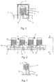
- FIG. 2 shows a part within the casing of a four-circuit filter, the part comprising four discrete helix resonators - separate reference is made to resonators 6 and 7 - each of which is disposed around a finger-like projection 3 of the circuit board 1.
- the term used in the art is 'comb structure'.
- the tap point is here at the first turn of the coil, but it may just as well be higher.
- resonator 7 in Figure 2, in which the tap point 22 is at the second turn of the coil.
- the stripline extends somewhat upwards in the finger-like projection and ends at the projection edge, at which the soldering takes place to the resonator turn which is at that point.
- the tap point may thus be at any resonator turn, and there may be a number of tap points.
- the straight leg 2 of the resonator has, in a manner different from the leg in Figure 1, been bent to be parallel to the resonator axis, running at a distance from the insulating plate, and at the assembling stage its other end connects to the bottom plate 31, Figure 3, of the casing, and is thereby grounded if the plate is of metal.
- the bottom plate of the casing may also be made up of a circuit board of the radio device, at least one surface of the circuit board in the filter area being metallized throughout, in which case the tip of the leg is connected to the metallized surface.
- FIG. 4 depicts a completed filter according to the state of the art, the filter casing 41 being shown partly as a cutaway so that the resonator is clearly visible.
- This filter has, between the circuits, partition walls, of which walls 42 and 43 are visible, which may have a coupling aperture (not shown in the figure) through which the circuit can be coupled by an electromagnetic field to the adjacent circuit.
- the partition wall has no significance in terms of the invention, nor does the manner in which the insulating plate supporting the resonators is attached to the casing walls.
- the casing 41 is most commonly an aluminum casing manufactured by extrusion, and the bottom plate 44 may be a metal plate or a circuit board one surface of which is metallized.
- the tap points 21 and 22 of the helix resonators 6 and 7 which are visible are indicated with black dots, and at this tap point the resonator connects to a stripline circuit (not shown in the figure) made in the lower section 1A and fingers 3 of the insulating plate.
- the tips 12 and 13 of the legs 2 and 2' are soldered to the bottom plate 44 if the plate or its surface is of metal, or they are electrically connected to a metal foil on the opposite side of the bottom plate if the bottom plate is a circuit board.
- a filter comprising: a conductive element grounded at a point; and a wound resonator adapted to be coupled at one end to any one of a range of positions on the conductive element each having a respective impedance to ground and to a circuit at a tapping point distance from the one end.
- a filter comprising: at least one resonator formed from a wire wound into a cylindrical coil and which has, adjoining a first turn a straight portion substantially parallel to the axis of the coil; an insulating plate that supports the coil from within; a circuit for coupling to the resonator at a tapping point where the circuit and cylindrical coil are in contact; and a lead disposed on a bottom plate transverse to the axis of the coil, the lead being short-circuited at one end and open at the other positioned such that the tip of the straight portion contacts the lead.
- the invention thus provides a filter which enables the tap impedance to remain substantially unchanged despite slight variation in the rotational position of the coil.
- the variation in the tap impedance during manufacture can be maintained at a very low level.
- the bottom plate may be formed from an insulating material and the leads may be a microstrip line on the surface of the bottom plate which preferably, although not necessarily, follows a circle arc.
- the radius of curvature of the stripline may be the same as the distance of the tip of the resonator leg from the resonator axis.
- the width and thickness of the stripline can be selected freely, but its length is preferably less than a semi-circle arc, and it is located on the bottom plate on that side adjacent to the insulating plate supporting the resonators on which the resonator leg is located.
- the other end of the stripline may be electrically connected to a wall of the filter casing or to the continuous metal foil on the opposite side of the insulating plate, in which case it is thereby grounded.
- the partition wall has no significance in terms of the invention, nor does the manner in which the insulating plate supporting the resonators is attached to the casing wall.
- the tip of the leg When the helix coil is disposed on a finger-like projection of the insulating plate serving as the supporting structure, and is pressed into its final position, the tip of the leg will come into contact with the stripline.
- the physical length from the tap point to the grounding point is the length of the resonator coil from the tap point to the tip of the leg plus the distance from the contact point between the tip and the stripline to the grounding point of the other end of the stripline.
- This desired physical length has been calculated in advance according to the desired tap impedance.
- the invention thus provides a structure by which a change in the impedance Z res,low which change is due to productional variation in the placement of the helix coil on the finger of the insulating plate, is automatically compensated for by a change of corresponding magnitude but of opposite sign in the impedance Z stripline .
- the electrical length of the stripline can be made adjustable, by for example changing the short-circuiting point. This may be achieved by grinding off parts of the stripline. In this case its electrical (and physical) length can be increased by grinding, whereupon the tap impedance will increase even if the contact point of the tip of the resonator leg does not change.
- a part of the stripline may also be replaced with a discrete inductive means such as a coil.
- the wire is placed at a distance from the plate surface, parallel to it.
- One end of the wire is bent and electrically connected, for example by soldering, to the plate.
- the other end may be attached to the plate via an insulating piece.
- the wire may be configured in similar ways to the stripline.
- FIG. 5 depicts a filter which has some structural similarities with the prior art filter of Figure 4. Like parts are designated with like reference numerals.
- On the inner surface of the filter's insulating bottom plate 44 striplines to which the resonator legs are to be tapped are provided.
- Each of the resonators 6, 7 has a respective stripline 51, 52 on the bottom plate.
- These striplines preferably follow a circle arc, more precisely the circle arc plotted by the tip 12, 13 of a resonator leg 2, 2' when the resonator rotates about its longitudinal axis, the resonator being disposed on the finger-like projection 3.
- the stripline is, of course, on the same side of the bottom plate divided into two halves by insulating plate 1A as is the resonator leg.
- each of the striplines 51, 52 is short-circuited.
- the short-circuited end is indicated in Figure 5 by reference E.
- the short-circuiting can be effected by connecting the end E of the stripline directly through the circuit board to the metallization. Grounding can also be effected by connecting the stripline end inside the bottom plate to the metallic wall of the casing, either to a side wall or a partition wall possibly between the circuits.
- the tap impedance Z tap for example in resonator 6, has at the planning stage been calculated so that it corresponds to a physical distance from the tap point 21 to the tip 12 of the leg 2 plus the distance from the contact point between the tip 12 of the leg 2 and the stripline 51 in the bottom plate to the short-circuited end E of the strip-line.
- the helix coil is placed on the projection 3 of the insulating plate.
- the topmost line segment of Figure 6 shows the physical length of the helix coil.
- the tap point for example point 21 in Figure 5. Since the tapping is done to a stripline on a circuit board, this point is a fixed point with respect to the helix coil.
- the distance from this point along the resonator to the tip of its leg is 11, and this distance corresponds to certain impedance Z res, low . This distance changes according to how the resonator coil rotates about its axis during installation.
- the distance from the contact point between the tip 12 of the resonator leg and the stripline along the stripline to its short-circuited end is 12, and this distance is corresponded to by an impedance Z stripline . determined by the dimensions of the stripline.
- the stripline is fixed, with respect to the resonator coil, and therefore, when the resonator coil rotates, the contact point slides on the stripline.
- the impedance Z stripline changing correspondingly.
- the resonator coil 6 When, for example, the resonator coil 6 is being disposed on the projection 3, it may happen that it rotates from the set position so that the leg 2 in Figure 5 turns to the left. According to Figure 6 this means that distance 11 decreases. But distance 12 increases correspondingly. The changes in the distances almost completely cancel each other, and so the total distance sum 11 + 12 remains unchanged, from which it follows that the tap impedance Z tap will not change. Respectively, if the leg 2 in Figure 5 turns to the right at the installation stage, 11 increases but 12 decreases by the corresponding amount, and so the total impedance Z tap will remain unchanged.
- the resonator leg 2 should not be very close to the insulating plate 1A owing to the microstrip lines on it. If the leg is very close, during reflow soldering the paste may rise up between the leg and the insulating plate and short-circuit the leg to the lead patterns on the insulating plate. In practice the leg may be located in a sector perpendicular to the insulating plate 1A, the sector being 45 degrees. This means that the open end of the stripline on the bottom plate need not extend outside this sector.
- the length of the stripline on the bottom plate may be made adjustable.
- Figure 7 depicts a plan view of the stripline, tabs with one end grounded have been made in the stripline. The grounded end is indicated by reference E.
- E By cutting groundings from the direction of the resonator coil the length of the stripline can be increased and thus the tap impedance be increased, should this be necessary in tuning up a completed product.
- tabs it is possible to use through coppered holes disposed along the length of the stripline, the holes connecting the stripline to the metal foil on the opposite side of the plate. By drilling holes open the electric contact in the area of the hole can be disconnected, and thus the electrical length of the stripline can be increased.
- the various possibilities are known to the man skilled in the art.
- a stripline has been used. While remaining within the scope of protection of the invention it is also possible to use other methods of implementation.
- the stripline it is possible to use a rigid metal wire which is on the surface of the insulating plate in close contact with the plate.
- the wire may also be at some distance from the surface of the plate and the ends of the wire be attached to the plate and one end be in addition, short-circuited.
- Figure 8 If the bottom plate 84 of the filter is a metal plate, the wire 82 is a usable solution. In this case, one end of the wire may be electrically connected directly to the bottom plate, the grounded ends being indicated by E, and the other end may be attached to it with insulation. In this case the resonator leg 2 will not extend all the way to the bottom plate 84; it touches the wire 82, to which it is electrically connected after the soldering process.
Applications Claiming Priority (2)
| Application Number | Priority Date | Filing Date | Title |
|---|---|---|---|
| FI935841A FI94914C (fi) | 1993-12-23 | 1993-12-23 | Kamparakenteinen helix-suodatin |
| FI935841 | 1993-12-23 |
Publications (2)
| Publication Number | Publication Date |
|---|---|
| EP0660435A2 true EP0660435A2 (fr) | 1995-06-28 |
| EP0660435A3 EP0660435A3 (fr) | 1996-06-05 |
Family
ID=8539178
Family Applications (1)
| Application Number | Title | Priority Date | Filing Date |
|---|---|---|---|
| EP94309805A Withdrawn EP0660435A3 (fr) | 1993-12-23 | 1994-12-23 | Filtre électrique. |
Country Status (6)
| Country | Link |
|---|---|
| US (1) | US5585771A (fr) |
| EP (1) | EP0660435A3 (fr) |
| JP (1) | JPH07221515A (fr) |
| AU (1) | AU8152594A (fr) |
| CA (1) | CA2138678A1 (fr) |
| FI (1) | FI94914C (fr) |
Cited By (2)
| Publication number | Priority date | Publication date | Assignee | Title |
|---|---|---|---|---|
| WO1999056340A1 (fr) * | 1998-04-24 | 1999-11-04 | Nokia Networks Oy | Ensemble resonateur |
| EP2731192A1 (fr) * | 2012-11-08 | 2014-05-14 | Angel Iglesias, S.A. | Filtre coupe-bande pour interférence de signaux |
Families Citing this family (39)
| Publication number | Priority date | Publication date | Assignee | Title |
|---|---|---|---|---|
| FI110391B (fi) * | 1995-11-08 | 2003-01-15 | Solitra Oy | Kotelorakenteinen suodatin |
| WO2006000650A1 (fr) | 2004-06-28 | 2006-01-05 | Pulse Finland Oy | Composant antenne |
| FI20055420A0 (fi) | 2005-07-25 | 2005-07-25 | Lk Products Oy | Säädettävä monikaista antenni |
| FI119009B (fi) | 2005-10-03 | 2008-06-13 | Pulse Finland Oy | Monikaistainen antennijärjestelmä |
| FI118782B (fi) | 2005-10-14 | 2008-03-14 | Pulse Finland Oy | Säädettävä antenni |
| FI119577B (fi) * | 2005-11-24 | 2008-12-31 | Pulse Finland Oy | Monikaistainen antennikomponentti |
| US8618990B2 (en) | 2011-04-13 | 2013-12-31 | Pulse Finland Oy | Wideband antenna and methods |
| US10211538B2 (en) | 2006-12-28 | 2019-02-19 | Pulse Finland Oy | Directional antenna apparatus and methods |
| FI20075269A0 (fi) | 2007-04-19 | 2007-04-19 | Pulse Finland Oy | Menetelmä ja järjestely antennin sovittamiseksi |
| FI120427B (fi) | 2007-08-30 | 2009-10-15 | Pulse Finland Oy | Säädettävä monikaista-antenni |
| US9149939B2 (en) | 2009-03-06 | 2015-10-06 | Pall Life Sciences Belgium | Disposable isolator comprising means for filling containers |
| FI20096134A0 (fi) | 2009-11-03 | 2009-11-03 | Pulse Finland Oy | Säädettävä antenni |
| FI20096251A0 (sv) | 2009-11-27 | 2009-11-27 | Pulse Finland Oy | MIMO-antenn |
| US8847833B2 (en) | 2009-12-29 | 2014-09-30 | Pulse Finland Oy | Loop resonator apparatus and methods for enhanced field control |
| FI20105158A (fi) | 2010-02-18 | 2011-08-19 | Pulse Finland Oy | Kuorisäteilijällä varustettu antenni |
| US9406998B2 (en) | 2010-04-21 | 2016-08-02 | Pulse Finland Oy | Distributed multiband antenna and methods |
| FI20115072A0 (fi) | 2011-01-25 | 2011-01-25 | Pulse Finland Oy | Moniresonanssiantenni, -antennimoduuli ja radiolaite |
| US9673507B2 (en) | 2011-02-11 | 2017-06-06 | Pulse Finland Oy | Chassis-excited antenna apparatus and methods |
| US8648752B2 (en) | 2011-02-11 | 2014-02-11 | Pulse Finland Oy | Chassis-excited antenna apparatus and methods |
| US8866689B2 (en) | 2011-07-07 | 2014-10-21 | Pulse Finland Oy | Multi-band antenna and methods for long term evolution wireless system |
| US9450291B2 (en) | 2011-07-25 | 2016-09-20 | Pulse Finland Oy | Multiband slot loop antenna apparatus and methods |
| US9123990B2 (en) | 2011-10-07 | 2015-09-01 | Pulse Finland Oy | Multi-feed antenna apparatus and methods |
| US9531058B2 (en) | 2011-12-20 | 2016-12-27 | Pulse Finland Oy | Loosely-coupled radio antenna apparatus and methods |
| US9484619B2 (en) | 2011-12-21 | 2016-11-01 | Pulse Finland Oy | Switchable diversity antenna apparatus and methods |
| US20130194766A1 (en) * | 2012-01-31 | 2013-08-01 | U.D.Electronic Corp. | Signal filtering mounting sctructure |
| US8988296B2 (en) | 2012-04-04 | 2015-03-24 | Pulse Finland Oy | Compact polarized antenna and methods |
| US9979078B2 (en) | 2012-10-25 | 2018-05-22 | Pulse Finland Oy | Modular cell antenna apparatus and methods |
| US10069209B2 (en) | 2012-11-06 | 2018-09-04 | Pulse Finland Oy | Capacitively coupled antenna apparatus and methods |
| US10079428B2 (en) | 2013-03-11 | 2018-09-18 | Pulse Finland Oy | Coupled antenna structure and methods |
| US9647338B2 (en) | 2013-03-11 | 2017-05-09 | Pulse Finland Oy | Coupled antenna structure and methods |
| US9634383B2 (en) | 2013-06-26 | 2017-04-25 | Pulse Finland Oy | Galvanically separated non-interacting antenna sector apparatus and methods |
| US10858132B2 (en) | 2013-10-18 | 2020-12-08 | Pall Life Sciences Belgium Bvba | Disposable production line for filling and finishing a product |
| US9680212B2 (en) | 2013-11-20 | 2017-06-13 | Pulse Finland Oy | Capacitive grounding methods and apparatus for mobile devices |
| US9590308B2 (en) | 2013-12-03 | 2017-03-07 | Pulse Electronics, Inc. | Reduced surface area antenna apparatus and mobile communications devices incorporating the same |
| US9350081B2 (en) | 2014-01-14 | 2016-05-24 | Pulse Finland Oy | Switchable multi-radiator high band antenna apparatus |
| US9948002B2 (en) | 2014-08-26 | 2018-04-17 | Pulse Finland Oy | Antenna apparatus with an integrated proximity sensor and methods |
| US9973228B2 (en) | 2014-08-26 | 2018-05-15 | Pulse Finland Oy | Antenna apparatus with an integrated proximity sensor and methods |
| US9722308B2 (en) | 2014-08-28 | 2017-08-01 | Pulse Finland Oy | Low passive intermodulation distributed antenna system for multiple-input multiple-output systems and methods of use |
| US9906260B2 (en) | 2015-07-30 | 2018-02-27 | Pulse Finland Oy | Sensor-based closed loop antenna swapping apparatus and methods |
Citations (3)
| Publication number | Priority date | Publication date | Assignee | Title |
|---|---|---|---|---|
| FR1049282A (fr) * | 1951-03-09 | 1953-12-29 | Materiel Telephonique | Circuit résonnant applicable plus particulièrement aux courants à très haute fréquence |
| US4682131A (en) * | 1985-06-07 | 1987-07-21 | Motorola Inc. | High-Q RF filter with printed circuit board mounting temperature compensated and impedance matched helical resonators |
| WO1989005046A1 (fr) * | 1987-11-20 | 1989-06-01 | Lk-Products Oy | Resonateur avec ligne de transmission |
Family Cites Families (3)
| Publication number | Priority date | Publication date | Assignee | Title |
|---|---|---|---|---|
| US4342969A (en) * | 1980-10-06 | 1982-08-03 | General Electric Company | Means for matching impedances between a helical resonator and a circuit connected thereto |
| FI80542C (fi) * | 1988-10-27 | 1990-06-11 | Lk Products Oy | Resonatorkonstruktion. |
| US5432489A (en) * | 1992-03-09 | 1995-07-11 | Lk-Products Oy | Filter with strip lines |
-
1993
- 1993-12-23 FI FI935841A patent/FI94914C/fi not_active IP Right Cessation
-
1994
- 1994-12-19 AU AU81525/94A patent/AU8152594A/en not_active Abandoned
- 1994-12-21 CA CA002138678A patent/CA2138678A1/fr not_active Abandoned
- 1994-12-22 JP JP6320821A patent/JPH07221515A/ja active Pending
- 1994-12-23 US US08/363,234 patent/US5585771A/en not_active Expired - Fee Related
- 1994-12-23 EP EP94309805A patent/EP0660435A3/fr not_active Withdrawn
Patent Citations (3)
| Publication number | Priority date | Publication date | Assignee | Title |
|---|---|---|---|---|
| FR1049282A (fr) * | 1951-03-09 | 1953-12-29 | Materiel Telephonique | Circuit résonnant applicable plus particulièrement aux courants à très haute fréquence |
| US4682131A (en) * | 1985-06-07 | 1987-07-21 | Motorola Inc. | High-Q RF filter with printed circuit board mounting temperature compensated and impedance matched helical resonators |
| WO1989005046A1 (fr) * | 1987-11-20 | 1989-06-01 | Lk-Products Oy | Resonateur avec ligne de transmission |
Cited By (3)
| Publication number | Priority date | Publication date | Assignee | Title |
|---|---|---|---|---|
| WO1999056340A1 (fr) * | 1998-04-24 | 1999-11-04 | Nokia Networks Oy | Ensemble resonateur |
| US6456175B1 (en) | 1998-04-24 | 2002-09-24 | Nokia Networks Oy | Helical and coaxial resonator combination |
| EP2731192A1 (fr) * | 2012-11-08 | 2014-05-14 | Angel Iglesias, S.A. | Filtre coupe-bande pour interférence de signaux |
Also Published As
| Publication number | Publication date |
|---|---|
| FI94914B (fi) | 1995-07-31 |
| FI935841A0 (fi) | 1993-12-23 |
| US5585771A (en) | 1996-12-17 |
| JPH07221515A (ja) | 1995-08-18 |
| CA2138678A1 (fr) | 1995-06-24 |
| AU8152594A (en) | 1995-06-29 |
| EP0660435A3 (fr) | 1996-06-05 |
| FI94914C (fi) | 1995-11-10 |
Similar Documents
| Publication | Publication Date | Title |
|---|---|---|
| US5585771A (en) | Helical resonator filter including short circuit stub tuning | |
| US4977383A (en) | Resonator structure | |
| EP0706230B1 (fr) | Filtre à fréquence radio avec résonateurs hélicoidaux | |
| FI91116C (fi) | Helix-resonaattori | |
| FI78198C (fi) | Oeverfoeringsledningsresonator. | |
| FI87405C (fi) | Hoegfrekvensfilter | |
| US6400238B1 (en) | Dielectric filter having side surface indentation | |
| WO1995024743A1 (fr) | Ligne de transmission et sa conception | |
| EP0646986A1 (fr) | Antenne accordable à plaquette à circuit imprimé | |
| EP0508733A2 (fr) | Filtre céramique ajustable | |
| US5028896A (en) | Stripline circuit | |
| US4675623A (en) | Adjustable cavity to microstripline transition | |
| CA1303167C (fr) | Connecteur electrique | |
| US6529091B2 (en) | Absorptive circuit element, absorptive low-pass filter and manufacturing method of the filter | |
| KR100314085B1 (ko) | 유전체 필터 | |
| FI87406C (fi) | Bandpassfilter | |
| EP0797267A2 (fr) | Filtre à fréquence radio et méthode d'ajustement de la réponse en fréquence | |
| JPH03240302A (ja) | 誘電体フィルタの入出力結合構造 | |
| JPH0354883B2 (fr) |
Legal Events
| Date | Code | Title | Description |
|---|---|---|---|
| PUAI | Public reference made under article 153(3) epc to a published international application that has entered the european phase |
Free format text: ORIGINAL CODE: 0009012 |
|
| AK | Designated contracting states |
Kind code of ref document: A2 Designated state(s): CH DE DK FR GB IT LI SE |
|
| PUAL | Search report despatched |
Free format text: ORIGINAL CODE: 0009013 |
|
| AK | Designated contracting states |
Kind code of ref document: A3 Designated state(s): CH DE DK FR GB IT LI SE |
|
| STAA | Information on the status of an ep patent application or granted ep patent |
Free format text: STATUS: THE APPLICATION IS DEEMED TO BE WITHDRAWN |
|
| 18D | Application deemed to be withdrawn |
Effective date: 19961206 |