EP0660209B2 - Méthode et dispositif pour la transmission en série de données entre un appareil de mesure de position et une unité de traitement de données - Google Patents
Méthode et dispositif pour la transmission en série de données entre un appareil de mesure de position et une unité de traitement de données Download PDFInfo
- Publication number
- EP0660209B2 EP0660209B2 EP94119466A EP94119466A EP0660209B2 EP 0660209 B2 EP0660209 B2 EP 0660209B2 EP 94119466 A EP94119466 A EP 94119466A EP 94119466 A EP94119466 A EP 94119466A EP 0660209 B2 EP0660209 B2 EP 0660209B2
- Authority
- EP
- European Patent Office
- Prior art keywords
- processing unit
- measuring device
- clock
- transmitted
- position measuring
- Prior art date
- Legal status (The legal status is an assumption and is not a legal conclusion. Google has not performed a legal analysis and makes no representation as to the accuracy of the status listed.)
- Expired - Lifetime
Links
- 238000012545 processing Methods 0.000 title claims abstract description 84
- 230000005540 biological transmission Effects 0.000 title claims abstract description 60
- 238000000034 method Methods 0.000 title claims abstract description 15
- 230000015654 memory Effects 0.000 claims abstract description 50
- 238000005259 measurement Methods 0.000 claims description 30
- 238000001208 nuclear magnetic resonance pulse sequence Methods 0.000 claims description 8
- 230000015572 biosynthetic process Effects 0.000 claims description 5
- 230000001360 synchronised effect Effects 0.000 claims description 5
- 230000001419 dependent effect Effects 0.000 claims description 4
- 230000006870 function Effects 0.000 claims description 2
- 230000001960 triggered effect Effects 0.000 claims 3
- 230000004044 response Effects 0.000 claims 2
- 238000012937 correction Methods 0.000 description 9
- 230000002457 bidirectional effect Effects 0.000 description 4
- 238000010586 diagram Methods 0.000 description 3
- 125000004122 cyclic group Chemical group 0.000 description 2
- 238000011156 evaluation Methods 0.000 description 2
- 238000012544 monitoring process Methods 0.000 description 2
- 238000012360 testing method Methods 0.000 description 2
- 230000006978 adaptation Effects 0.000 description 1
- 230000006399 behavior Effects 0.000 description 1
- 239000000969 carrier Substances 0.000 description 1
- 238000012423 maintenance Methods 0.000 description 1
- 230000007257 malfunction Effects 0.000 description 1
- 238000004519 manufacturing process Methods 0.000 description 1
- 230000000630 rising effect Effects 0.000 description 1
Images


Classifications
-
- G—PHYSICS
- G05—CONTROLLING; REGULATING
- G05B—CONTROL OR REGULATING SYSTEMS IN GENERAL; FUNCTIONAL ELEMENTS OF SUCH SYSTEMS; MONITORING OR TESTING ARRANGEMENTS FOR SUCH SYSTEMS OR ELEMENTS
- G05B19/00—Programme-control systems
- G05B19/02—Programme-control systems electric
- G05B19/18—Numerical control [NC], i.e. automatically operating machines, in particular machine tools, e.g. in a manufacturing environment, so as to execute positioning, movement or co-ordinated operations by means of programme data in numerical form
- G05B19/414—Structure of the control system, e.g. common controller or multiprocessor systems, interface to servo, programmable interface controller
- G05B19/4142—Structure of the control system, e.g. common controller or multiprocessor systems, interface to servo, programmable interface controller characterised by the use of a microprocessor
-
- G—PHYSICS
- G05—CONTROLLING; REGULATING
- G05B—CONTROL OR REGULATING SYSTEMS IN GENERAL; FUNCTIONAL ELEMENTS OF SUCH SYSTEMS; MONITORING OR TESTING ARRANGEMENTS FOR SUCH SYSTEMS OR ELEMENTS
- G05B2219/00—Program-control systems
- G05B2219/30—Nc systems
- G05B2219/33—Director till display
- G05B2219/33234—Detect bad data transfer
-
- G—PHYSICS
- G05—CONTROLLING; REGULATING
- G05B—CONTROL OR REGULATING SYSTEMS IN GENERAL; FUNCTIONAL ELEMENTS OF SUCH SYSTEMS; MONITORING OR TESTING ARRANGEMENTS FOR SUCH SYSTEMS OR ELEMENTS
- G05B2219/00—Program-control systems
- G05B2219/30—Nc systems
- G05B2219/33—Director till display
- G05B2219/33254—Serial position feedback, serial to parallel conversion and reverse
-
- G—PHYSICS
- G05—CONTROLLING; REGULATING
- G05B—CONTROL OR REGULATING SYSTEMS IN GENERAL; FUNCTIONAL ELEMENTS OF SUCH SYSTEMS; MONITORING OR TESTING ARRANGEMENTS FOR SUCH SYSTEMS OR ELEMENTS
- G05B2219/00—Program-control systems
- G05B2219/30—Nc systems
- G05B2219/34—Director, elements to supervisory
- G05B2219/34012—Smart, intelligent I-O coprocessor, programmable sensor interface
-
- G—PHYSICS
- G05—CONTROLLING; REGULATING
- G05B—CONTROL OR REGULATING SYSTEMS IN GENERAL; FUNCTIONAL ELEMENTS OF SUCH SYSTEMS; MONITORING OR TESTING ARRANGEMENTS FOR SUCH SYSTEMS OR ELEMENTS
- G05B2219/00—Program-control systems
- G05B2219/30—Nc systems
- G05B2219/37—Measurements
- G05B2219/37154—Encoder and absolute position counter
-
- G—PHYSICS
- G05—CONTROLLING; REGULATING
- G05B—CONTROL OR REGULATING SYSTEMS IN GENERAL; FUNCTIONAL ELEMENTS OF SUCH SYSTEMS; MONITORING OR TESTING ARRANGEMENTS FOR SUCH SYSTEMS OR ELEMENTS
- G05B2219/00—Program-control systems
- G05B2219/30—Nc systems
- G05B2219/37—Measurements
- G05B2219/37494—Intelligent sensor, data handling incorporated in sensor
-
- H—ELECTRICITY
- H04—ELECTRIC COMMUNICATION TECHNIQUE
- H04L—TRANSMISSION OF DIGITAL INFORMATION, e.g. TELEGRAPHIC COMMUNICATION
- H04L7/00—Arrangements for synchronising receiver with transmitter
- H04L7/0008—Synchronisation information channels, e.g. clock distribution lines
Definitions
- the invention relates to a device and a method for serial data transmission between a position measuring device and a processing unit, in particular an NC controller.
- the processing unit must be adapted by the user to the specific parameters of the position measuring device. For example, the number of clocks required to complete the transmission of a position measurement value depends on the resolution of the position measurement device. So far, the processing unit has specified a fixed number of pulses (for example, 13). If a position measuring device with low resolution (for example 5 bits) is used, then the 13 clocks are still used for the measured value transmission. It can be seen that this unnecessary idle time is consumed.
- the invention is therefore based on the object to optimize the adaptation of the processing unit to specific parameters of the position measuring and minimize the cost of transmission lines between the position and the processing unit.
- the particular advantages of the invention are that the specific parameters of the position measuring device can be taken over automatically by the processing unit, wherein the same lines are used to transmit these parameters, which are already present for the measured value transmission. Furthermore, a secure transmission is guaranteed.
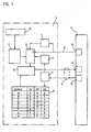
- the reference numeral 1 designates an angle measuring device which transmits the respective absolute position as binary data word to a processing unit 4.
- a processing unit 4 By known photoelectrical reduction of one code disk or several code disks (multiturn) connected via reduction gears generated by a scanning device 10 analog scanning signals, which are supplied to a block 2.
- the scanning signals are amplified and converted into digital signals to a binary data word.
- Block 2 ensures that the complete absolute position value is always present at the output regardless of the code of the code disks present.
- the code of the code slices can be formed as a gray code or from a plurality of incremental tracks with a different graduation period (DE 41 25 B65 A1).
- the block 2 can also be used to correct the analog or digital signals, as well as necessary calculations are performed in the block 2, the correct connection or for the correct combination of several Codespuren.als. Groups of code tracks are required. These calculations are described in detail, for example, in DE 27 58 525 B1, DE 29 38 31 8 C3 or DE 37 34 938 C2.
- the absolute Positionmeßwert is a parallel-to-serial converter Supplied as output module, which sends controlled by a clock pulse sequence, the individual bits of the absolute position measurement determining data word serially via the data line 5 to the processing unit 4. It is particularly advantageous if the clock pulse sequence is specified by the processing unit 4.
- a clock line 6 is provided to transmit the clock pulses from the processing unit 4 to the angle measuring device 1.
- the transmission of the position measurement value takes place by means of a retriggerable time step 7, as described in detail in EP 0 171 579 B1, to which reference is expressly made.
- commands are also transmitted from the processing unit 4 to the position measuring device 1 via the data line 5.
- the commands are supplied to a memory 8 of the position measuring device 1 which decodes the command and causes the position measuring device 1 to execute the corresponding command.
- this command is a data word consisting of three status bits S2 S1 and SO.
- each status bit is also transmitted inverted, so that a total of six status bits S2, S1, S0, S 2 ⁇ . S 1 ⁇ . S 0 ⁇ for a command from the processing unit 4 to the position measuring device 1 are transmitted. If the position measuring device 1 detects an erroneous status bit transmission, an error message occurs.
- the position measuring device 1 is hereinafter referred to only as a measuring system.
- the example shows eight status commands A to H, which are described in detail below:
- the measuring device 1 includes a memory 9 in which parameters of the measuring device 1 can be stored. Additional memories or memory areas may be provided for correction values. It is also possible to provide in the memory 9 a region in which the user has specific user parameters, e.g. Motor data stores. It is particularly advantageous if the memory 9 is divided in such a way that the area with the parameters of the measuring system 1 can only be described by the measuring system manufacturer, and another area is freely accessible to the user (writable and readable). The range with the parameters of the measuring system manufacturer can in turn be divided into an area which can be read by the user and an area which is readable exclusively by the measuring system manufacturer.
- the memory selection is first activated with the command B to read or write parameters.
- command B a 16-bit data word (Memory Range Select Code) is sent from the processing unit 4 to the measurement system 1 to select a region of the memory 9.
- the command is acknowledged by the measuring system.
- the measuring device 1 is informed with this command C that parameters are subsequently fed to the measuring system 1 under a specific address. That is, after this status command C, first the address information under which the parameters are to be stored and subsequently the parameter information is supplied from the processing unit 4 to the measuring device 1 via the data line 5.
- the measuring device 1 is informed with this command D that the processing unit 4 expects the transmission of stored parameters of the measuring device 1.
- the processing unit 1 additionally indicates the address where these parameters are stored in the measuring device 1.
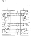
- FIG. 2 shows the transmission protocol of the parameter transmission. It can be seen that in the time in which the status bits, the addresses and the parameters are sent from the processing unit 4, the receiver 11 in the measuring system 1 is active and the transmitter 12 is inactive in the measuring system 1. It can also be seen that the transmitted data in commands B and C are acknowledged by returning this data to the processing unit 4. If it is determined in the processing unit 4 that the transmitted data is different from the received data, the transmission is repeated. From the measuring system 1, an 8-bit CRC is transmitted in addition to the data. CRC means cyclic redundance check, this data word is obtained by a known linkage of the data bits. This transmission of the CRC allows the processing unit 4 to check whether the data transmission has occurred without error. For reasons of clarity, the inverted status bits are not shown in FIG.
- FIG. 1 denotes the transmitter and 14 denotes the receiver of the processing unit 4. It can also be seen that the clock 15 is accommodated in the processing unit 4.
- the processing unit 4 or sequential electronics is preferably an NC controller.
- 5 two routes are shown in Figure 1 for the leiturig. According to the invention, the data in both directions but so on the same line 5 are transmitted bidirectionally, as shown in Figure 4 in detail.
- the analog values of the scanning device 10 are stored in the block 2.
- the measuring device 1 issues a start signal in the form of a start bit to the processing unit 4 in synchronism with a positive clock edge.
- the time tc is variable and depends on the amount of calculations.
- the start bit indicates that there is a valid position reading for transmission.
- the data bits of the measured value pending at the parallel-to-serial converter 3 are transmitted serially by the transmitter 12 via the data line 5 to the processing unit 4.
- the length of the measured value that is to say the necessary number of clocks, was communicated to the processing unit 4 before transmission as parameters from the memory 9.
- a CRC cyclic redundance check
- the formation of a CRC is known from data processing.
- FIG. 3 first the MSB is transmitted and finally the LSB of the measured value.
- FIGS. 4 to 6 first the LSB.
- FIGS. 4 and 5 also show the inverted status bits.
- the LSB is first transmitted, fast bit serial binary subtraction and addition at zero offset can be realized without much effort during transmission. Furthermore, this transmission has advantages in Codwertanschlußbeticianen according to DE 27 58 525 B1, DE 29 38 318 C3, DE 37 34 938 C2, since the coarser resolving code value is dependent on the finer-resolution code value ..
- the status information is again sent from the processing unit 4 to the measuring device 1 during the computing time tc.
- Positionsmeßaches In the transmission of Positionsmeß learners is distinguished between interrupted and continuous clock. For clarity, these two modes are shown in Figures 5 and 6 in detail.
- the interrupted clock according to Figure 5 is characterized in that the clock after the CRC transmission suspends until the storage of a new Positionsmeß learnerss.
- a status command Prior to each transmission of a position measurement value to the processing unit 4, a status command is sent by the processing unit 4.
- the interrupted clock is particularly intended for systems which are time-clocked, e.g. Control loops. If a measured value is to be transmitted again in the shortest possible time, it is also possible to select the operating mode according to FIG. 6 "continuous cycle". In this case, the waiting time tm and the time for transmitting the status information is saved. The last transmitted status information is used in the processing unit 4 as current status information.
- the processing unit 4 sends a status bit in each case synchronously with the falling clock edge.
- a takeover of the status bit from the measuring system 1 takes place synchronously to the rising clock edge.
- the memory area of the measuring system manufacturer is write-protected.
- the individual memory areas are distinguished by the code "Memory Range Select”.
- the memories can be occupied as follows:
- the value is subtracted from the zero point of the measuring system 1.
- These parameters may include fixed data by manufacturing, but also information about the operating state and operating parameters.
- For length measuring systems specifies the measuring step that is output by the measuring system during serial data transmission.
- For angle measuring systems the number of measuring steps per revolution is specified.
- Errors that have occurred are saved. If, for example, a bit is not equal to zero, the alarm bit is set when transmitting measured values according to FIG. An alarm message can also be used for emergency shutdown of a drive.
- warning messages are stored in the form of warning messages and can be read out on request.
- a warning message may be the word "battery replacement.” Warnings therefore allow for preventative maintenance.
- the processing unit 4 is adapted by taking over the necessary parameters from the measuring system 1 via the data line 5.
- the areas of the memory 9 may be divided by software, but it is also possible that the memory 9 consists of several individual memory units.
- the clock is predetermined by the processing unit 4. This ensures a synchronous data transmission.
- the invention can also be used when the clock is specified by the measuring system 1.
- a request signal (request) is sent to the measuring system 1 via the clock line 6 from the processing unit 4.
- the bits of the position measurement value are serially sent via the data line 5 to the processing unit 4.
- the internal clock of the measuring system 1 with a. Edge of the request signal are synchronized.
- the request signal can also be sent via the data line 5 to the measuring system 1.
- the invention can be used in angle and length measuring devices.
- the scanning principle is not limited to the photoelectric principle.
- the code for forming the position measurement value to be transmitted may be provided in a single track (chain code) or in several tracks on one or more code carriers.
Landscapes
- Engineering & Computer Science (AREA)
- Computer Hardware Design (AREA)
- Microelectronics & Electronic Packaging (AREA)
- Human Computer Interaction (AREA)
- Manufacturing & Machinery (AREA)
- Physics & Mathematics (AREA)
- General Physics & Mathematics (AREA)
- Automation & Control Theory (AREA)
- Arrangements For Transmission Of Measured Signals (AREA)
- Control Of Position Or Direction (AREA)
Claims (17)
- Dispositif pour la transmission de données en série entre un dispositif de mesure de position (1) et une unité de traitement (4), dans lequel- le dispositif de mesure de position (1) comprend un composant (2) dans lequel un mot codé binaire définissant la position absolue est formé à partir des signaux d'exploration d'au moins un dispositif d'exploration (10),- le mot codé binaire peut être amené à un composant d'émission (3) qui provoque une transmission en série par bit du mot codé par une ligne de données (5) en réponse à un ordre (Status) de l'unité de traitement (4),- le dispositif de mesure de position (1) comprend plusieurs zones de mémoire (8, 9),- une zone de mémoire (9) sert à la mémorisation de paramètres spécifiques du dispositif de mesure de position (1), lesquels peuvent également être transmis en série par ladite ligne de données (5) à l'unité de traitement (4), de sorte que l'unité de traitement (4) peut être adaptée à ces paramètres,- une zone de mémoire (8) supplémentaire sert au décodage d'ordres (Status) de l'unité de traitement (4), ces ordres (Status) pouvant également être amenés en tant que mots de données binaires en série par ladite ligne de données (5) au dispositif de mesure de position (1),- un générateur d'horloge (15) est prévu dans l'unité de traitement (4) et les trains d'impulsions d'horloge peuvent être amenés par une ligne d'horloge (6) à l'entrée d'horloge du composant d'émission (3),- les valeurs de mesure de position et les paramètres peuvent être transmis en synchronisme avec le train d'impulsions d'horloge en série par bit sur la ligne de données à l'unité de traitement (4),- la formation et la mémorisation de la valeur de mesure de position absolue momentanée dans le dispositif de mesure de position (1) sont déclenchées par un flanc d'impulsion d'horloge du train d'impulsions d'horloge,- après un temps de calcul (tc), qui dépend du volume des calculs, une signalisation de départ (Start) est transmise du dispositif de mesure de position (1) à l'unité de traitement (4), qui indique qu'une valeur de mesure de position valide est prête pour transmission.
- Dispositif suivant la revendication 1, caractérisé par le fait que dans la zone de mémoire (9) est mémorisé, en tant que paramètre spécifique, l'information concernant le nombre d'impulsions d'horloge, nécessaire pour la transmission de la valeur de mesure de position.
- Dispositif suivant l'une des revendications précédentes, caractérisé par le fait que des paramètres du dispositif de mesure de position (1) sont mémorisés dans une zone de mémoire (9) par le fabricant du dispositif de mesure de position (1) et que l'utilisateur du dispositif de mesure de position (1) n'a pas accès, à des fins d'inscription, à cette zone de mémoire (9).
- Dispositif suivant l'une des revendications précédentes, caractérisé par le fait que dans le dispositif de mesure de position (1) est prévue au moins une zone de mémoire (9) avec des paramètres spécifiques de l'utilisateur, zone à laquelle les paramètres peuvent être amenés par la ligne de données (5).
- Dispositif suivant l'une des revendications précédentes, caractérisé par le fait que dans le dispositif de mesure de position (1) est prévue au moins une zone de mémoire (9) avec des signalisations d'alarme et/ou d'erreur, zone qui peut être lue en passant par la ligne de données (5).
- Dispositif suivant l'une des revendications précédentes, caractérisé par le fait que le signal de la ligne de données (5) se trouve au niveau bas (LOW) à l'état de repos.
- Procédé pour la transmission de données en série entre un dispositif de mesure de position (1) et une unité de traitement (4), selon lequel- des ordres (Status) sont transmis en série par bit en tant que mots de données de l'unité de traitement (4) au dispositif de mesure de position (1) et le dispositif de mesure de position (1) est amené, en réponse à cette transmission, à exécuter un ordre (Status) et, en fonction de l'ordre (Status), à émettre une valeur de mesure de position en tant que mot de données binaire ou un paramètre mémorisé dans le dispositif de mesure de position (1) en tant que mot de données binaire à l'unité de traitement (4), de sorte que l'unité de traitement (4) peut être adaptée à ce paramètre, ou amène le dispositif de mesure de position (1) à recevoir des paramètres de l'unité de traitement (4) et à les mémoriser dans une zone de mémoire (9),- les ordres (Status), les paramètres et les valeurs de mesure de position sont transmis en synchronisme avec l'horloge sur une ligne de données commune (5)- le train d'impulsions d'horloge pour la transmission en synchronisme est transmis de l'unité de traitement (4) par une ligne d'horloge (6) au dispositif de mesure de position (1)- la formation et la mémorisation de la valeur de mesure de position absolue momentanée dans le dispositif de mesure de position (1) sont déclenchées par un flanc d'impulsion d'horloge du train d'impulsions d'horloge,- après un temps de calcul (tc), qui dépend du volume des calculs, une signalisation de départ (Start) est transmise du dispositif de mesure de position (1) à l'unité de traitement (4), qui indique qu'une valeur de mesure de position valide est prête pour transmission.
- Procédé selon la revendication 7, caractérisé par le fait que l'unité de traitement (4) émet chaque fois un bit de l'ordre (Status) en synchronisme avec un flanc descendant.
- Procédé selon une des revendications 7 ou 8, caractérisé par le fait qu'à un flanc négatif du train d'impulsions d'horloge les valeurs analogiques du dispositif d'exploration (10) sont mémorisées dans le composant (2) et la formation et la mémorisation de la valeur de mesure de position absolue instantanée dans le dispositif de mesure de position sont.
- Procédé selon une des revendications 7 à 9, caractérisé par le fait que la signalisation de départ (Start) est transmise après le temps de calcul (tc), en synchronisme avec un flanc d'impulsion d'horloge positif.
- Procédé selon une des revendications 7 ou 10, caractérisé par le fait- qu'après la signalisation de départ (Start), une signalisation d'alarme (Alarrn) sous la forme d'un bit d'alarme est transmise à l'unité de traitement (4), et un dysfonctionnement du dispositif de mesure (1) est signalé à l'unité de traitement (4),- le mot de données de la valeur de mesure de position est ensuite transmis à l'unité de traitement (4).
- Procédé selon une des revendications 7 à 11, caractérisé par le fait que lors de la transmission en série par bit de la valeur de mesure de position, le bit de poids le plus faible est transmis en premier.
- Procédé selon une des revendications 7 à 12, caractérisé par le fait qu'il est prévu dans le dispositif de mesure (1), une zone de mémoire (9) dans laquelle est mémorisée, en cas d'erreur ou en cas de dépassement de tolérances prédéterminées, une information d'erreur qui est lue sur appel de l'unité de traitement (4).
- Procédé selon une des revendications 7 à 13, caractérisé par le fait qu'après la transmission de la valeur de mesure de position, un mot de données (CRC), pour le contrôle de la valeur de mesure de position transmise, est transmis à l'unité de traitement (4).
- Procédé selon la revendication 14, caractérisé par le fait que l'impulsion d'horloge après la transmission du mot de données (CRC) est supprimée jusqu'à la mémorisation d'une nouvelle valeur de mesure de position et, avant chaque transmission d'une valeur de mesure de position, un ordre (Status) est envoyé par l'unité de traitement (4).
- Procédé selon une des revendications 7 à 15, caractérisé par le fait qu'un mode de fonctionnement peut être sélectionné dans lequel les impulsions d'horloge se déroulent sans interruption et sur la base d'un ordre (Status) plusieurs valeurs de mesure de position sont transmises les unes à la suite des autres à l'unité de traitement (4) sans transmission intermédiaire d'un ordre (Status) d'appel de l'unité de traitement (4).
- Procédé selon une des revendications 7 à 16, caractérisé par le fait que- les informations nécessaires à la transmission d'une valeur de mesure de position sur le nombre d'impulsions d'horloge sont mémorisées dans le dispositif de mesure de position (1),- cette information est lue par l'unité de traitement (4) et- le nombre nécessaire d'impulsions d'horloge pour la transmission de la valeur de mesure du dispositif de mesure (1) est mis à disposition par l'unité de traitement (4).
Applications Claiming Priority (2)
| Application Number | Priority Date | Filing Date | Title |
|---|---|---|---|
| DE4342377 | 1993-12-13 | ||
| DE4342377A DE4342377B4 (de) | 1993-12-13 | 1993-12-13 | Anordnung und Verfahren zur seriellen Datenübertragung einer Positionsmeßeinrichtung |
Publications (3)
| Publication Number | Publication Date |
|---|---|
| EP0660209A1 EP0660209A1 (fr) | 1995-06-28 |
| EP0660209B1 EP0660209B1 (fr) | 1996-10-30 |
| EP0660209B2 true EP0660209B2 (fr) | 2006-06-14 |
Family
ID=6504818
Family Applications (1)
| Application Number | Title | Priority Date | Filing Date |
|---|---|---|---|
| EP94119466A Expired - Lifetime EP0660209B2 (fr) | 1993-12-13 | 1994-12-09 | Méthode et dispositif pour la transmission en série de données entre un appareil de mesure de position et une unité de traitement de données |
Country Status (3)
| Country | Link |
|---|---|
| EP (1) | EP0660209B2 (fr) |
| AT (1) | ATE144845T1 (fr) |
| DE (2) | DE4342377B4 (fr) |
Cited By (8)
| Publication number | Priority date | Publication date | Assignee | Title |
|---|---|---|---|---|
| DE102007041744A1 (de) | 2007-09-04 | 2009-03-12 | Tr Electronic Gmbh | Verfahren und Vorrichtung zum Übertragen von Daten |
| WO2009149966A1 (fr) * | 2008-06-11 | 2009-12-17 | Dr. Johannes Heidenhain Gmbh | Dispositif et procédé de transmission de données en série entre un appareil de mesure de position et une unité de commande |
| DE102008053105A1 (de) | 2008-10-24 | 2010-04-29 | Dr. Johannes Heidenhain Gmbh | Vorrichtung und Verfahren zur Datenübertragung zwischen einem Positionsmessgerät und einer Folgeelektronik |
| DE102008054887A1 (de) | 2008-12-18 | 2010-07-01 | Dr. Johannes Heidenhain Gmbh | Vorrichtung und Verfahren zur automatisierten Erkennung einer Schnittstelle |
| DE102010038552A1 (de) | 2010-07-28 | 2012-02-02 | Dr. Johannes Heidenhain Gmbh | Vorrichtung zur Manipulation von Schnittstellensignalen |
| DE102011006300A1 (de) | 2011-03-29 | 2012-10-04 | Dr. Johannes Heidenhain Gmbh | Verfahren und Überwachungseinheit zur Überprüfung von Positionswerten |
| DE102012201170A1 (de) | 2012-01-27 | 2013-08-01 | Dr. Johannes Heidenhain Gmbh | Vorrichtung zur Übertragung von Sensordaten |
| DE102012205802A1 (de) | 2012-04-10 | 2013-10-10 | Dr. Johannes Heidenhain Gmbh | Vorrichtung und Verfahren zur Übertragung von Energie und Daten zwischen einer Steuerungseinheit und einem Positionsmessgerät |
Families Citing this family (36)
| Publication number | Priority date | Publication date | Assignee | Title |
|---|---|---|---|---|
| EP0790489B1 (fr) | 1996-02-16 | 2000-05-17 | Dr. Johannes Heidenhain GmbH | Dispositif et procédé pour commuter entre plusieurs modes opératoires d'un dispositif de mesure |
| DE19727352A1 (de) * | 1996-07-10 | 1998-01-15 | Heidenhain Gmbh Dr Johannes | Verfahren zur Positionsbestimmung und hierzu geeignetes Meßsystem |
| DE19711218C1 (de) * | 1997-03-18 | 1998-04-09 | Heidenhain Gmbh Dr Johannes | Verfahren und Vorrichtung zur Übertragung von Daten zwischen einer Positionsmeßeinrichtung und einer Auswerteeinheit |
| DE19711216C1 (de) * | 1997-03-18 | 1998-05-07 | Heidenhain Gmbh Dr Johannes | Verfahren und Vorrichtung zur Übertragung von Daten zwischen einer Positionsmeßeinrichtung und einer Auswerteeinheit |
| JP2000028393A (ja) * | 1998-07-08 | 2000-01-28 | Canon Inc | 測定ユニット、管理ユニット、駆動ユニット、駆動システム、及び測定装置 |
| DE19933963A1 (de) * | 1999-07-20 | 2001-02-01 | Heidenhain Gmbh Dr Johannes | Verfahren und Anordnung zur Datenübertragung zwischen verschiedenen Speichereinheiten von Positionsmeßeinrichtungen |
| DE50112891D1 (de) | 2000-02-17 | 2007-10-04 | Heidenhain Gmbh Dr Johannes | Positionsmesseinrichtung und Verfahren zu deren Betrieb |
| JP4889855B2 (ja) * | 2000-02-17 | 2012-03-07 | ドクトル・ヨハネス・ハイデンハイン・ゲゼルシヤフト・ミツト・ベシユレンクテル・ハフツング | 位置測定装置 |
| DE10030357A1 (de) | 2000-06-21 | 2002-01-17 | Heidenhain Gmbh Dr Johannes | Verfahren und Vorrichtung zur seriellen Datenübertragung zwischen einem Positionsmesssystem und einer Verarbeitungseinheit |
| DE10030358A1 (de) * | 2000-06-21 | 2002-01-03 | Heidenhain Gmbh Dr Johannes | Verfahren und Vorrichtung zur seriellen Datenübertragung zwischen einem Positionsmesssystem und einer Verarbeitungseinheit |
| DE10050392A1 (de) * | 2000-10-12 | 2002-04-18 | Heidenhain Gmbh Dr Johannes | Positionsmesseinrichtung und Verfahren zum Betrieb einer Positionsmesseinrichtung |
| DE10055996A1 (de) * | 2000-11-11 | 2002-05-23 | Heidenhain Gmbh Dr Johannes | Positionsmessgerät und Verfahren zur Inbetriebnahme eines Positionsmessgerätes |
| US7031031B1 (en) | 2000-12-06 | 2006-04-18 | Dr. Johannes Heidenhain Gmbh | Position measuring system |
| DE10117194B4 (de) | 2001-04-05 | 2013-09-19 | Anton Rodi | Winkel- oder Wegmessgeber |
| GB0111482D0 (en) * | 2001-05-10 | 2001-07-04 | Fast Technology Ag | Data transfer protocol |
| DE10123292B4 (de) * | 2001-05-13 | 2010-07-22 | Anton Rodi | Sensorsystem |
| DE10125533B4 (de) * | 2001-05-23 | 2005-06-02 | Dr. Johannes Heidenhain Gmbh | Verfahren zum Betrieb einer Positionsmesseinrichtung sowie Positionsmesseinrichtung und Auswerteeinheit zur Durchführung des Verfahrens |
| DE10137835A1 (de) * | 2001-08-02 | 2003-02-20 | Siedle Horst Gmbh & Co Kg | Schnittstelle zum seriellen Übertragen von digitalen Daten |
| ATE378576T1 (de) | 2002-09-25 | 2007-11-15 | Heidenhain Gmbh Dr Johannes | Verfahren zum betrieb einer positionsmesseinrichtung und geeignete positionsmesseinrichtung hierzu |
| EP1947422B1 (fr) * | 2007-01-19 | 2011-11-23 | SICK STEGMANN GmbH | Procédé et appareil pour paramétrer un dispositif de mesure |
| EP2138916B1 (fr) * | 2008-06-24 | 2014-05-07 | SICK STEGMANN GmbH | Système de mesure de position |
| CN102575945B (zh) * | 2009-09-09 | 2015-07-01 | 株式会社安川电机 | 变频器装置及变频器系统 |
| ES2461969T3 (es) * | 2011-03-22 | 2014-05-21 | Agie Charmilles Sa | Procedimiento y dispositivo para la transmisión digital de datos |
| DE102012201651A1 (de) | 2012-02-03 | 2013-08-08 | Dr. Johannes Heidenhain Gmbh | Positionsmesseinrichtung |
| DE102012218890A1 (de) | 2012-10-17 | 2014-04-17 | Dr. Johannes Heidenhain Gmbh | Absolutes Positionsmessgerät |
| DE102013208629A1 (de) | 2013-05-10 | 2014-11-13 | Dr. Johannes Heidenhain Gmbh | Positionsmesseinrichtung |
| DE102013209019A1 (de) | 2013-05-15 | 2014-11-20 | Dr. Johannes Heidenhain Gmbh | Verfahren zur Übertragung von Daten zwischen einer Positionsmesseinrichtung und einer zugeordneten Verarbeitungseinheit sowie Positionsmesseinrichtung hierfür |
| DE102013219099A1 (de) | 2013-09-24 | 2015-03-26 | Dr. Johannes Heidenhain Gmbh | Absolutes Positionsmessgerät |
| DE102013219277A1 (de) | 2013-09-25 | 2015-03-26 | Dr. Johannes Heidenhain Gmbh | Positionsmesseinrichtung und Verfahren zur Überprüfung eines Arbeitstaktsignals |
| DE102014204155A1 (de) | 2014-03-06 | 2015-09-10 | Dr. Johannes Heidenhain Gmbh | Vorrichtung zur Signalübertragung |
| DE102014212288A1 (de) * | 2014-06-26 | 2015-12-31 | Dr. Johannes Heidenhain Gmbh | Vorrichtung und Verfahren zum Erzeugen eines Triggersignals in einer Positionsmesseinrichtung und Positionsmesseinrichtung hierzu |
| DE102014225867A1 (de) | 2014-12-15 | 2016-06-16 | Dr. Johannes Heidenhain Gmbh | Vorrichtung und Verfahren zur Überprüfung eines Arbeitstaktsignals einer Positionsmesseinrichtung |
| FR3035495B1 (fr) * | 2015-04-23 | 2017-05-26 | Meggitt (Sensorex) | Systeme de mesure des deplacements d'un organe mobile notamment d'un aeronef |
| DE102015208409A1 (de) | 2015-05-06 | 2016-11-10 | Dr. Johannes Heidenhain Gmbh | Vorrichtung und Verfahren zur Verarbeitung von seriellen Datenrahmen |
| DE102016212115A1 (de) | 2016-07-04 | 2018-01-04 | Dr. Johannes Heidenhain Gmbh | Vorrichtung und Verfahren zur Datenübertragung |
| DE102019213982A1 (de) | 2019-09-13 | 2021-03-18 | Dr. Johannes Heidenhain Gmbh | Vorrichtung und Verfahren zur synchron-seriellen Datenübertragung |
Family Cites Families (7)
| Publication number | Priority date | Publication date | Assignee | Title |
|---|---|---|---|---|
| DE2758525B1 (de) * | 1977-12-28 | 1979-06-28 | Heidenhain Gmbh Dr Johannes | Messeinrichtung mit codierter Unterteilung |
| DE3340946A1 (de) * | 1983-11-11 | 1985-05-23 | Siemens AG, 1000 Berlin und 8000 München | Handhabungseinrichtung, insbesondere industrieroboter, mit mindestens einem sensor |
| EP0171579B1 (fr) * | 1984-07-13 | 1988-03-09 | Max Stegmann Gmbh Uhren- und Elektroapparatefabrik | Dispositif pour transmettre en séries les valeurs mesurées d'au moins un transducteur |
| US4912476A (en) * | 1985-05-03 | 1990-03-27 | Unisys Corporation | Antenna interface common module |
| DE3910718A1 (de) * | 1989-04-03 | 1990-10-04 | Siemens Ag | Ueberwachungsgeraet mit schaltvorrichtung |
| DE3936452A1 (de) * | 1989-11-02 | 1991-05-08 | Heidenhain Gmbh Dr Johannes | Verfahren zum anpassen einer numerischen steuerung an maschinen- und/oder messsystem-parameter |
| DE4129577C2 (de) * | 1991-09-06 | 1999-11-25 | Mueller Arnold Gmbh Co Kg | Meßsystem zur Drehwinkelmessung |
-
1993
- 1993-12-13 DE DE4342377A patent/DE4342377B4/de not_active Expired - Lifetime
-
1994
- 1994-12-09 AT AT94119466T patent/ATE144845T1/de not_active IP Right Cessation
- 1994-12-09 DE DE59400945T patent/DE59400945D1/de not_active Expired - Lifetime
- 1994-12-09 EP EP94119466A patent/EP0660209B2/fr not_active Expired - Lifetime
Cited By (11)
| Publication number | Priority date | Publication date | Assignee | Title |
|---|---|---|---|---|
| DE102007041744A1 (de) | 2007-09-04 | 2009-03-12 | Tr Electronic Gmbh | Verfahren und Vorrichtung zum Übertragen von Daten |
| WO2009149966A1 (fr) * | 2008-06-11 | 2009-12-17 | Dr. Johannes Heidenhain Gmbh | Dispositif et procédé de transmission de données en série entre un appareil de mesure de position et une unité de commande |
| DE102008027902A1 (de) | 2008-06-11 | 2009-12-17 | Dr. Johannes Heidenhain Gmbh | Vorrichtung und Verfahren zur seriellen Datenübertragung zwischen einem Positionsmessgerät und einer Steuerungseinheit |
| DE102008053105A1 (de) | 2008-10-24 | 2010-04-29 | Dr. Johannes Heidenhain Gmbh | Vorrichtung und Verfahren zur Datenübertragung zwischen einem Positionsmessgerät und einer Folgeelektronik |
| DE102008054887A1 (de) | 2008-12-18 | 2010-07-01 | Dr. Johannes Heidenhain Gmbh | Vorrichtung und Verfahren zur automatisierten Erkennung einer Schnittstelle |
| US10120359B2 (en) | 2008-12-18 | 2018-11-06 | Dr. Johannes Heidenhain Gmbh | Device and method for the automated detection of an interface |
| DE102008054887B4 (de) * | 2008-12-18 | 2021-03-25 | Dr. Johannes Heidenhain Gmbh | Vorrichtung und Verfahren zur automatisierten Erkennung einer Schnittstelle |
| DE102010038552A1 (de) | 2010-07-28 | 2012-02-02 | Dr. Johannes Heidenhain Gmbh | Vorrichtung zur Manipulation von Schnittstellensignalen |
| DE102011006300A1 (de) | 2011-03-29 | 2012-10-04 | Dr. Johannes Heidenhain Gmbh | Verfahren und Überwachungseinheit zur Überprüfung von Positionswerten |
| DE102012201170A1 (de) | 2012-01-27 | 2013-08-01 | Dr. Johannes Heidenhain Gmbh | Vorrichtung zur Übertragung von Sensordaten |
| DE102012205802A1 (de) | 2012-04-10 | 2013-10-10 | Dr. Johannes Heidenhain Gmbh | Vorrichtung und Verfahren zur Übertragung von Energie und Daten zwischen einer Steuerungseinheit und einem Positionsmessgerät |
Also Published As
| Publication number | Publication date |
|---|---|
| DE59400945D1 (de) | 1996-12-05 |
| DE4342377B4 (de) | 2010-08-12 |
| EP0660209B1 (fr) | 1996-10-30 |
| DE4342377A1 (de) | 1995-06-14 |
| EP0660209A1 (fr) | 1995-06-28 |
| ATE144845T1 (de) | 1996-11-15 |
Similar Documents
| Publication | Publication Date | Title |
|---|---|---|
| EP0660209B2 (fr) | Méthode et dispositif pour la transmission en série de données entre un appareil de mesure de position et une unité de traitement de données | |
| EP0120196B1 (fr) | Agencement de circuit pour la signalisation optique de variables | |
| DE69534349T2 (de) | Steuereinrichtung mit Fehlersicherheitsfunktion, automatische Steuereinrichtung für Züge und diese verwendendes System | |
| EP2040957B1 (fr) | Procédé et dispositif de contrôle de plausibilité de valeurs de mesure dans l'environnement d'un véhicule à moteur | |
| EP1923670B1 (fr) | Dispositif de mesure de position | |
| EP1327119B2 (fr) | Dispositif de mesure de position et procede pour faire fonctionner ce dispositif | |
| EP1666847A2 (fr) | Capteur de mesure pourvu d'un traitement de signal absolu et d'une sortie de signal incrémentielle | |
| EP2223049A1 (fr) | Procédé d'acquisition sécurisée de plusieurs signaux d'entrée analogiques, circuit d'entrée analogique ainsi que capteur de mesure et convertisseur de mesure équipés dudit circuit d'entrée analogique | |
| DE102014101945A1 (de) | Messumformer mit Überwachungsfunktion | |
| DE3687765T2 (de) | Digitales automatisches flugsteuersystem. | |
| DE10392545B4 (de) | Elektronische Schaltungsanordnung zur fehlerabgesicherten Analog-/Digital-Umwandlung von Signalen | |
| DE3309920A1 (de) | Kraftfahrzeug | |
| EP0451505B1 (fr) | Système de mesure de la position incrémentiel | |
| DE19508834C2 (de) | Positonsmeßsystem | |
| WO2007101658A1 (fr) | Procédé d'enregistrement des modifications de signaux d'entrée | |
| DE10063449B4 (de) | Steuergerät mit einer Konsistenzüberwachung von Interrupts und ein Verfahren zur Durchführung einer Konsistenzüberwachung von Interrupts bei einem Steuergerät | |
| EP3296184B1 (fr) | Dispositif et procede destine a surveiller l'arret de vehicules, en particulier des vehicules sur rails | |
| DE102010040801A1 (de) | Trennwand mit mehreren verfahrbaren Wandelementen und ein Verfahren zur Steuerung dieser Trennwand | |
| DE102017218054A1 (de) | Verfahren zur Auswertung von Daten mindestens eines Raddrehzahlsensors und Steuergerät | |
| DE102008034318B4 (de) | Anordnung zur Auswertung der Messwerte eines Messwertwandlers | |
| DE10152216B4 (de) | Verfahren und Anordnung zum Überwachen eines Bus-Systems | |
| EP3091685B1 (fr) | Dispositif et procede destines a la preparation de trames de donnees en serie | |
| DE19521252C2 (de) | Anordnung zum Übertragen von Positionsmeßsignalen | |
| EP0425897B1 (fr) | Procédé de fonctionnement d'un dispositif de commande | |
| EP0601214B1 (fr) | Méthode pour observer des signaux |
Legal Events
| Date | Code | Title | Description |
|---|---|---|---|
| PUAI | Public reference made under article 153(3) epc to a published international application that has entered the european phase |
Free format text: ORIGINAL CODE: 0009012 |
|
| AK | Designated contracting states |
Kind code of ref document: A1 Designated state(s): AT CH DE FR GB IT LI |
|
| 17P | Request for examination filed |
Effective date: 19951228 |
|
| GRAG | Despatch of communication of intention to grant |
Free format text: ORIGINAL CODE: EPIDOS AGRA |
|
| GRAH | Despatch of communication of intention to grant a patent |
Free format text: ORIGINAL CODE: EPIDOS IGRA |
|
| 17Q | First examination report despatched |
Effective date: 19960403 |
|
| GRAH | Despatch of communication of intention to grant a patent |
Free format text: ORIGINAL CODE: EPIDOS IGRA |
|
| ITF | It: translation for a ep patent filed | ||
| GRAA | (expected) grant |
Free format text: ORIGINAL CODE: 0009210 |
|
| AK | Designated contracting states |
Kind code of ref document: B1 Designated state(s): AT CH DE FR GB IT LI |
|
| REF | Corresponds to: |
Ref document number: 144845 Country of ref document: AT Date of ref document: 19961115 Kind code of ref document: T |
|
| REG | Reference to a national code |
Ref country code: CH Ref legal event code: NV Representative=s name: TROESCH SCHEIDEGGER WERNER AG |
|
| ET | Fr: translation filed | ||
| GBT | Gb: translation of ep patent filed (gb section 77(6)(a)/1977) |
Effective date: 19961030 |
|
| REF | Corresponds to: |
Ref document number: 59400945 Country of ref document: DE Date of ref document: 19961205 |
|
| PLBQ | Unpublished change to opponent data |
Free format text: ORIGINAL CODE: EPIDOS OPPO |
|
| PLBI | Opposition filed |
Free format text: ORIGINAL CODE: 0009260 |
|
| PLBF | Reply of patent proprietor to notice(s) of opposition |
Free format text: ORIGINAL CODE: EPIDOS OBSO |
|
| 26 | Opposition filed |
Opponent name: MAX STEGMANN GMBH ANTRIEBSTECHNIK - ELEKTRONIK Effective date: 19970729 |
|
| PLBF | Reply of patent proprietor to notice(s) of opposition |
Free format text: ORIGINAL CODE: EPIDOS OBSO |
|
| PLBF | Reply of patent proprietor to notice(s) of opposition |
Free format text: ORIGINAL CODE: EPIDOS OBSO |
|
| REG | Reference to a national code |
Ref country code: GB Ref legal event code: IF02 |
|
| PLAW | Interlocutory decision in opposition |
Free format text: ORIGINAL CODE: EPIDOS IDOP |
|
| APAC | Appeal dossier modified |
Free format text: ORIGINAL CODE: EPIDOS NOAPO |
|
| APAC | Appeal dossier modified |
Free format text: ORIGINAL CODE: EPIDOS NOAPO |
|
| APAA | Appeal reference recorded |
Free format text: ORIGINAL CODE: EPIDOS REFN |
|
| PLAB | Opposition data, opponent's data or that of the opponent's representative modified |
Free format text: ORIGINAL CODE: 0009299OPPO |
|
| APAH | Appeal reference modified |
Free format text: ORIGINAL CODE: EPIDOSCREFNO |
|
| APBU | Appeal procedure closed |
Free format text: ORIGINAL CODE: EPIDOSNNOA9O |
|
| PUAH | Patent maintained in amended form |
Free format text: ORIGINAL CODE: 0009272 |
|
| STAA | Information on the status of an ep patent application or granted ep patent |
Free format text: STATUS: PATENT MAINTAINED AS AMENDED |
|
| 27A | Patent maintained in amended form |
Effective date: 20060614 |
|
| AK | Designated contracting states |
Kind code of ref document: B2 Designated state(s): AT CH DE FR GB IT LI |
|
| REG | Reference to a national code |
Ref country code: CH Ref legal event code: AEN Free format text: AUFRECHTERHALTUNG DES PATENTES IN GEAENDERTER FORM |
|
| GBTA | Gb: translation of amended ep patent filed (gb section 77(6)(b)/1977) |
Effective date: 20060719 |
|
| ET3 | Fr: translation filed ** decision concerning opposition | ||
| PGFP | Annual fee paid to national office [announced via postgrant information from national office to epo] |
Ref country code: AT Payment date: 20081215 Year of fee payment: 15 |
|
| PG25 | Lapsed in a contracting state [announced via postgrant information from national office to epo] |
Ref country code: AT Free format text: LAPSE BECAUSE OF NON-PAYMENT OF DUE FEES Effective date: 20091209 |
|
| PGFP | Annual fee paid to national office [announced via postgrant information from national office to epo] |
Ref country code: DE Payment date: 20131220 Year of fee payment: 20 Ref country code: CH Payment date: 20131219 Year of fee payment: 20 Ref country code: GB Payment date: 20131219 Year of fee payment: 20 |
|
| PGFP | Annual fee paid to national office [announced via postgrant information from national office to epo] |
Ref country code: IT Payment date: 20131217 Year of fee payment: 20 |
|
| PGFP | Annual fee paid to national office [announced via postgrant information from national office to epo] |
Ref country code: FR Payment date: 20131220 Year of fee payment: 20 |
|
| REG | Reference to a national code |
Ref country code: DE Ref legal event code: R071 Ref document number: 59400945 Country of ref document: DE |
|
| REG | Reference to a national code |
Ref country code: CH Ref legal event code: PL |
|
| REG | Reference to a national code |
Ref country code: GB Ref legal event code: PE20 Expiry date: 20141208 |
|
| PG25 | Lapsed in a contracting state [announced via postgrant information from national office to epo] |
Ref country code: GB Free format text: LAPSE BECAUSE OF EXPIRATION OF PROTECTION Effective date: 20141208 |