EP0660209B2 - Method and device for serial transmission of data between a position sensing means and a data processing unit - Google Patents
Method and device for serial transmission of data between a position sensing means and a data processing unit Download PDFInfo
- Publication number
- EP0660209B2 EP0660209B2 EP94119466A EP94119466A EP0660209B2 EP 0660209 B2 EP0660209 B2 EP 0660209B2 EP 94119466 A EP94119466 A EP 94119466A EP 94119466 A EP94119466 A EP 94119466A EP 0660209 B2 EP0660209 B2 EP 0660209B2
- Authority
- EP
- European Patent Office
- Prior art keywords
- processing unit
- measuring device
- clock
- transmitted
- position measuring
- Prior art date
- Legal status (The legal status is an assumption and is not a legal conclusion. Google has not performed a legal analysis and makes no representation as to the accuracy of the status listed.)
- Expired - Lifetime
Links
Images


Classifications
-
- G—PHYSICS
- G05—CONTROLLING; REGULATING
- G05B—CONTROL OR REGULATING SYSTEMS IN GENERAL; FUNCTIONAL ELEMENTS OF SUCH SYSTEMS; MONITORING OR TESTING ARRANGEMENTS FOR SUCH SYSTEMS OR ELEMENTS
- G05B19/00—Program-control systems
- G05B19/02—Program-control systems electric
- G05B19/18—Numerical control [NC], i.e. automatically operating machines, in particular machine tools, e.g. in a manufacturing environment, so as to execute positioning, movement or co-ordinated operations by means of program data in numerical form
- G05B19/414—Structure of the control system, e.g. common controller or multiprocessor systems, interface to servo, programmable interface controller
- G05B19/4142—Structure of the control system, e.g. common controller or multiprocessor systems, interface to servo, programmable interface controller characterised by the use of a microprocessor
-
- G—PHYSICS
- G05—CONTROLLING; REGULATING
- G05B—CONTROL OR REGULATING SYSTEMS IN GENERAL; FUNCTIONAL ELEMENTS OF SUCH SYSTEMS; MONITORING OR TESTING ARRANGEMENTS FOR SUCH SYSTEMS OR ELEMENTS
- G05B2219/00—Program-control systems
- G05B2219/30—Nc systems
- G05B2219/33—Director till display
- G05B2219/33234—Detect bad data transfer
-
- G—PHYSICS
- G05—CONTROLLING; REGULATING
- G05B—CONTROL OR REGULATING SYSTEMS IN GENERAL; FUNCTIONAL ELEMENTS OF SUCH SYSTEMS; MONITORING OR TESTING ARRANGEMENTS FOR SUCH SYSTEMS OR ELEMENTS
- G05B2219/00—Program-control systems
- G05B2219/30—Nc systems
- G05B2219/33—Director till display
- G05B2219/33254—Serial position feedback, serial to parallel conversion and reverse
-
- G—PHYSICS
- G05—CONTROLLING; REGULATING
- G05B—CONTROL OR REGULATING SYSTEMS IN GENERAL; FUNCTIONAL ELEMENTS OF SUCH SYSTEMS; MONITORING OR TESTING ARRANGEMENTS FOR SUCH SYSTEMS OR ELEMENTS
- G05B2219/00—Program-control systems
- G05B2219/30—Nc systems
- G05B2219/34—Director, elements to supervisory
- G05B2219/34012—Smart, intelligent I-O coprocessor, programmable sensor interface
-
- G—PHYSICS
- G05—CONTROLLING; REGULATING
- G05B—CONTROL OR REGULATING SYSTEMS IN GENERAL; FUNCTIONAL ELEMENTS OF SUCH SYSTEMS; MONITORING OR TESTING ARRANGEMENTS FOR SUCH SYSTEMS OR ELEMENTS
- G05B2219/00—Program-control systems
- G05B2219/30—Nc systems
- G05B2219/37—Measurements
- G05B2219/37154—Encoder and absolute position counter
-
- G—PHYSICS
- G05—CONTROLLING; REGULATING
- G05B—CONTROL OR REGULATING SYSTEMS IN GENERAL; FUNCTIONAL ELEMENTS OF SUCH SYSTEMS; MONITORING OR TESTING ARRANGEMENTS FOR SUCH SYSTEMS OR ELEMENTS
- G05B2219/00—Program-control systems
- G05B2219/30—Nc systems
- G05B2219/37—Measurements
- G05B2219/37494—Intelligent sensor, data handling incorporated in sensor
-
- H—ELECTRICITY
- H04—ELECTRIC COMMUNICATION TECHNIQUE
- H04L—TRANSMISSION OF DIGITAL INFORMATION, e.g. TELEGRAPHIC COMMUNICATION
- H04L7/00—Arrangements for synchronising receiver with transmitter
- H04L7/0008—Synchronisation information channels, e.g. clock distribution lines
Definitions
- the invention relates to a device and a method for serial data transmission between a position measuring device and a processing unit, in particular an NC controller.
- the processing unit must be adapted by the user to the specific parameters of the position measuring device. For example, the number of clocks required to complete the transmission of a position measurement value depends on the resolution of the position measurement device. So far, the processing unit has specified a fixed number of pulses (for example, 13). If a position measuring device with low resolution (for example 5 bits) is used, then the 13 clocks are still used for the measured value transmission. It can be seen that this unnecessary idle time is consumed.
- the invention is therefore based on the object to optimize the adaptation of the processing unit to specific parameters of the position measuring and minimize the cost of transmission lines between the position and the processing unit.
- the particular advantages of the invention are that the specific parameters of the position measuring device can be taken over automatically by the processing unit, wherein the same lines are used to transmit these parameters, which are already present for the measured value transmission. Furthermore, a secure transmission is guaranteed.
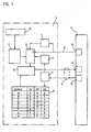
- the reference numeral 1 designates an angle measuring device which transmits the respective absolute position as binary data word to a processing unit 4.
- a processing unit 4 By known photoelectrical reduction of one code disk or several code disks (multiturn) connected via reduction gears generated by a scanning device 10 analog scanning signals, which are supplied to a block 2.
- the scanning signals are amplified and converted into digital signals to a binary data word.
- Block 2 ensures that the complete absolute position value is always present at the output regardless of the code of the code disks present.
- the code of the code slices can be formed as a gray code or from a plurality of incremental tracks with a different graduation period (DE 41 25 B65 A1).
- the block 2 can also be used to correct the analog or digital signals, as well as necessary calculations are performed in the block 2, the correct connection or for the correct combination of several Codespuren.als. Groups of code tracks are required. These calculations are described in detail, for example, in DE 27 58 525 B1, DE 29 38 31 8 C3 or DE 37 34 938 C2.
- the absolute Positionmeßwert is a parallel-to-serial converter Supplied as output module, which sends controlled by a clock pulse sequence, the individual bits of the absolute position measurement determining data word serially via the data line 5 to the processing unit 4. It is particularly advantageous if the clock pulse sequence is specified by the processing unit 4.
- a clock line 6 is provided to transmit the clock pulses from the processing unit 4 to the angle measuring device 1.
- the transmission of the position measurement value takes place by means of a retriggerable time step 7, as described in detail in EP 0 171 579 B1, to which reference is expressly made.
- commands are also transmitted from the processing unit 4 to the position measuring device 1 via the data line 5.
- the commands are supplied to a memory 8 of the position measuring device 1 which decodes the command and causes the position measuring device 1 to execute the corresponding command.
- this command is a data word consisting of three status bits S2 S1 and SO.
- each status bit is also transmitted inverted, so that a total of six status bits S2, S1, S0, S 2 ⁇ . S 1 ⁇ . S 0 ⁇ for a command from the processing unit 4 to the position measuring device 1 are transmitted. If the position measuring device 1 detects an erroneous status bit transmission, an error message occurs.
- the position measuring device 1 is hereinafter referred to only as a measuring system.
- the example shows eight status commands A to H, which are described in detail below:
- the measuring device 1 includes a memory 9 in which parameters of the measuring device 1 can be stored. Additional memories or memory areas may be provided for correction values. It is also possible to provide in the memory 9 a region in which the user has specific user parameters, e.g. Motor data stores. It is particularly advantageous if the memory 9 is divided in such a way that the area with the parameters of the measuring system 1 can only be described by the measuring system manufacturer, and another area is freely accessible to the user (writable and readable). The range with the parameters of the measuring system manufacturer can in turn be divided into an area which can be read by the user and an area which is readable exclusively by the measuring system manufacturer.
- the memory selection is first activated with the command B to read or write parameters.
- command B a 16-bit data word (Memory Range Select Code) is sent from the processing unit 4 to the measurement system 1 to select a region of the memory 9.
- the command is acknowledged by the measuring system.
- the measuring device 1 is informed with this command C that parameters are subsequently fed to the measuring system 1 under a specific address. That is, after this status command C, first the address information under which the parameters are to be stored and subsequently the parameter information is supplied from the processing unit 4 to the measuring device 1 via the data line 5.
- the measuring device 1 is informed with this command D that the processing unit 4 expects the transmission of stored parameters of the measuring device 1.
- the processing unit 1 additionally indicates the address where these parameters are stored in the measuring device 1.
- FIG. 2 shows the transmission protocol of the parameter transmission. It can be seen that in the time in which the status bits, the addresses and the parameters are sent from the processing unit 4, the receiver 11 in the measuring system 1 is active and the transmitter 12 is inactive in the measuring system 1. It can also be seen that the transmitted data in commands B and C are acknowledged by returning this data to the processing unit 4. If it is determined in the processing unit 4 that the transmitted data is different from the received data, the transmission is repeated. From the measuring system 1, an 8-bit CRC is transmitted in addition to the data. CRC means cyclic redundance check, this data word is obtained by a known linkage of the data bits. This transmission of the CRC allows the processing unit 4 to check whether the data transmission has occurred without error. For reasons of clarity, the inverted status bits are not shown in FIG.
- FIG. 1 denotes the transmitter and 14 denotes the receiver of the processing unit 4. It can also be seen that the clock 15 is accommodated in the processing unit 4.
- the processing unit 4 or sequential electronics is preferably an NC controller.
- 5 two routes are shown in Figure 1 for the leiturig. According to the invention, the data in both directions but so on the same line 5 are transmitted bidirectionally, as shown in Figure 4 in detail.
- the analog values of the scanning device 10 are stored in the block 2.
- the measuring device 1 issues a start signal in the form of a start bit to the processing unit 4 in synchronism with a positive clock edge.
- the time tc is variable and depends on the amount of calculations.
- the start bit indicates that there is a valid position reading for transmission.
- the data bits of the measured value pending at the parallel-to-serial converter 3 are transmitted serially by the transmitter 12 via the data line 5 to the processing unit 4.
- the length of the measured value that is to say the necessary number of clocks, was communicated to the processing unit 4 before transmission as parameters from the memory 9.
- a CRC cyclic redundance check
- the formation of a CRC is known from data processing.
- FIG. 3 first the MSB is transmitted and finally the LSB of the measured value.
- FIGS. 4 to 6 first the LSB.
- FIGS. 4 and 5 also show the inverted status bits.
- the LSB is first transmitted, fast bit serial binary subtraction and addition at zero offset can be realized without much effort during transmission. Furthermore, this transmission has advantages in Codwertanschlußbeticianen according to DE 27 58 525 B1, DE 29 38 318 C3, DE 37 34 938 C2, since the coarser resolving code value is dependent on the finer-resolution code value ..
- the status information is again sent from the processing unit 4 to the measuring device 1 during the computing time tc.
- Positionsmeßaches In the transmission of Positionsmeß learners is distinguished between interrupted and continuous clock. For clarity, these two modes are shown in Figures 5 and 6 in detail.
- the interrupted clock according to Figure 5 is characterized in that the clock after the CRC transmission suspends until the storage of a new Positionsmeß learnerss.
- a status command Prior to each transmission of a position measurement value to the processing unit 4, a status command is sent by the processing unit 4.
- the interrupted clock is particularly intended for systems which are time-clocked, e.g. Control loops. If a measured value is to be transmitted again in the shortest possible time, it is also possible to select the operating mode according to FIG. 6 "continuous cycle". In this case, the waiting time tm and the time for transmitting the status information is saved. The last transmitted status information is used in the processing unit 4 as current status information.
- the processing unit 4 sends a status bit in each case synchronously with the falling clock edge.
- a takeover of the status bit from the measuring system 1 takes place synchronously to the rising clock edge.
- the memory area of the measuring system manufacturer is write-protected.
- the individual memory areas are distinguished by the code "Memory Range Select”.
- the memories can be occupied as follows:
- the value is subtracted from the zero point of the measuring system 1.
- These parameters may include fixed data by manufacturing, but also information about the operating state and operating parameters.
- For length measuring systems specifies the measuring step that is output by the measuring system during serial data transmission.
- For angle measuring systems the number of measuring steps per revolution is specified.
- Errors that have occurred are saved. If, for example, a bit is not equal to zero, the alarm bit is set when transmitting measured values according to FIG. An alarm message can also be used for emergency shutdown of a drive.
- warning messages are stored in the form of warning messages and can be read out on request.
- a warning message may be the word "battery replacement.” Warnings therefore allow for preventative maintenance.
- the processing unit 4 is adapted by taking over the necessary parameters from the measuring system 1 via the data line 5.
- the areas of the memory 9 may be divided by software, but it is also possible that the memory 9 consists of several individual memory units.
- the clock is predetermined by the processing unit 4. This ensures a synchronous data transmission.
- the invention can also be used when the clock is specified by the measuring system 1.
- a request signal (request) is sent to the measuring system 1 via the clock line 6 from the processing unit 4.
- the bits of the position measurement value are serially sent via the data line 5 to the processing unit 4.
- the internal clock of the measuring system 1 with a. Edge of the request signal are synchronized.
- the request signal can also be sent via the data line 5 to the measuring system 1.
- the invention can be used in angle and length measuring devices.
- the scanning principle is not limited to the photoelectric principle.
- the code for forming the position measurement value to be transmitted may be provided in a single track (chain code) or in several tracks on one or more code carriers.
Landscapes
- Engineering & Computer Science (AREA)
- Computer Hardware Design (AREA)
- Microelectronics & Electronic Packaging (AREA)
- Human Computer Interaction (AREA)
- Manufacturing & Machinery (AREA)
- Physics & Mathematics (AREA)
- General Physics & Mathematics (AREA)
- Automation & Control Theory (AREA)
- Arrangements For Transmission Of Measured Signals (AREA)
- Control Of Position Or Direction (AREA)
Abstract
Description
Die Erfindung betrifft eine Vorrichtung und ein Verfahren zur seriellen Datenübertragung zwischen einer Positionsmeßeinrichtung und einer Verarbeitungseinheit, insbesondere einer NC-Steuerung.The invention relates to a device and a method for serial data transmission between a position measuring device and a processing unit, in particular an NC controller.
Aus der EP-0 171 579 B1 ist eine derartige Anordnung bekannt. Die Positionsmeßwerte der Positionsmeßeinrichtung werden synchron zu einem von einer Verarbeitungseinheit vorgegebenen Takt an diese Verarbeitungseinheit übertragen.Such an arrangement is known from EP-0 171 579 B1. The position measurements of the position measuring device are transmitted to this processing unit synchronously with a clock predetermined by a processing unit.
Nachteilig bei dieser Anordnung ist vor allem, daß die Verarbeitungseinheit.vom Anwender aufwendig an die spezifischen Parameter der Positionsmeßeinrichtung angepaßt werden muß. So ist beispielsweise die Taktanzahl, die zurvollständigen Übertragung eines Positionsmaßwertes erforderlich ist, abhängig von der Auflösung der Positionsmeßeinrichtung. Bisher wurde von der Verarbeitungseinheit eine feste Taklanzahl (z.B.13) vorgegeben. Wird nun eine Positionsmeßeinrichtung mit geringer Auflösung (z.B. 5 Bit) eingesetzt, dann werden trotzdem die 13 Takte zur Meßwertübertragung verwendet. Es ist ersichtlich, daß dabei unnötige Übortragungszeit verbraucht wird.The disadvantage of this arrangement is, above all, that the processing unit must be adapted by the user to the specific parameters of the position measuring device. For example, the number of clocks required to complete the transmission of a position measurement value depends on the resolution of the position measurement device. So far, the processing unit has specified a fixed number of pulses (for example, 13). If a position measuring device with low resolution (for example 5 bits) is used, then the 13 clocks are still used for the measured value transmission. It can be seen that this unnecessary idle time is consumed.
Aus der DE 39 36 452 Al ist ein Verfahren zum Anpassen einer numerischen Steuerung an spezifische Parameter einer Positionsmeßeinrichtung bekannt. Dabei werden die spezifischen Parameter in einem Informationsträger abgespeichert und während eines Probelautes an die Steuerung übertragen.From DE 39 36 452 A1 a method for adapting a numerical control to specific parameters of a position measuring device is known. The specific parameters are stored in an information carrier and transmitted to the controller during a test run.
In der. DE 41 29 577 Al ist eine Positionsmeßeinrichtung bekannt, in der ein Datenspeicher mit systemspezifischen Daten integriert ist Die Ausgänge des Datenspeichers sowie die'Ausgänge der Abtasteinheiten sind zeitweise auf Übertragungsleitungen aufschaltbar. Nachteilig ist dabei, daß die Synchronisation zwischen der Meßeinrichtung und der Auswerteeinheit nicht gewährleistet ist. Weiterhin muß der Absolutwert erst in der Verarbeitungseinheit generiert werden, beispielsweise durch arctan-Bildung, was den Aufwand in der Verarbeitungseinheit erhöht. Nachteilig ist auch, daß zur Übertragung Multiplexer benötigt werden. Das Senden von Parametern ist ausschließlich beim Einschalten der Versor ungsspannung der Meßeinrichtung vorgesehen. In einer Produkt beschreibung "SINCOS", Ausgabe 15.03.1993 der Firma Stegmann ist eine Positions meßeinrichtung mit bidirektionaler Schnittstelle und mehreren über diese beschreib- und lesbaren Speicherbereichen beschrieben.In the. DE 41 29 577 A1 discloses a position measuring device in which a data memory with system-specific data is integrated. The outputs of the data memory and the outputs of the scanning units can be temporarily switched to transmission lines. The disadvantage here is that the synchronization between the measuring device and the evaluation is not guaranteed. Furthermore, the absolute value must first be generated in the processing unit, for example by arctan formation, which increases the complexity in the processing unit. Another disadvantage is that multiplexers are required for transmission. The transmission of parameters is provided only when switching the supply voltage of the measuring device. In a product description "SINCOS", issued 15.03.1993 the company Stegmann is a position measuring device with bidirectional interface and several described on this readable and readable memory areas.
Der Erfindung liegt daher die Aufgabe zugrunde, die Anpassung der Verarbeitungseinheit an spezifische Parameter der Positionsmeßeinrichtung zu optimieren und den Aufwand an Übertragungsleitungen zwischen der Positionsmeßeinrichtung und der Verarbeitungseinheit zu minimieren.The invention is therefore based on the object to optimize the adaptation of the processing unit to specific parameters of the position measuring and minimize the cost of transmission lines between the position and the processing unit.
Diese Aufgabe wird durch die Merkmale des Anspruches 1 und des Anspruches 7 gelöst.This object is solved by the features of
Vorteilhafte Ausgestaltungen sind in den abhängigen Ansprüchen angegeben.Advantageous embodiments are specified in the dependent claims.
Die besonderen Vorteile der Erfindung liegen darin, daß die spezifischen Parameter der Positionsmeßeinrichtung selbständig von der Verarbeitungseinheit übernommen werden können, wobei zur Übertragung dieser Parameter die gleichen Leitungen verwendet werden, die bereits zur Meßwertübertragung vorhanden sind. Weiterhin ist eine sichere Übertragung gewährleistet.The particular advantages of the invention are that the specific parameters of the position measuring device can be taken over automatically by the processing unit, wherein the same lines are used to transmit these parameters, which are already present for the measured value transmission. Furthermore, a secure transmission is guaranteed.
Nachfolgend wird die Erfindung anhand eines in der Zeichnung dargestellten Ausführungsbeispiefes näher erläutert:The invention will be explained in more detail with reference to an embodiment shown in the drawing:
Es zeigen:
Figur 1- eine Prinzipdarstellung einer Anordnung zur seriellen Datenübertragung einer Winkelmeßeinrichtung,
Figur 2- ein Übertragungsprotokoll zur Parameterübertragung,
- Figur 3
- schematisch die Abfolge der synchron seriellen Datenübertragung in einem Impuls-Zeit-Diagramm,
- Figur 4
- eine weitere Abfolge der Datenübertragung,
Figur 5- die Datenübertragung mit unterbrochenem Takt,
Figur 6- die Datenübertragung mit durchlaufendem Takt und
Figur 7- eine Schaltung zur bidirektionalen Datenübertragung.
- FIG. 1
- a schematic diagram of an arrangement for serial data transmission of an angle measuring device,
- FIG. 2
- a transmission protocol for parameter transmission,
- FIG. 3
- schematically the sequence of synchronous serial data transmission in a pulse-time diagram,
- FIG. 4
- another sequence of data transmission,
- FIG. 5
- the data transmission with interrupted clock,
- FIG. 6
- the data transmission with continuous clock and
- FIG. 7
- a circuit for bidirectional data transmission.
In dem in Figur 1 dargesteilten Ausführungsbeispiel ist mit dem Bezugszeichen 1 eine Winkelmeßeinrichtung bezeichnet, welche die jeweilige absolute Wirikelsteliung als Binär-Datenwort (Dualcode) an eine Verarbeitungseinheit 4 überträgl Durch bekannte lichtelektrische Ablastung einer Codescheibe oder mehrerer über Untersetzungsgetriebe miteinander verbundener Codescheiben (Multitum) werden von einer Abtasteinrichtung 10 analoge Abtastsignale erzeugt, die einem Baustein 2 zugeführt werden. In diesem Baustein 2 werden die Abtastsignale verstärkt und in Digitalsignale zu einem Binär-Datenwort umgewandelt. Der Baustein 2 gewährleistet, daß unabhängig vom vorliegenden Code der Codescheiben am Ausgang immer der vollständige absolute Positionswert ansteht. Der Code der Codescheiben kann als Gray-Code oder aus mehreren Inkrementalspuren mit definiert unterschiedlicher Teilungsperiode (DE 41 25 B65 Al) ausgebildet sein.' Der Baustein 2 kann auch zur Korrektur der Analog- oder Digitalsignale dienen, ebenso werden im Baustein 2 notwendige Berechnungen durchgeführt, die zum korrekten Anschluß bzw. zur korrekten Kombination mehrerer Codespuren.bzw. Gruppen von Codespuren erforderlich sind. Diese Berechnungen sind beispielsweise in der DE 27 58 525 B1, der DE 29 38 31 8 C3 oder der DE 37 34 938 C2 ausführlich beschrieben.In the embodiment shown in FIG. 1, the
Der absolute Positionsmeßwert wird einem Parallel-Serien-Wandler 3 als Ausgabebaustein zugeführt, der gesteuert von einer Taktimpulsfolge die einzelnen Bits des den absoluten Positionsmeßwert bestimmenden Datenwortes seriell über die Datenleitung 5 an die Verarbeitungseinheit 4 sendet. Besonders vorteilhaft ist es dabei, wenn die Taktimpulsfolge von der Verarbeitungseinheit 4 vorgegeben wird. Zur Übertragung der Taktimpulse von der Verarbeitungseinheit 4 zur Winkelmeßeinrichtung 1 ist eine Taktleitung 6 vorgesehen. Die Übertragung des Positionsmeßwertes erfolgt mittels einer retriggerbaren Zeitstufe 7, wie in der EP 0 171 579 B1 ausführlich er.läutert ist, auf die ausdrücklich Bezug genommen wird.The absolute Positionmeßwert is a parallel-to-serial converter Supplied as output module, which sends controlled by a clock pulse sequence, the individual bits of the absolute position measurement determining data word serially via the
Erfindungsgemäß werden über die Datenleitung 5 auch Befehle von der Verarbeitungseinheit 4 zu der Positionsmeßeinrichtung 1 übertragen. Die Befehle werden einem Speicher 8 der Positionsmeßeinrichtung 1 zugeführt, der den Befehl dekodiert und die Positionsmeßeinrichtung 1 veranlaßt, den entsprechenden Befehl auszuführen. Dieser Befehl ist im Beispiel ein Datenwort aus drei Status-Bits S2 S1 und SO. Zur Sicherung der Übertragung von Status-Befehlen wird jedes Status-Bit auch invertiert übertragen, so daß insgesamt sechs Status-Bits S2, S1, S0, ![]()
![]()
![]()
![]()
![]()
![]()
Die Positionsmeßeinrichtung 1 wird nachfolgend nur als Meßsystem bezeichnet.The
Im Beispiel sind acht Status-Befehle A bis H angegeben, die nachfolgend im Detail beschrieben werden:The example shows eight status commands A to H, which are described in detail below:
Wird von der Verarbeitungseinheit 4 das Datenwort A an die Positionsmeßeinrichtung 1 über die Datenleitung 5 gesendet, bedeutet dies, daß die Meßeinrichtung 1 damit aufgefordert wird, einen absoluten Positionsmeßwert an die Verarbeitungseinheit 4 zu senden. Das Übertragungsprotokoll hierzu ist in den Figuren 3 bis 6 dargestellt und wird später ausführlich beschrieben.If the data word A is sent to the
Mit diesem Befehl wird die Auswahl eines Speicherbereiches veranlaßt. Die Meßeinrichtung 1 beinhaltet einen Speicher 9, in dem Parameter der Meßeinrichtung 1 abgelegt werden können. Weitere Speicher oder Speicherbereiche können für Korrekturwerte vorgesehen werden. Ebenso ist es möglich, im Speicher 9 einen Bereich vorzusehen, in dem der Anwender spezifische Anwenderparameter, z.B. Motordaten ablegt. Besonders vorteilhaft ist es, wenn der Speicher 9 derart aufgeteilt ist, daß der Bereich mit den Parametem des Meßsystemes 1 nur vom Meßsystemhersteller beschrieben werden kann, und ein weiterer Bereich für den Anwender frei zugänglich (beschreibbar und lesbar) ist. Der Bereich mit den Parametern des Meßsystemherstellers kann wiederum aufgeteilt sein, und zwar in einen Bereich der vom Anwender lesbar und einen Bereich, der ausschließlich vom Meßsystemhersteller lesbar ist.This command initiates the selection of a memory area. The measuring
Wie in Figur 2 ersichtlich, wird zum Lesen bzw. Schreiben von Parametern zunächst mit dem Befehl B die Speicherauswahl aktiviert. Nach dem Befehl B wird ein 16 Bit Datenwort (Memory Range Select Code) von der Verarbeitungseinheit 4 zum Meßsystem 1 gesendet, um einen Bereich des Speichers 9 auszuwählen. Der Befehl wird vom Meßsystem quittiert.As can be seen in FIG. 2, the memory selection is first activated with the command B to read or write parameters. After command B, a 16-bit data word (Memory Range Select Code) is sent from the processing unit 4 to the
Ist mit dem Befehl B ein bestimmter Speicherbereich angewähft, wird mit diesem Befehl C der Meßeinrichtung 1 mitgeteilt, daß nachfolgend unter einer bestimmten Adresse Parameter dem Meßsystem 1 zugeführt werden. Das heißt, daß nach diesem Statusbefehl C zuerst die Adresseninformation, unter der die Parameter abzuspeichern sind, und nachher die Parameterinformation von der Verarbeitungseinheit 4 über die Datenleitung 5 der Meßeinrichtung 1 zugeführt werden.If a specific memory area is selected with the command B, the measuring
Ist mit dem Befehl B ein bestimmter Speicherbereich angewählt, wird mit diesem Befehl D der Meßeinrichtung 1 mitgeteilt, daß die Verarbeitungseinheit 4 das Senden von abgespeicherten Parametern der Meßeinrichtung 1 erwartet. Von der Verarbeitungseinheit 1 wird zusätzlich die Adresse angegeben, wo diese Parameter in der Meßeinrichtung 1 abgespeichert sind.If a specific memory area is selected with the command B, the measuring
Mit diesem Befehl E können vorgegebene Bereiche des Speichers 9 auf Veranlassung der Verarbeitungseinheit 4 gelöscht werden.With this command E predetermined areas of the
Diese Befehle sind vorteilhaft zum Testen der Meßeinrichtung 1 reserviert. Somit ist es beispielsweise möglich, daß ein Meßsystem 1 mit integrierter Fehlerüberwachung über weite Entfernungen getestet und der Fehler diagnostiziert werden kann. Beispielsweise kann nach dem Befehl F der Verarbeitungseinheit 4 unter einer vorgegebenen Adresse eines Speicherbereiches des Speichers 9 nachgesehen werden, ob dort eine Fehlermeldung abgespeichert ist. Diese Fehlermeldung wird nachfolgend vom Meßsystem 1 zur Verarbeitungseinheit 4 über die Datenleitung 5 gesendet.These commands are advantageously reserved for testing the
In Figur 2 ist das Übertragungsprotokoll der Parameterübertragung dargestellt. Es ist ersichtlich, daß in der Zeit, in der die Statusbits, die Adressen sowie die Parameter von der Verarbeitungseinheit 4 gesendet werden, der Empfänger 11 im Meßsystem 1 aktiv und der Sender 12 im Meßsystem 1 inaktiv ist. Ebenso ist ersichtlich, daß die übertragenen Daten bei den Befehlen B und C durch zurücksenden dieser Daten an die Verarbeitungseinheit 4 quittiert werden. Wird in der Verarbeitungseinheit 4 festgestellt, daß sich die gesendeten Daten von den empfangenen Daten unterscheiden, wird die Übertragung wiederholt. Vom Meßsystem 1 wird außer den Daten noch ein 8 bit CRC übertragen. CRC bedeutet cyclic redundänce check, dieses Datenwort wird durch eine bekannte Verknüpfung der Datenbits gewonnen. Diese Übertragung des CRC ermöglicht der Verarbeitungseinheit 4 eine Überprüfung, ob die Datenübertragung fehlerfrei erfolgt ist. Aus Gründen der Übersichtlichkeit sind in Figur 2 die invertierten Status-Bits nicht dargestellt.FIG. 2 shows the transmission protocol of the parameter transmission. It can be seen that in the time in which the status bits, the addresses and the parameters are sent from the processing unit 4, the
In Figur 1 ist mit 13 der Sender und mit 14 der Empfänger der Verarbeitungseinheit 4 bezeichnet. Ebenso ist ersichtlich', daß der Taktgeber 15 in der Verarbeitungseinheit 4 untergebracht ist. Die Verarbeitungseinheit 4 oder Folgeelektronik ist vorzugsweise eine NC-Steuerung. Zum besseren Verständnis sind in Figur 1 für die Datenleiturig 5 zwei Wege eingezeichnet. Gemäß der Erfindung werden die Daten in beiden Richtungen aber auf der gleichen Leitung 5 also bidirektional übertragen, wie auch in Figur 4 im Detail dargestellt ist.In FIG. 1, 13 denotes the transmitter and 14 denotes the receiver of the processing unit 4. It can also be seen that the
In den Figuren 3 bis 6 sind Impulsdiagramme zur Übertragung des Positionsmeßwertes der Meßeinrichtung 1 dargestellt. Während des Ruhezustandes ist die Datenleitung 5 auf LOW. Von der Verarbeitungseinheit 4 ist daher erkennbar, daß es sich bei der angeschlossenen Positionsmeßeinrichtung 1 um die erfindungsgemäße Anordnung handelt, da die Datenleitung im Ruhezustand bei einer Anordnung gemäß-der EP 0 171 579 B1 auf HIGH ist.In the figures 3 to 6 pulse diagrams for transmitting the Positionsmeßwertes the measuring
Bei der ersten negativen Taktflanke werden die Analogwerte der Abtasteinrichtung 10 in den Baustein 2 abgespeichert. Wenn die erforderlichen Berechnungen im Baustein 2 abgeschlossen sind, was durch die Rechenzeit tc angegeben ist, wird von der Meßeinrichtung 1 ein Startsignal in Form eines Startbits an die Verarbeitungseinheit 4 gegeben, und zwar synchron zu einer positiven Taktflanke. Die Zeit tc ist variabel und abhängig vom Umfang der Berechnungen. Das Startbit zeigt an, daß ein gültiger Positionsmeßwert zur Übertragung vorliegt.At the first negative clock edge, the analog values of the
Nach dem Startbit wird ein Alarmbit übertragen. Das Alarmbit meldet eine Fehlfunktion der Meßeinrichtung 1 an die Verarbeitungseinheit 4. Eine Fehlermeldung wird dann abgegeben, wenn im Speicher 9 eine Fehlermeldung.abgespeichert ist. Die Ursache für den Alarm kann aus dem Speicher 9 ausgelesen werden.After the start bit an alarm bit is transmitted. The alarm bit reports a malfunction of the measuring
Mit der nachfolgenden positiven Taktflanke werden die am Parallel-Serien-Wandler 3 anstehenden Datenbits des Meßwertes seriell vom Sender 12 über die Datenleitung 5 zur Verarbeitungseinheit 4 übertragen. Die Länge des Meßwertes, das heißt, die notwendige Taktanzahl wurde der Verarbeitungseinheit 4 vor der Übertragung als Parameter aus dem Speicher 9 mitgeteilt. Zur Überprüfung der Meßwertübertragung wird zusätzlich ein CRC (cyclic redundance check) übertragen. Die Bildung eines CRC ist aus der Datenverarbeitung bekannt.With the following positive clock edge, the data bits of the measured value pending at the parallel-to-serial converter 3 are transmitted serially by the
Beim Ausführungsbeispiel gemäß Figur 3 wird zuerst das MSB und als Letztes das LSB des Meßwertes übertragen. Bei den Ausführungbeispielen gemäß den Figuren 4 bis 6 dagegen zuerst das LSB. In den Figuren 4 und 5 sind auch die invertierten Status-Bits dargestellt. Wenn zuerst das LSB übertragen wird, kann eine schnelle bitserielle binäre Subtraktion und Addition bei der Nullpunktverschiebung ohne viel Aufwand während der Übertragung realisiert werden. Weiterhin hat diese Übertragung Vorteile bei Codewertanschlußberechnungen gemäß der DE 27 58 525 B1, DE 29 38 318 C3, DE 37 34 938 C2, da der gröber auflösende Codewert vom feiner auflösenden Codewert abhängig ist..In the embodiment according to FIG. 3, first the MSB is transmitted and finally the LSB of the measured value. In contrast, in the exemplary embodiments according to FIGS. 4 to 6, first the LSB. FIGS. 4 and 5 also show the inverted status bits. When the LSB is first transmitted, fast bit serial binary subtraction and addition at zero offset can be realized without much effort during transmission. Furthermore, this transmission has advantages in Codwertanschlußberechnungen according to DE 27 58 525 B1, DE 29 38 318 C3, DE 37 34 938 C2, since the coarser resolving code value is dependent on the finer-resolution code value ..
Nach einer bestimmten Zeit tm erfolgt erneut eine Meßwertspeicherung und Übertragung. Dabei wird wieder während der Rechenzeit tc die Statusinformation von der Verarbeitungseinheit 4 an die Meßeinrichtung 1 gesendet.After a certain time tm again a measured value storage and transmission takes place. In this case, the status information is again sent from the processing unit 4 to the
Bei der Übertragung des Positionsmeßwertes wird zwischen unterbrochenem und durchlaufendem Takt unterschieden. Zur Verdeutlichung sind diese zwei Betriebsarten in den Figuren 5 und 6 im Detail dargestellt. Der unterbrochene Takt gemäß Figur 5 zeichnet sich dadurch aus, daß der Takt nach der CRC-Übertragung bis zur Speicherung eines neuen Positionsmeßwertes aussetzt. Vor jeder Übertragung eines Positionsmeßwertes an die Verarbeitungseinheit 4 wird von der Verarbeitungseinheit 4 ein Status-Befehl gesendet Der unterbrochene Takt ist insbesondere für Systeme bestimmt, welche zeitlich getaktet sind wie z.B. Regelkreise. Soll in möglichst kurzer Zeit wieder ein Meßwert übertragen werden, ist es auch möglich die Betriebsweise nach Figur 6 "durchlaufender Takt" zu wählen. Dabei wird die Wartezeit tm sowie die Zeit zur Übertragung der Statusinformation eingespart. Die zuletzt übertragene Statusinformation wird in der Verarbeitungseinheit 4 als aktuelle Statusinformation herangezogen.In the transmission of Positionsmeßwertes is distinguished between interrupted and continuous clock. For clarity, these two modes are shown in Figures 5 and 6 in detail. The interrupted clock according to Figure 5 is characterized in that the clock after the CRC transmission suspends until the storage of a new Positionsmeßwertes. Prior to each transmission of a position measurement value to the processing unit 4, a status command is sent by the processing unit 4. The interrupted clock is particularly intended for systems which are time-clocked, e.g. Control loops. If a measured value is to be transmitted again in the shortest possible time, it is also possible to select the operating mode according to FIG. 6 "continuous cycle". In this case, the waiting time tm and the time for transmitting the status information is saved. The last transmitted status information is used in the processing unit 4 as current status information.
Wie aus den Figuren 3 bis 6 ersichtlich ist, sendet die Verarbeitungseinheit 4 jeweils ein Status-Bit synchron zur fallenden Taktflanke. Eine Übemahme des Status-Bit vom Meßsystem 1 erfolgt synchron zur steigenden Taktflanke.As can be seen from FIGS. 3 to 6, the processing unit 4 sends a status bit in each case synchronously with the falling clock edge. A takeover of the status bit from the measuring
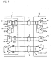
Damit die Anordnung zur seriellen Übertragung für möglichst viele Meßeinrichtungen einsetzbar ist, sind zusätzlich zu der Datenleitung 5 und Taktleitung 6 noch weitere Leitungen 16 zur Übertragung von analogen oder binären Zählsignalen einer inkrementalen Positionsmeßeinrichtung vorgesehen (Figur 7). Somit ist es möglich, parallel zu der absoluten Meßwertübertragung auf der Datenleitung 5 auch die Zählsignale auf der Leitung 16 zur Verarbeitungseinheit 4 zu senden. In Figur 7 ist auch ersichtlich, daß die bidirektionale Übertragung von Daten (Meßwerte und Parameter) zwischen der Meßeinrichtung 1 und der Verarbeitungseinheit 4 mit Signalpegeln nach RS485 (Differenzsignale) synchron zu einem von der Verarbeitungseinheit 4 vorgegebenen Taktsignal (CLOCK) erfolgt. Die Taktfrequenz liegt dabei zwischen 100KHz und 2MHz.In order that the arrangement for serial transmission can be used for as many measuring devices as possible, in addition to the
Wie bereits erwähnt, ermöglicht der Speicher 9 in der Meßeinrichtung 1 sowohl dem Kunden als auch dem Hersteller der Meßeinrichtung 1, Parameter abzuspeichern und auszulesen. Vorteilhaft ist es, wenn der Speicher 9 in mehrere Bereiche aufgeteilt ist:
- I. Speicherbereich für Parameter des Kunden
- II. Speicherbereich für Parameter des Meßsystem-Herstellers
- III. Speicherbereich für Korrekturwerte.
- I. Storage area for parameters of the customer
- II. Memory area for parameters of the measuring system manufacturer
- III. Memory area for correction values.
Der Speicherbereich des Meßsystem-Herstellers ist schreibgeschützt. Die einzelnen Speicherbereiche werden durch den Code "Memory Range Select" unterschieden.The memory area of the measuring system manufacturer is write-protected. The individual memory areas are distinguished by the code "Memory Range Select".
Die Speicher können folgendermaßen belegt werden:The memories can be occupied as follows:
Der Wert wird vom Nullpunkt des Meßsystemes 1 subtrahiert.The value is subtracted from the zero point of the
Diese Parameter können durch die Herstellung fest vorgegebene Daten beinhalten, aber zusätzlich auch Informationen über den Betriebszustand sowie über Betriebsparameter.These parameters may include fixed data by manufacturing, but also information about the operating state and operating parameters.
Gibt die Version an, nach welcher der SpeicherSpecifies the version according to which the memory is
Angabe der Größe der einzelnen Bereiche des Speichers 9.Indication of the size of the individual areas of the
Gibt die Anzahl der Takte zur Übertragung eines Meßwertes (Datenwort) an.Specifies the number of clocks to transmit a measured value (data word).
Gibt an, ob ein inkrementales Längen- oder Winkelmeßsystem mit oder ohne abstandscodierten Referenzmarken bzw. ob ein Singietum- oder Muttiturn-Codedrehgeber verwendet wird.Specifies whether an incremental length or angle measurement system with or without distance-coded reference marks or whether a singleturn or minturn code encoder is used.
Gibt die Breite einer Signalperiode bei Längenmeßsystemen bzw. die Anzahl der Signalperioden pro Umdrehung bei Winkelmeßsystemen an.Specifies the width of a signal period in length measuring systems or the number of signal periods per revolution in angle measuring systems.
Bei Multiturn-Codewinkelmeßsystemen erfolgt die Angabe der unterscheidbaren Umdrehungen.For multiturn code angle measuring systems, the specification of the distinguishable revolutions takes place.
Bei Meßsystemen mit abstandscodierten Referenzmarken erfolgt hiermit die Angabe des Grundabstandes der zusammengehörigen Referenzmarken. Bei Meßsystemen ohne abstandscodierten Referenzmarken erfolgt hiermit die Angabe des Abstandes zwischen zwei benachbarten Referenzmarken.In the case of measuring systems with distance-coded reference marks, this specifies the basic distance of the associated reference marks. In the case of measuring systems without distance-coded reference marks, the distance between two adjacent reference marks is specified.
Gibt die Position der ersten Referenzmarke bezogen auf die Endlage an.Indicates the position of the first reference mark relative to the end position.
Gibt bei Längenmeßsystemen den Meßschritt an, der bei der seriellen Datenübertragung vom Meßsystem ausgegeben wird. Bei Winkelmeßsystemen wird die Anzahl an Meßschritten pro Umdrehung angegeben.For length measuring systems, specifies the measuring step that is output by the measuring system during serial data transmission. For angle measuring systems, the number of measuring steps per revolution is specified.
Aufgetretene Fehler werden abgespeichert. Ist ein Bit beispielsweise ungleich Null, so wird bei der Übertragung von Meßwerten nach Figur 3 das Alarm-Bit gesetzt. Eine Alarm-Meldung kann auch zur Not-Abschaltung eines Antriebes verwendet werden.Errors that have occurred are saved. If, for example, a bit is not equal to zero, the alarm bit is set when transmitting measured values according to FIG. An alarm message can also be used for emergency shutdown of a drive.
Werden Toleranzvorgaben für bestimmte interne Größen des Meßsystems überschritten, die zum Ausfall des Meßsystemes führen können, so werden diese in Form von Warnmeldungen abgespeichert und können auf Anforderung ausgelesen werden. Bei batteriebetriebenen Meßsystemen kann eine Warnmeldung beispielsweise das Wort "Batteriewechsel° sein. Warnungen ermöglichen daher eine vorbeugende Wartung.If tolerances for certain internal sizes of the measuring system are exceeded, which can lead to failure of the measuring system, these are stored in the form of warning messages and can be read out on request. For example, in the case of battery-operated measuring systems, a warning message may be the word "battery replacement." Warnings therefore allow for preventative maintenance.
- 1. Anzahl der Korrekturwerte bezogen auf die Meßlänge1. Number of correction values related to the measuring length
- 2. Anzahl der Korrekturwerte für Signal-Abweichungen wie Signalamplituden, Phasenversatz sowie Nullpunkt-Abweichungen.2. Number of correction values for signal deviations such as signal amplitudes, phase offset and zero point deviations.
- 3. Anzahl der Korrekturwerte für Oberwellen.3. Number of harmonic correction values.
- 4. Anzahl der zu korrigierenden Oberwellen.4. Number of harmonics to be corrected.
- 5. Korrekturwerte zu 1.5. Correction values to 1.
- 6. Korrekturwerte zu 2.6. Correction values for 2.
- 7. Korrekturwerte zu 3.7. Correction values to 3.
Selbstverständlich liegt es im Rahmen der Erfindung, auch andere Parameter im Speicher 9 für die Verarbeitungseinheit 4 zur Verfügung zu stellen. Bei der Inbetriebnahme erfolgt eine Anpassung der Verarbeitungseinheit 4 durch Übernahme der notwendigen Parameter vom Meßsystem 1 über die Datenleitung 5.Of course, it is within the scope of the invention to provide other parameters in the
Die Bereiche des Speichers 9 können softwaremäßig aufgeteilt sein, es ist aber auch möglich, daß der Speicher 9 aus mehreren einzelnen Speicherbaueinheiten besteht.The areas of the
Es ist offensichtlich, daß die erfindungsgemäße Anordnung folgende Vorteile aufweist:
- Einsatz für Code-Meßsysteme und inkrementale Meßsysteme,
- Minimierte Übertragungszeiten für den absoluten Positionswert. Bei Anwendungen im geschlossenen Regelkreis werden dadurch Totzeiten reduziert und ein verbessertes Regelverhalten erreicht,
- Bidirektionale Schnittstelle mit der Möglichkeit, sowohl für den Kunden als auch für den MeßsystemHersteller, Parameter im Meßsystem abspeichem und auslesen zu können (Vereinfachung der Inbetriebnahme),
- Unterstützung von Überwachungs- und Diagnosefunktionen der Verarbeitungseinheit,
- Bei absoluten Meßsystemen erfolgt grundsätzlich eine Übertragung vollständiger Absolutwerte im Dual-Code unabhängig von der Art der Bestimmung des absoluten Positionsmeßwertes, wodurch keine unterschiedliche Auswertung in der Verarbeitungseinheit erforderlich ist.
- Das Format zur Übertragung des Positionsmeßwertes ist in seiner Länge variabel und hängt vom jeweiligen Meßsystem ab. Die Festlegung der Anzahl der Takte und die Zuordnung des Positionsmeßwertes zu den Takten erfolgt durch den abzufragenden Inhalt des Speichers im Meßsystem.
- Application for code measuring systems and incremental measuring systems,
- Minimized transmission times for the absolute position value. In closed-loop applications, dead times are reduced and improved control behavior is achieved.
- Bidirectional interface with the possibility for both the customer and the measuring system manufacturer to be able to save and read parameters in the measuring system (simplification of the commissioning),
- Support of monitoring and diagnostic functions of the processing unit,
- In absolute measuring systems, in principle, a transmission of complete absolute values in the dual-code takes place independently of the type of determination of the absolute position measurement value, whereby no different evaluation in the processing unit is required.
- The format for transmitting the position measurement value is variable in length and depends on the respective measuring system. The determination of the number of clocks and the assignment of Positionsmeßwertes to the clocks is done by the queried content of the memory in the measuring system.
Wie aus den vorhergehenden Ausführungen ersichtlich ist, ist es besonders vorteilhaft, wenn der Takt von der Verarbeitungseinheit 4 vorgegeben wird. Hierdurch ist eine synchrone Datenübertragung gewährleistet.As can be seen from the preceding embodiments, it is particularly advantageous if the clock is predetermined by the processing unit 4. This ensures a synchronous data transmission.
Die Erfindung ist aber auch einsetzbar, wenn der Takt vom Meßsystem 1 vorgegeben wird. Hierbei wird über die Taktleitung 6 von der Verarbeitungseinheit 4 ein Anforderungssignal (Request) an das Meßsystem 1 gesendet. Daraufhin werden synchron zu einem internen Takt die Bits des Positionsmeßwertes seriell über die Datenleitung 5 zu der Verarbeitungseinheit 4 gesendet. Um auch hier eine zum Verarbeitungstakt der Verarbeitungseinheit 4 synchrone Übertragung sicherzustellen, kann der interne Taktgeber des Meßsystems 1 mit einer. Flanke des Anforderungssignals synchronisiert werden. Das Anforderungssignal kann auch über die Datenleitung 5 zum Meßsystem 1 gesendet werden.However, the invention can also be used when the clock is specified by the measuring
Die Erfindung ist bei Winkel- sowie Längenmeßeinrichtungen einsetzbar. Das Abtastprinzip ist nicht auf das lichtelektrische Prinzip beschränkt. Der Code zur Bildung des zu übertragenden Positionsmeßwertes kann in einer einzigen Spur (Kettencode) oder in mehreren Spuren auf einem oder auf mehreren Codeträgem vorgesehen sein.The invention can be used in angle and length measuring devices. The scanning principle is not limited to the photoelectric principle. The code for forming the position measurement value to be transmitted may be provided in a single track (chain code) or in several tracks on one or more code carriers.
Claims (17)
- Apparatus for serial transmission of data between a position measuring device (1) and a processing unit (4), wherein- the position measuring device (1) comprises a unit (2) in which a binary code word defining the absolute position is formed from the sensing signals of at least one sensing device (10);- the binary code word can be fed to an output unit (3) which causes bit-serial transmission of the code word over a data line (5) in response to a command (Status) from the processing unit (4);- the position measuring device (1) comprises a plurality of memory regions (8, 9);- specific parameters of the position measuring device (1) are stored in one memory region (9) and can likewise be transmitted serially over the said data line (5) to the processing unit (4), whereby the processing unit (4) can be matched to these parameters;- a further memory region (8) serves for decoding commands (Status) from the processing unit (4), these commands (Status) likewise being capable of being transmitted serially as binary data words over the said data line (5) to the position measuring device (1);- a clock source (15) is provided in the processing unit (4) and clock pulse sequences can be fed over a clock line (6) to the clock input of the output unit (3) and- the position measurement values and the parameters can be transmitted bitserially over the data line to the processing unit (4) in clock synchronism with the clock pulse sequence;- the formation and storage of the instantaneous absolute position measurement value in the position measuring device (1) is triggered on one clock flank of the clock pulse sequence and- after a computing time (tc) dependent on the scope of the computations, a start message (Start) can be transmitted from the position measuring device (1) to the processing unit (4), indicating that a valid position measurement value is present for transmission.
- Apparatus according to claim 1, characterized in that the information as to the clock number required for the transmission of the position measurement value is stored as a specific parameter in the storage region (9).
- Apparatus according to any of the preceding claims, characterized in that parameters of the position measuring device (1) are stored in one memory region (9) by the manufacturer of the position measuring device (1) and this memory region (9) cannot be written to by the user of the position measuring device (1).
- Apparatus according to any of the preceding claims, characterized in that at least one memory region (9) is provided in the position measuring device (1) with user-specific parameters, which can be transmitted over the data line (5).
- Apparatus according to any of the preceding claims, characterized in that at least one memory region (9) is provided in the position measuring device (1) with alarm and/or error messages, which can be read over the data line (5).
- Apparatus according to any of the preceding claims, characterized in that the signal on the data line (5) is at the LOW level in the rest state.
- A method of serial transmission of data between a position measuring device (1) and a processing unit (4), wherein- commands (Status) are transmitted bit serially as data words from the processing unit (4) to the position measuring device (1) and the position measuring device (1) is thereupon caused to execute a command (Status) and, in dependence on the command (Status) to send to the processing unit (4) a position measurement value as a binary data word or a parameter stored in the position measuring device (1) as a binary data word, whereby the processing unit (4) can be matched to this parameter, or the position measuring device (1) is caused to receive parameters from the processing unit (4) and to store them in a memory region (9);- the commands (Status), the parameters and the position measurement values are transmitted on a common data line (5) in clock synchronism;- the clock pulse sequence for the clock synchronous transmission is transmitted from the processing unit (4) to the position measuring device (1) over a clock line (6);- the formation and storage of the instantaneous absolute position measurement value is triggered in the position measuring device (1) on one clock flank of the clock pulse sequence and- after a computing time (tc) dependent on the scope of the computations, a start message (Start) is transmitted from the position measuring device (1) to the processing unit (4), indicating that a valid position measurement value is present for transmission.
- A method according to claim 7, characterized in that the processing unit (4) transmits each bit of the command (Status) in synchronism with a falling clock flank.
- A method according to claim 7 or 8, characterized in that the analog values of the sensing device (10) are stored in the unit (2) on a negative clock flank of the clock pulse sequence and the formation and storage of the instantaneous absolute position measurement values is triggered in the position measuring device (1).
- A method according to any of claims 7 to 9, characterized in that the start message (Start) is transmitted in synchronism with a positive clock flank after the computing time (tc).
- A method according to any of claims 7 to 10, characterized in that- after the start message (Start) an alarm message (Alarm) in the form of an alarm bit is transmitted to the processing unit (4), informing the processing unit (4) of an error function of the measuring device (1), and- the data word of the position measurement value is subsequently transmitted to the processing unit (4).
- A method according to any of the preceding claims 7 to 11, characterized in that the least significant bit is transmitted first in the bit-serial transmission of the position measurement value.
- A method according to any of the preceding claims 7 to 12, characterized in that a memory region (9) is provided in the position measuring device (1), in which error information is stored for the case of error or on overstepping predetermined tolerances, which information is read on request by the processing unit (4).
- A method according to any of the preceding claims 7 to 13, characterized in that a data word (CRC) for checking the transmitted position measurement value at the processing unit (4) is transmitted after the transmission of the position measurement value.
- A method according to claim 14, characterized in that the clock stops after the CRC transmission up to storage of a new position measurement value and a command (Status) is transmitted before each transmission of a position measurement value from the processing unit (4).
- A method according to any of the preceding claims 7 to 15, characterized in that a mode of operation can be selected in which the clock runs without interruption and in response to a command (Status) a plurality of position measurement values are transmitted to the processing unit (4) one after the other, without a command (Status) being transmitted in between at the request of the processing unit (4).
- A method according to any of claims 7 to 16, characterized in that- the information as to the clock number required for the transmission of a position measurement value is stored in the position measuring device (1);- this information is read by the processing unit (4)- the required number of clock pulses for the measured value transmission is made available from the processing unit (4) to the position measuring device (1).
Applications Claiming Priority (2)
| Application Number | Priority Date | Filing Date | Title |
|---|---|---|---|
| DE4342377A DE4342377B4 (en) | 1993-12-13 | 1993-12-13 | Arrangement and method for serial data transmission of a position measuring device |
| DE4342377 | 1993-12-13 |
Publications (3)
| Publication Number | Publication Date |
|---|---|
| EP0660209A1 EP0660209A1 (en) | 1995-06-28 |
| EP0660209B1 EP0660209B1 (en) | 1996-10-30 |
| EP0660209B2 true EP0660209B2 (en) | 2006-06-14 |
Family
ID=6504818
Family Applications (1)
| Application Number | Title | Priority Date | Filing Date |
|---|---|---|---|
| EP94119466A Expired - Lifetime EP0660209B2 (en) | 1993-12-13 | 1994-12-09 | Method and device for serial transmission of data between a position sensing means and a data processing unit |
Country Status (3)
| Country | Link |
|---|---|
| EP (1) | EP0660209B2 (en) |
| AT (1) | ATE144845T1 (en) |
| DE (2) | DE4342377B4 (en) |
Cited By (8)
| Publication number | Priority date | Publication date | Assignee | Title |
|---|---|---|---|---|
| DE102007041744A1 (en) | 2007-09-04 | 2009-03-12 | Tr Electronic Gmbh | Measuring transducer's i.e. rotary incremental encoder, data transmitting method for monitoring electric motor, involves switching data, signals, instructions and power supply from/to transducer on connection with reduced number of wires |
| DE102008027902A1 (en) | 2008-06-11 | 2009-12-17 | Dr. Johannes Heidenhain Gmbh | Device and method for serial data transmission between a position measuring device and a control unit |
| DE102008053105A1 (en) | 2008-10-24 | 2010-04-29 | Dr. Johannes Heidenhain Gmbh | Device and method for data transmission between a position measuring device and a subsequent electronics |
| DE102008054887A1 (en) | 2008-12-18 | 2010-07-01 | Dr. Johannes Heidenhain Gmbh | Device and method for automated recognition of an interface |
| DE102010038552A1 (en) | 2010-07-28 | 2012-02-02 | Dr. Johannes Heidenhain Gmbh | Device for manipulating interface signals |
| DE102011006300A1 (en) | 2011-03-29 | 2012-10-04 | Dr. Johannes Heidenhain Gmbh | Method and monitoring unit for checking position values |
| DE102012201170A1 (en) | 2012-01-27 | 2013-08-01 | Dr. Johannes Heidenhain Gmbh | Device for transmitting sensor data |
| DE102012205802A1 (en) | 2012-04-10 | 2013-10-10 | Dr. Johannes Heidenhain Gmbh | Device and method for transmitting energy and data between a control unit and a position measuring device |
Families Citing this family (36)
| Publication number | Priority date | Publication date | Assignee | Title |
|---|---|---|---|---|
| EP0790489B1 (en) | 1996-02-16 | 2000-05-17 | Dr. Johannes Heidenhain GmbH | Apparatus and method for switching between different operating characteristics of a sensor device |
| DE19727352A1 (en) * | 1996-07-10 | 1998-01-15 | Heidenhain Gmbh Dr Johannes | Position determining method for rotor drive |
| DE19711216C1 (en) * | 1997-03-18 | 1998-05-07 | Heidenhain Gmbh Dr Johannes | Transmitting data between position measuring device and analysis unit, e.g. in machine tool |
| DE19711218C1 (en) * | 1997-03-18 | 1998-04-09 | Heidenhain Gmbh Dr Johannes | Data transmission device for position measuring device |
| JP2000028393A (en) * | 1998-07-08 | 2000-01-28 | Canon Inc | Measuring unit, management unit, driving unit, driving system, and measuring device |
| DE19933963A1 (en) | 1999-07-20 | 2001-02-01 | Heidenhain Gmbh Dr Johannes | Method and arrangement for data transmission between different storage units of position measuring devices |
| EP1126248B2 (en) † | 2000-02-17 | 2012-10-17 | Dr. Johannes Heidenhain GmbH | Position measuring device as well as method for operating the same |
| JP4889855B2 (en) * | 2000-02-17 | 2012-03-07 | ドクトル・ヨハネス・ハイデンハイン・ゲゼルシヤフト・ミツト・ベシユレンクテル・ハフツング | Position measuring device |
| DE10030357A1 (en) | 2000-06-21 | 2002-01-17 | Heidenhain Gmbh Dr Johannes | Method and device for serial data transmission between a position measuring system and a processing unit |
| DE10030358A1 (en) * | 2000-06-21 | 2002-01-03 | Heidenhain Gmbh Dr Johannes | Method and device for serial data transmission between a position measuring system and a processing unit |
| DE10050392A1 (en) * | 2000-10-12 | 2002-04-18 | Heidenhain Gmbh Dr Johannes | Position measurement device converts mutually phase shifted analog sensing signals from scale sensing elements into multi-position amplitude-proportional code word applied to output unit |
| DE10055996A1 (en) | 2000-11-11 | 2002-05-23 | Heidenhain Gmbh Dr Johannes | Position measuring device and method for commissioning a position measuring device |
| US7031031B1 (en) | 2000-12-06 | 2006-04-18 | Dr. Johannes Heidenhain Gmbh | Position measuring system |
| DE10117194B4 (en) | 2001-04-05 | 2013-09-19 | Anton Rodi | Angle or displacement encoder |
| GB0111482D0 (en) * | 2001-05-10 | 2001-07-04 | Fast Technology Ag | Data transfer protocol |
| DE10123292B4 (en) * | 2001-05-13 | 2010-07-22 | Anton Rodi | sensor system |
| DE10125533B4 (en) * | 2001-05-23 | 2005-06-02 | Dr. Johannes Heidenhain Gmbh | Method for operating a position-measuring device and position-measuring device and evaluation unit for carrying out the method |
| DE10137835A1 (en) * | 2001-08-02 | 2003-02-20 | Siedle Horst Gmbh & Co Kg | Interface for serial transmission of digital data |
| JP4351162B2 (en) * | 2002-09-25 | 2009-10-28 | ドクトル・ヨハネス・ハイデンハイン・ゲゼルシヤフト・ミツト・ベシユレンクテル・ハフツング | Method for operating a position measuring device and a position measuring device suitable for this |
| ATE534887T1 (en) * | 2007-01-19 | 2011-12-15 | Sick Stegmann Gmbh | METHOD AND DEVICE FOR PARAMETERIZING A MEASURING DEVICE |
| EP2138916B1 (en) * | 2008-06-24 | 2014-05-07 | SICK STEGMANN GmbH | Position measuring system |
| WO2011030628A1 (en) * | 2009-09-09 | 2011-03-17 | 株式会社安川電機 | Interface circuit, inverter apparatus, inverter system and transmission/reception method |
| ES2461969T3 (en) * | 2011-03-22 | 2014-05-21 | Agie Charmilles Sa | Procedure and device for digital data transmission |
| DE102012201651A1 (en) | 2012-02-03 | 2013-08-08 | Dr. Johannes Heidenhain Gmbh | Position measuring device |
| DE102012218890A1 (en) | 2012-10-17 | 2014-04-17 | Dr. Johannes Heidenhain Gmbh | Absolute position measuring device |
| DE102013208629A1 (en) | 2013-05-10 | 2014-11-13 | Dr. Johannes Heidenhain Gmbh | Position measuring device |
| DE102013209019A1 (en) | 2013-05-15 | 2014-11-20 | Dr. Johannes Heidenhain Gmbh | Method for transmitting data between a position-measuring device and an associated processing unit, and position-measuring device therefor |
| DE102013219099A1 (en) | 2013-09-24 | 2015-03-26 | Dr. Johannes Heidenhain Gmbh | Absolute position measuring device |
| DE102013219277A1 (en) | 2013-09-25 | 2015-03-26 | Dr. Johannes Heidenhain Gmbh | Position measuring device and method for checking a working clock signal |
| DE102014204155A1 (en) | 2014-03-06 | 2015-09-10 | Dr. Johannes Heidenhain Gmbh | Device for signal transmission |
| DE102014212288A1 (en) | 2014-06-26 | 2015-12-31 | Dr. Johannes Heidenhain Gmbh | Device and method for generating a trigger signal in a position measuring device and position measuring device for this purpose |
| DE102014225867A1 (en) | 2014-12-15 | 2016-06-16 | Dr. Johannes Heidenhain Gmbh | Device and method for checking a working clock signal of a position-measuring device |
| FR3035495B1 (en) * | 2015-04-23 | 2017-05-26 | Meggitt (Sensorex) | SYSTEM FOR MEASURING THE DISPLACEMENTS OF A MOBILE ORGAN, IN PARTICULAR AN AIRCRAFT |
| DE102015208409A1 (en) | 2015-05-06 | 2016-11-10 | Dr. Johannes Heidenhain Gmbh | Apparatus and method for processing serial data frames |
| DE102016212115A1 (en) | 2016-07-04 | 2018-01-04 | Dr. Johannes Heidenhain Gmbh | Device and method for data transmission |
| DE102019213982A1 (en) | 2019-09-13 | 2021-03-18 | Dr. Johannes Heidenhain Gmbh | Device and method for synchronous serial data transmission |
Family Cites Families (7)
| Publication number | Priority date | Publication date | Assignee | Title |
|---|---|---|---|---|
| DE2758525B1 (en) * | 1977-12-28 | 1979-06-28 | Heidenhain Gmbh Dr Johannes | Measuring device with coded subdivision |
| DE3340946A1 (en) * | 1983-11-11 | 1985-05-23 | Siemens AG, 1000 Berlin und 8000 München | HANDLING DEVICE, IN PARTICULAR INDUSTRIAL ROBOTS, WITH AT LEAST ONE SENSOR |
| ATE32949T1 (en) * | 1984-07-13 | 1988-03-15 | Stegmann Uhren Elektro | ARRANGEMENT FOR SERIAL TRANSMISSION OF THE MEASURED VALUES OF AT LEAST ONE TRANSDUCER. |
| US4912476A (en) * | 1985-05-03 | 1990-03-27 | Unisys Corporation | Antenna interface common module |
| DE3910718A1 (en) * | 1989-04-03 | 1990-10-04 | Siemens Ag | MONITORING DEVICE WITH SWITCHING DEVICE |
| DE3936452A1 (en) * | 1989-11-02 | 1991-05-08 | Heidenhain Gmbh Dr Johannes | METHOD FOR ADAPTING A NUMERIC CONTROL TO MACHINE AND / OR MEASURING SYSTEM PARAMETERS |
| DE4129577C2 (en) * | 1991-09-06 | 1999-11-25 | Mueller Arnold Gmbh Co Kg | Measuring system for measuring the angle of rotation |
-
1993
- 1993-12-13 DE DE4342377A patent/DE4342377B4/en not_active Expired - Lifetime
-
1994
- 1994-12-09 DE DE59400945T patent/DE59400945D1/en not_active Expired - Lifetime
- 1994-12-09 EP EP94119466A patent/EP0660209B2/en not_active Expired - Lifetime
- 1994-12-09 AT AT94119466T patent/ATE144845T1/en not_active IP Right Cessation
Cited By (11)
| Publication number | Priority date | Publication date | Assignee | Title |
|---|---|---|---|---|
| DE102007041744A1 (en) | 2007-09-04 | 2009-03-12 | Tr Electronic Gmbh | Measuring transducer's i.e. rotary incremental encoder, data transmitting method for monitoring electric motor, involves switching data, signals, instructions and power supply from/to transducer on connection with reduced number of wires |
| DE102008027902A1 (en) | 2008-06-11 | 2009-12-17 | Dr. Johannes Heidenhain Gmbh | Device and method for serial data transmission between a position measuring device and a control unit |
| WO2009149966A1 (en) * | 2008-06-11 | 2009-12-17 | Dr. Johannes Heidenhain Gmbh | Device and method for the serial data transmission between a position measuring device and a control unit |
| DE102008053105A1 (en) | 2008-10-24 | 2010-04-29 | Dr. Johannes Heidenhain Gmbh | Device and method for data transmission between a position measuring device and a subsequent electronics |
| DE102008054887A1 (en) | 2008-12-18 | 2010-07-01 | Dr. Johannes Heidenhain Gmbh | Device and method for automated recognition of an interface |
| US10120359B2 (en) | 2008-12-18 | 2018-11-06 | Dr. Johannes Heidenhain Gmbh | Device and method for the automated detection of an interface |
| DE102008054887B4 (en) * | 2008-12-18 | 2021-03-25 | Dr. Johannes Heidenhain Gmbh | Device and method for the automated recognition of an interface |
| DE102010038552A1 (en) | 2010-07-28 | 2012-02-02 | Dr. Johannes Heidenhain Gmbh | Device for manipulating interface signals |
| DE102011006300A1 (en) | 2011-03-29 | 2012-10-04 | Dr. Johannes Heidenhain Gmbh | Method and monitoring unit for checking position values |
| DE102012201170A1 (en) | 2012-01-27 | 2013-08-01 | Dr. Johannes Heidenhain Gmbh | Device for transmitting sensor data |
| DE102012205802A1 (en) | 2012-04-10 | 2013-10-10 | Dr. Johannes Heidenhain Gmbh | Device and method for transmitting energy and data between a control unit and a position measuring device |
Also Published As
| Publication number | Publication date |
|---|---|
| EP0660209A1 (en) | 1995-06-28 |
| DE59400945D1 (en) | 1996-12-05 |
| EP0660209B1 (en) | 1996-10-30 |
| ATE144845T1 (en) | 1996-11-15 |
| DE4342377B4 (en) | 2010-08-12 |
| DE4342377A1 (en) | 1995-06-14 |
Similar Documents
| Publication | Publication Date | Title |
|---|---|---|
| EP0660209B2 (en) | Method and device for serial transmission of data between a position sensing means and a data processing unit | |
| EP0120196B1 (en) | Circuit arrangement for the optical display of variables | |
| DE69534349T2 (en) | Control unit with fail-safe function, automatic control system for trains and system using them | |
| EP2246984B1 (en) | Diagnosis apparatus for monitoring an analogue-digital conversion apparatus | |
| EP1327119B2 (en) | Position measuring device and a method for operating a position measuring device | |
| EP1923670B1 (en) | Position measuring device | |
| EP2223049B1 (en) | Method for the secure acquisition of multiple analog input signals, analog input circuit, and measuring sensor and measuring transducer having an analog input circuit of this type | |
| DE102014101945A1 (en) | Transmitter with monitoring function | |
| DE102004045849B4 (en) | Encoder with absolute signal processing and incremental signal output | |
| DE3687765T2 (en) | DIGITAL AUTOMATIC FLIGHT CONTROL SYSTEM. | |
| DE10392545B4 (en) | Electronic circuitry for error-proof analog-to-digital conversion of signals | |
| DE3309920A1 (en) | Motor vehicle | |
| DE19508834C2 (en) | Position measuring system | |
| EP1593971B1 (en) | Device and method for the verification of the functionality of an angular encoder | |
| WO2007101658A1 (en) | Method for recording input signal variations | |
| DE102008034318B4 (en) | Arrangement for evaluating the measured values of a transducer | |
| DE10063449B4 (en) | Controller with consistency monitoring of interrupts and a method for performing consistency monitoring of interrupts on a controller | |
| DE102017218054B4 (en) | Method for evaluating data from at least one wheel speed sensor and control unit | |
| DE102022110084B4 (en) | Determining the position of a first object relative to a second object | |
| DE10152216B4 (en) | Method and device for monitoring a bus system | |
| EP3296184B1 (en) | Device and method for standstill monitoring in vehicles, especially railway vehicles | |
| EP3091685B1 (en) | Device and method for processing of serial data frames | |
| EP0425897B1 (en) | Method for operating a control system | |
| EP2138916B1 (en) | Position measuring system | |
| DE2056774C (en) | Measuring arrangement for displaying aircraft measured values |
Legal Events
| Date | Code | Title | Description |
|---|---|---|---|
| PUAI | Public reference made under article 153(3) epc to a published international application that has entered the european phase |
Free format text: ORIGINAL CODE: 0009012 |
|
| AK | Designated contracting states |
Kind code of ref document: A1 Designated state(s): AT CH DE FR GB IT LI |
|
| 17P | Request for examination filed |
Effective date: 19951228 |
|
| GRAG | Despatch of communication of intention to grant |
Free format text: ORIGINAL CODE: EPIDOS AGRA |
|
| GRAH | Despatch of communication of intention to grant a patent |
Free format text: ORIGINAL CODE: EPIDOS IGRA |
|
| 17Q | First examination report despatched |
Effective date: 19960403 |
|
| GRAH | Despatch of communication of intention to grant a patent |
Free format text: ORIGINAL CODE: EPIDOS IGRA |
|
| ITF | It: translation for a ep patent filed | ||
| GRAA | (expected) grant |
Free format text: ORIGINAL CODE: 0009210 |
|
| AK | Designated contracting states |
Kind code of ref document: B1 Designated state(s): AT CH DE FR GB IT LI |
|
| REF | Corresponds to: |
Ref document number: 144845 Country of ref document: AT Date of ref document: 19961115 Kind code of ref document: T |
|
| REG | Reference to a national code |
Ref country code: CH Ref legal event code: NV Representative=s name: TROESCH SCHEIDEGGER WERNER AG |
|
| ET | Fr: translation filed | ||
| GBT | Gb: translation of ep patent filed (gb section 77(6)(a)/1977) |
Effective date: 19961030 |
|
| REF | Corresponds to: |
Ref document number: 59400945 Country of ref document: DE Date of ref document: 19961205 |
|
| PLBQ | Unpublished change to opponent data |
Free format text: ORIGINAL CODE: EPIDOS OPPO |
|
| PLBI | Opposition filed |
Free format text: ORIGINAL CODE: 0009260 |
|
| PLBF | Reply of patent proprietor to notice(s) of opposition |
Free format text: ORIGINAL CODE: EPIDOS OBSO |
|
| 26 | Opposition filed |
Opponent name: MAX STEGMANN GMBH ANTRIEBSTECHNIK - ELEKTRONIK Effective date: 19970729 |
|
| PLBF | Reply of patent proprietor to notice(s) of opposition |
Free format text: ORIGINAL CODE: EPIDOS OBSO |
|
| PLBF | Reply of patent proprietor to notice(s) of opposition |
Free format text: ORIGINAL CODE: EPIDOS OBSO |
|
| REG | Reference to a national code |
Ref country code: GB Ref legal event code: IF02 |
|
| PLAW | Interlocutory decision in opposition |
Free format text: ORIGINAL CODE: EPIDOS IDOP |
|
| APAC | Appeal dossier modified |
Free format text: ORIGINAL CODE: EPIDOS NOAPO |
|
| APAC | Appeal dossier modified |
Free format text: ORIGINAL CODE: EPIDOS NOAPO |
|
| APAA | Appeal reference recorded |
Free format text: ORIGINAL CODE: EPIDOS REFN |
|
| PLAB | Opposition data, opponent's data or that of the opponent's representative modified |
Free format text: ORIGINAL CODE: 0009299OPPO |
|
| APAH | Appeal reference modified |
Free format text: ORIGINAL CODE: EPIDOSCREFNO |
|
| APBU | Appeal procedure closed |
Free format text: ORIGINAL CODE: EPIDOSNNOA9O |
|
| PUAH | Patent maintained in amended form |
Free format text: ORIGINAL CODE: 0009272 |
|
| STAA | Information on the status of an ep patent application or granted ep patent |
Free format text: STATUS: PATENT MAINTAINED AS AMENDED |
|
| 27A | Patent maintained in amended form |
Effective date: 20060614 |
|
| AK | Designated contracting states |
Kind code of ref document: B2 Designated state(s): AT CH DE FR GB IT LI |
|
| REG | Reference to a national code |
Ref country code: CH Ref legal event code: AEN Free format text: AUFRECHTERHALTUNG DES PATENTES IN GEAENDERTER FORM |
|
| GBTA | Gb: translation of amended ep patent filed (gb section 77(6)(b)/1977) |
Effective date: 20060719 |
|
| ET3 | Fr: translation filed ** decision concerning opposition | ||
| PGFP | Annual fee paid to national office [announced via postgrant information from national office to epo] |
Ref country code: AT Payment date: 20081215 Year of fee payment: 15 |
|
| PG25 | Lapsed in a contracting state [announced via postgrant information from national office to epo] |
Ref country code: AT Free format text: LAPSE BECAUSE OF NON-PAYMENT OF DUE FEES Effective date: 20091209 |
|
| PGFP | Annual fee paid to national office [announced via postgrant information from national office to epo] |
Ref country code: DE Payment date: 20131220 Year of fee payment: 20 Ref country code: CH Payment date: 20131219 Year of fee payment: 20 Ref country code: GB Payment date: 20131219 Year of fee payment: 20 |
|
| PGFP | Annual fee paid to national office [announced via postgrant information from national office to epo] |
Ref country code: IT Payment date: 20131217 Year of fee payment: 20 |
|
| PGFP | Annual fee paid to national office [announced via postgrant information from national office to epo] |
Ref country code: FR Payment date: 20131220 Year of fee payment: 20 |
|
| REG | Reference to a national code |
Ref country code: DE Ref legal event code: R071 Ref document number: 59400945 Country of ref document: DE |
|
| REG | Reference to a national code |
Ref country code: CH Ref legal event code: PL |
|
| REG | Reference to a national code |
Ref country code: GB Ref legal event code: PE20 Expiry date: 20141208 |
|
| PG25 | Lapsed in a contracting state [announced via postgrant information from national office to epo] |
Ref country code: GB Free format text: LAPSE BECAUSE OF EXPIRATION OF PROTECTION Effective date: 20141208 |