JP4889855B2 - Position measuring device - Google Patents
Position measuring device Download PDFInfo
- Publication number
- JP4889855B2 JP4889855B2 JP2000397745A JP2000397745A JP4889855B2 JP 4889855 B2 JP4889855 B2 JP 4889855B2 JP 2000397745 A JP2000397745 A JP 2000397745A JP 2000397745 A JP2000397745 A JP 2000397745A JP 4889855 B2 JP4889855 B2 JP 4889855B2
- Authority
- JP
- Japan
- Prior art keywords
- position measuring
- measuring device
- scanning
- adjustment amount
- adjustment
- Prior art date
- Legal status (The legal status is an assumption and is not a legal conclusion. Google has not performed a legal analysis and makes no representation as to the accuracy of the status listed.)
- Expired - Fee Related
Links
Images
Abstract
Description
本発明は、位置測定装置及び位置測定装置を作動させる方法に関する。
【0001】
公知の位置測定装置は、一般に測定部面内にある測定部、及びこの測定部に対して相対運動する走査ユニットを有する。この走査ユニット側では、走査部材が走査面内に配置されている。位置に依存した複数の出力信号が、これらの走査要素によって−物理的な走査原理にしたがって−生成される。測定部面と走査面との間の距離は、以下で走査距離として示す。説明したこれらの測定部面つまりこの測定部とこの測定ユニットとの間の相対運動は、ここでは直線的でも回転的でもよい。
【0002】
数値制御式の工作機械で使用されるような、例えば、公知の光電式の又は誘導的で増分式の位置測定装置が、このような位置測定装置の事例として開示されている。光電式の位置測定システムでは、一般に相違する複数の光電式の構成要素が走査面内に配置されている。これらの構成要素は、相違する複数の変調した出力信号を生成するために使用される;そのため、光源も、適切な光検出器と同様に使用される。誘導的な位置測定装置の場合では、例えば扁平な複数の送信コイル及び受信コイル又は送信コイル若しくは受信コイルが、走査面内に配置されている。誘導的な位置測定装置に関しては、例えばドイツ連邦共和国特許出願公開第 197 51 853 号明細書に開示されている。
【0003】
取付け時に可能な限り精確に調節される必要のあるその都度の走査距離が、このような位置測定装置で重要な値を表す。このことは、測定動作中に生成される出力信号の十分に大きい信号の振幅を保証するために必要である。取付け時の走査距離の可能な限り精確な調節は、特にシステムが製造者側で既に完全に取付けられるのではなくて、購入者側で初めてそのシステムによって取付けられるシステムで必要である。一般に、これらの位置測定装置は、直線的なシステムの場合は開いた測定装置(offene Messsysteme)と呼ばれ、回転的なシステムの場合は組込み式の回転エンコーダ(Einbau-Drehgebern) と呼ばれる。
【0004】
既に、多数の機械的な調節補助部材が、可能な限り最適な走査距離に調節するために提唱されている。これらの各種の調節補助部材の欠点は、これらの補助部材がそれぞれ位置測定装置の特定の構造に対してしか適さず、それ故に汎用的に使用できない点にある。
【0005】
適切な走査距離のほかに、最適な作動状態に関するその他の値が、位置測定装置の動作中に重要である;これらの値も、作動開始時に可能な限り最適にする必要がある。
【0006】
本発明の課題は、位置測定装置の最適な作動状態を精確に調節可能な、この位置測定装置を作動させる可能な限り汎用的に使用可能な方法及び適切な位置測定装置を提供することにある。
【0007】
この課題は、請求項1の特徴に記載の位置測定装置によって解決される。
【0008】
本発明の方法と本発明の位置測定装置の好適な実施形は、それぞれの従属請求項中に記載されている解決手段から実現される。
【0009】
本発明の方法及び本発明の位置測定装置は、従来の解決手段と比較して多くの有利な効果を奏する。
【0010】
すなわち、本発明の方法は、その都度の位置測定装置の特別な機械構造に関連するのではなくて、これらの位置測定装置のいろいろな種類で汎用的に使用可能である。
【0011】
例えば調節された走査距離の再検査が視覚的に不可能な取付け状態(Anbauverhaeltnissen) の場合に、実際に調節された走査距離に関する信頼性の高い情報が、本発明の方法によって使用者に提供される。このとき、その使用者は、製造者が予め設定した走査距離を複数の適切な調節要素によって限定的に調節するだけで済む。
【0012】
出力信号を一定の信号振幅に制御する制御装置がそれぞれの位置測定装置内に既に設けられている場合、本発明の方法は特に有益であることが分かる。このとき、取付け時のその都度の実際の走査距離を表示するためには、この制御装置によって絶え間なく決定される調節量値が、再処理されるだけで済む。
【0013】
さらに、本発明の方法は、直線的な位置測定装置と回転的な位置測定装置の双方に使用可能である。同様に、この本発明の方法は、位置測定装置とむすびついて実現され得る。これらの位置測定装置は、いろいろな物理的な走査原理に基づく。同様に、いろいろな位置測定装置を本発明にしたがって構成することが明らかに可能である。
【0014】
さらに、その他の点では、走査距離のほかに、位置測定装置の全ての機能状態を本発明にしたがって最適にすることができる。
【0015】
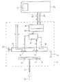
以下に、本発明の実施の形態のその他の有利な効果及び詳細を添付した図に基づいて説明する。この図は、本発明にしたがって構成された位置測定装置の概略的なブロック図である。
【0016】
位置測定装置は、図中には符号10で示されている。複数の要素だけがこの図によって概略的に示されている。これらの要素の機能が、本発明を説明するために重要である。誘導的で回転的な位置測定装置10を図示された実施の形態に基づいて説明する;しかし、明らかに、本発明は、直線的な位置測定装置と関連させてその他の物理的な走査原理に基づく位置測定装置において同様に使用することもできる。
【0017】
記された実施の形態の位置測定装置10は、向き合った2つの回転部材の相対位置を測定するために、例えば−図示しなかった−モータの1本の回転軸60の位置を測定するために使用される。
【0018】
位置測定装置10は、測定部12を有する。この測定部12は、部材担持体11上に配置されている。また、この部材担持体11は、回転軸60に連結されていて、かつ軸線50の周りを回転可能である。測定部面が、空間内のこの回転する測定部12の位置によって特定される。走査ユニット17が、この測定部12又はこの測定部面に対する走査距離Dで固定して配置されている。この走査ユニット17は、1つの又は多数の励磁要素18及び走査要素14等を有する。これらの励磁要素18及び走査要素14等は、回転する測定部12の走査時に位置に依存する出力信号A,Bを生成する。この場合、90°だけ位相のずれた一対の増分信号が、出力信号A,Bとして生成される。これらの出力信号A,Bは、順次電子機器によって再処理される。この順次電子機器20とは、例えば、工作機械の数値制御部である。
【0019】
図1中には、位置測定装置10によって生成された信号A,Bを順次電子機器20に伝送することに関連して、同期式のシリアル伝送の可能性が、1つの適切なインターフェース、並びに1本のデータバス30.2と1本のクロックバス30.1の形態の2本の信号伝送線によって示されている。しかし、その一方で、基本的には、位置測定装置10の生成されたアナログ式の出力信号A,Bを順次電子機器20に伝送することは、パラレルにも実現できる。同様に、明らかに、非同期式のデータ伝送等も、この位置測定装置10とこの順次電子機器20との間に使用され得る。
【0020】
本発明の位置測定装置10のこの実施形では、使用される測定部12は、異なる導電率の複数の部分領域から成る周期的な連続体から構成される。図中に同様に概略的にだけ示された励磁要素18は、扁平な励磁コイルとして形成されている。走査要素14は、扁平なセンサコイルとして形成されている。
【0021】
ここで、このような誘導的な位置測定装置10の測定部12と走査ユニット17の具体的な構成に関しては、本出願人のドイツ連邦共和国特許出願公開第 197 51 853 号明細書を補充的に参照されたい。しかしながら、本発明は、基本的に既に示したように、そこで開示した誘導的な位置測定装置の実施形にもこの物理的な走査原理にも限定されていない。すなわち、例えば光学的な又は光電的な位置測定装置も、本発明の範囲内で使用され得る。このとき、測定部12は、例えば異なる反射性の複数の部分領域を有する通常の照明測定部として形成され、光源が励磁要素の機能を果たし、公知のオプトエレクトロニクス式の検出要素が走査要素として設ける必要がある。
【0022】
さらに、本発明の位置測定装置10は、走査距離Dを調節する1つの又は多数の調節要素を有する。図中には、これらの調節要素のうちの1つが符号13で概略的に示されている。対応する調節要素13は、多様な形態で構成され得る;これに関しては、例えば本出願人のドイツ連邦共和国特許出願第 198 36 003 号明細書を参照されたい。この出願は、1つの適切な調節変形つまり調節に適した1つの位置決め手段を開示する。
【0023】
さらに、1つの制御装置14が、本発明の位置測定装置10の側面に配置されている。走査要素14の出力信号A,Bが、この制御装置14に入力される。さらに、この位置測定装置は、変換装置15と伝送装置16を有する。この伝送装置16は、既に述べたように同期式のシリアルインターフェイスとして構成されている。位置測定装置10と順次電子機器20との間のデータ転送は、伝送装置16とデータバス30.2とクロックバス30.1を経由して実行される。これらの個々の要素を機能させるには、以下の説明を参照されたい。
【0024】
ここで、適切な伝送装置つまり適切なシリアルインターフェースに関しては、例えば出願人によって商標EnDATで販売されたインターフェースを解析するか、さもなくばヨーロッパ特許第 0 660 209号明細書を参照されたい。
【0025】
以下に、本発明の方法を図中の概略的な表示に基づいて詳しく説明する。符号14で示された制御装置は、出力信号A,Bの信号振幅を一定の信号振幅に制御する。アナログ式のサイン状の又はコサイン状の出力信号A,Bの一定な信号振幅は、特に誤った測定を阻止する再処理時に必要である;これらの出力信号A,Bの信号振幅が一定でない場合は、例えば出力信号A,Bのさらなる信号の分割又は信号の補間時に、起こりうる誤差が位置測定中に発生する。しかしながら、様々な要因が、このような位置測定装置において測定動作中に振動振幅を変動させる。すなわち、例えば磁気的な又は誘導的な位置測定装置においては、走査距離Dが場合によっては変化したときに、信号振幅に望まない変動をもたらす;一方、光学的な位置測定装置では、測定部材の汚れが望まない信号振幅の減衰をもたらす。
【0026】
出力信号A,Bを一定な信号振幅に制御する制御装置14は、基本的には各種の位置測定装置に対して公知である。一般に、その都度の信号振幅が、対応する制御装置14内で実際値として算出され、1つのプリセットされた信号の目標値と比較される。そして、1つの調節量値が、その比較に基づいて決定される。この調節量値は、信号振幅の実際値を振幅の目標値に反復的に合わせるために必要である。これに関連した制御装置は公知である。これらの制御装置では、値R2 =A2 +B2 が、適切な回路によって位置測定装置10の位相のずれた2つの信号A=A0 * sin xt,B=B0 * cos xtから生成される。この値R2 は、信号振幅の実際の目安として、ひいては制御用の実際値として使用される。
【0027】
位置測定装置10の走査原理にしたがって、相違する調節量が、制御装置14によって出力されて、信号振幅を制御する。誘導的な位置測定装置10の場合では、送信コイルの通電量が、この制御装置14からの調節量Sとして適切に変化し得る。このことは、制御装置14と励磁要素18つまり送信コイルとの間の関係を通じて図中に具体的に説明されている。その代わりに、走査ユニットによって生成されるアナログ式の出力信号A,Bを増幅する増幅要素の増幅量を調節量として変化させることも可能である。これと同様に、光学的な位置測定装置では、光度が、調節量Sとして光源、すなわち光源電流に対応して変えられる。
【0028】
本発明では、出力信号A,Bを一定の信号振幅に制御するために必要になる調節量Sが、さらに走査距離Dを調節するためにも利用される。この場合、この目的に対する調節量Sの付加的な利用は、調節量値のその都度の値が実際の走査距離Dに対する直接的な目安を示すという認識に基づいている。この走査距離Dと調節量値とは、所定の範囲内では互いに比例する。すなわち、走査距離Dが大きく、かつ、信号振幅が比較的小さい場合は、調節量Sのより大きい値が発生する。この値は、制御部側で一定な信号振幅に再制御するために必要である。それとは反対に走査距離Dがより小さい場合は、信号振幅を制御するために必要なそれに応じたより小さい調節量値が発生する。
【0029】
さらに、調節量値Sは、位置測定装置の実際の機能状態に対する一般的な目安としても利用され得る。
【0030】
それ故に、制御に対して必要な調節量値は、本発明により、絶え間なく検出されて、シリアル伝送に適したデジタル信号に変えられるつまり変換される。この目的のために、本発明の位置測定装置10の調節量Sが、制御装置14によって概略的に示された変換装置15にも入力される。
【0031】
さらに、既に上述した伝送装置16は、変換装置15に付設されている。この伝送装置16は、例えば公知の同期式のシリアルインターフェースとして構成されている。このとき、適切に評価された調節量値が、この伝送装置16とデータバス30.2を経由して後続配置された順次電子機器20等に最終的に伝送される。ここでは、その調節量値は、規定された伝送プロトコル内で伝送される。この場合、その都度の調節量値が、予め設定されたビット幅で順次電子機器20に入力される。双方向に動作可能なデータバス30.2に加えて、この実施の形態では、伝送装置16と順次電子機器20との間のデータ転送を同期させる1本のクロックバス30.1がさらに配置されている。
【0032】
この場合、説明した様式の調節量値を順次電子機器20に伝送することは、本発明では重要でない。すなわち、別の伝送変形例も、本発明の範囲内で非常に良好に実現可能である。例えば、非同期式のシリアルデータ伝送等の範囲内で実現可能である。
【0033】
さらに、算出された調節量値を位置測定装置10の側面上で例えば実際の走査距離Dに相当する1つの値にすぐに変換すること、次いでこの値をデジタル信号として伝送することが考えられる。
【0034】
例えば通常のディスプレイとして構成されている表示装置21等が、順次電子機器20、例えば工作機械の数値制御部の側面上に設けられている。この場合、伝送されたばかりの調節量値も、いろいろなその他の情報のほかにこの表示装置21上に表示される。本発明の位置測定装置を取付けるため、適切な利用面が、例えば表示装置21によって使用者に提供され得る。調節量値や走査距離Dに関する情報等も、この利用面上で視覚表示される。
【0035】
次いで、その都度の使用者は、表示された調節量値に基づいて調節要素13を使用することによって位置測定装置10の取付け時に走査距離Dを特定して調節する。好ましくは、理想的な走査距離Dに関する所定の基準が、位置測定装置のその都度の製造者によってその使用者に予め知らされる。特に、この場合、例えば、所定の取付け許容範囲が、走査距離Dの値に対してプリセットすることができる。取付けは、この許容範囲内でする必要がある。システム全体が、実際の測定動作中にこの許容誤差を越えた時に突然停止することが絶対にないように、プリセットされた取付け許容誤差の限界値が、その都度作動可能範囲の限界から明らかに外れて選択されることが好ましいと確認されている。すなわち、例えば、作動可能範囲がD=[0.2mm;0.8mm] の場合、D=[0.45mm;0.55mm] の取付け許容範囲をプリセットすることが考えられる。
【0036】
使用者を支援する伝送された調節量値が、いろいろな方式で表示装置21上に表示されるか若しくは視覚表示されるか又はそれ以外の様式で知らされる。すなわち、調節量値を文字数字併用方式の値として直接的に表示することが可能である。さらに、調節量値を実際の走査距離に直接対応する値に変換することもできる。最終的には、調節量値をグラフ形式で、例えば適切な棒グラフ表示等で表示することも可能である。このとき、取付け許容範囲が、その調節量値の表示に応じてその位置測定装置の製造者によってプリセットされる必要が必ずある。
【0037】
さらに、既に述べたように、表示された調節量値が、位置測定装置の機能状態に対する一般的な目安として評価され得る。
【0038】
以上により、一連の実施の可能性が、本発明の範囲内で存在する。これらの実施の可能性は、要求に応じて実現され得る。
【図面の簡単な説明】
【図1】 本発明にしたがって構成された位置測定装置の概略的なブロック図である。
【符号の説明】
10 位置測定装置
11 部材担持体
12 測定部
13 調節要素
14 走査要素
15 変換装置
16 伝送装置
17 走査ユニット
18 励磁要素
20 順次電子機器
21 表示装置
30.1 クロックバス
30.2 データバス
A 出力信号
B 出力信号
S 調節量(値)
D 走査距離
50 軸線
60 回転軸The present invention relates to a position measuring device and a method of operating a position measuring device.
[0001]
A known position measuring apparatus generally has a measuring unit in the measuring unit plane and a scanning unit that moves relative to the measuring unit. On the scanning unit side, the scanning member is disposed in the scanning plane. A plurality of position-dependent output signals are generated by these scanning elements—in accordance with physical scanning principles. The distance between the measurement unit surface and the scanning surface is indicated as a scanning distance below. The relative movements between these measuring part surfaces, i.e. the measuring part and the measuring unit, described here may here be linear or rotational.
[0002]
For example, known photoelectric or inductive incremental position measuring devices, such as those used in numerically controlled machine tools, are disclosed as examples of such position measuring devices. In the photoelectric position measurement system, generally, a plurality of different photoelectric components are arranged in the scanning plane. These components are used to generate different modulated output signals; therefore, the light source is used as well as a suitable photodetector. In the case of an inductive position measuring device, for example, a plurality of flat transmitting coils and receiving coils or transmitting coils or receiving coils are arranged in the scanning plane. An inductive position measuring device is disclosed, for example, in DE 197 51 853.
[0003]
The respective scanning distance that needs to be adjusted as accurately as possible at the time of installation represents an important value in such a position measuring device. This is necessary to ensure a sufficiently large signal amplitude of the output signal generated during the measurement operation. The most accurate adjustment of the scanning distance at the time of installation is necessary especially for systems that are installed by the system for the first time on the purchaser side, rather than the system already being fully installed on the manufacturer side. In general, these position measuring devices are called open measuring devices (offene Messsysteme) for linear systems and built-in rotary encoders (Einbau-Drehgebern) for rotary systems.
[0004]
Already, a number of mechanical adjustment aids have been proposed to adjust to the optimum scanning distance possible. The disadvantage of these various adjustment aids is that each of these aids is only suitable for a specific structure of the position measuring device and therefore cannot be used universally.
[0005]
In addition to the appropriate scanning distance, other values for the optimal operating condition are important during operation of the position measuring device; these values should also be optimized as much as possible at the start of operation.
[0006]
It is an object of the present invention to provide a method and a suitable position measuring device that can be used as universally as possible to operate the position measuring device, which can accurately adjust the optimum operating state of the position measuring device. .
[0007]
This problem is solved by the position measuring device according to the features of claim 1.
[0008]
Preferred embodiments of the method according to the invention and the position measuring device according to the invention are realized from the solutions described in the respective dependent claims.
[0009]
The method of the present invention and the position measuring apparatus of the present invention have many advantageous effects compared with the conventional solutions.
[0010]
That is, the method of the present invention is not related to the special mechanical structure of the respective position measuring device but can be used universally with various types of these position measuring devices.
[0011]
Reliable information about the actually adjusted scan distance is provided to the user by the method of the present invention, for example, in the case of an installation where the re-examination of the adjusted scan distance is visually impossible (Anbauverhaeltnissen). The At this time, the user only needs to adjust the scanning distance preset by the manufacturer in a limited manner using a plurality of appropriate adjustment elements.
[0012]
It can be seen that the method according to the invention is particularly advantageous when a control device for controlling the output signal to a constant signal amplitude is already provided in each position measuring device. At this time, in order to display the actual scanning distance in each case at the time of installation, it is only necessary to re-process the adjustment amount value determined continuously by the control device.
[0013]
Furthermore, the method of the present invention can be used for both linear position measuring devices and rotary position measuring devices. Similarly, the method of the present invention can be implemented in conjunction with a position measuring device. These position measuring devices are based on various physical scanning principles. Similarly, it is obviously possible to construct various position measuring devices according to the invention.
[0014]
In addition, in addition to the scanning distance, all functional states of the position measuring device can be optimized according to the invention.
[0015]
Hereinafter, other advantageous effects and details of the embodiment of the present invention will be described with reference to the accompanying drawings. This figure is a schematic block diagram of a position measuring device constructed in accordance with the present invention.
[0016]
The position measuring device is indicated by
[0017]
The
[0018]
The
[0019]
In FIG. 1, in connection with the sequential transmission of the signals A, B generated by the
[0020]
In this embodiment of the
[0021]
Here, regarding the specific configurations of the measuring
[0022]
Furthermore, the
[0023]
Furthermore, one
[0024]
Here, as regards a suitable transmission device, ie a suitable serial interface, for example analyze the interface sold by the applicant under the trademark EnDAT, or else see EP 0 660 209.
[0025]
Hereinafter, the method of the present invention will be described in detail based on the schematic display in the figure. The control device indicated by
[0026]
The
[0027]
In accordance with the scanning principle of the
[0028]
In the present invention, the adjustment amount S required to control the output signals A and B to a constant signal amplitude is also used to adjust the scanning distance D. In this case, the additional use of the adjustment amount S for this purpose is based on the recognition that the respective value of the adjustment amount value represents a direct measure for the actual scanning distance D. The scanning distance D and the adjustment amount value are proportional to each other within a predetermined range. That is, when the scanning distance D is large and the signal amplitude is relatively small, a larger value of the adjustment amount S is generated. This value is necessary for re-controlling to a constant signal amplitude on the control unit side. On the other hand, if the scanning distance D is smaller, a smaller adjustment value corresponding to that required for controlling the signal amplitude is generated.
[0029]
Furthermore, the adjustment value S can also be used as a general measure for the actual functional state of the position measuring device.
[0030]
Therefore, the adjustment value required for the control is continuously detected and converted or converted into a digital signal suitable for serial transmission according to the invention. For this purpose, the adjustment amount S of the
[0031]
Further, the
[0032]
In this case, it is not important in the present invention to sequentially transmit the adjustment amount values in the manner described to the
[0033]
Furthermore, it is conceivable that the calculated adjustment amount value is immediately converted to one value corresponding to the actual scanning distance D, for example, on the side surface of the
[0034]
For example, a
[0035]
Then, each time the user specifies and adjusts the scanning distance D when the
[0036]
The transmitted adjustment value that assists the user is displayed on the
[0037]
Furthermore, as already mentioned, the displayed adjustment value can be evaluated as a general measure for the functional state of the position measuring device.
[0038]
From the above, a series of implementation possibilities exist within the scope of the present invention. These implementation possibilities can be realized on demand.
[Brief description of the drawings]
FIG. 1 is a schematic block diagram of a position measuring device configured in accordance with the present invention.
[Explanation of symbols]
DESCRIPTION OF
Claims (4)
この位置測定装置が、以下の要素を有し、
a)出力信号(A,B)を一定の信号振幅に制御し、かつ、所定の調節量に調節するために、この制御装置(19)によって絶え間なく必要な調節量(S)が算出される制御装置b)調節量をシリアル伝送に適したデジタル信号に変換する1つの変換装置(16)
かつ、
位置測定装置(10)は、誘導的な位置測定装置として構成されていて、この位置測定装置(10)は、走査面内に多数の送信コイルと受信コイル(14,18)を有し、出力信号(A,B)を一定の信号振幅に制御する制御装置(19)が、調節量として、この送信コイル(18)の通電量を変化させ、
表示装置(21)が、電子機器(20)の側面上に配置されていて、この表示装置(21)は、伝送されたデジタル信号を表示するために使用される位置測定装置。A position-dependent output signal by means of a plurality of scanning elements (14) defining scanning planes and a measuring section (12) which moves relative to these scanning elements (14) and defines a measuring plane. In the position measuring device that generates (A, B),
This position measuring device has the following elements:
a) In order to control the output signal (A, B) to a constant signal amplitude and adjust it to a predetermined adjustment amount, the control device (19) constantly calculates the necessary adjustment amount (S). Control device b) One converter (16) for converting the adjustment amount into a digital signal suitable for serial transmission
And,
The position measuring device (10) is configured as an inductive position measuring device, and this position measuring device (10) has a number of transmitting coils and receiving coils (14, 18) in the scanning plane, and outputs them. The control device (19) that controls the signals (A, B) to a constant signal amplitude changes the energization amount of the transmission coil (18) as an adjustment amount,
A display device (21) is disposed on the side surface of the electronic device (20), and the display device (21) is a position measuring device used for displaying a transmitted digital signal.
Applications Claiming Priority (4)
| Application Number | Priority Date | Filing Date | Title |
|---|---|---|---|
| DE2000107255 DE10007255A1 (en) | 2000-02-17 | 2000-02-17 | Work piece ejector for single/multistage press e.g. screws, rivets, etc. has ejector peg charged by pivoted ejector lever |
| DE10007255:9 | 2000-02-17 | ||
| DE10055488A DE10055488A1 (en) | 2000-02-17 | 2000-11-09 | Position measuring device and method for operating a position measuring device |
| DE10055488:1 | 2000-11-09 |
Publications (3)
| Publication Number | Publication Date |
|---|---|
| JP2001227987A JP2001227987A (en) | 2001-08-24 |
| JP2001227987A5 JP2001227987A5 (en) | 2008-02-14 |
| JP4889855B2 true JP4889855B2 (en) | 2012-03-07 |
Family
ID=26004386
Family Applications (1)
| Application Number | Title | Priority Date | Filing Date |
|---|---|---|---|
| JP2000397745A Expired - Fee Related JP4889855B2 (en) | 2000-02-17 | 2000-12-27 | Position measuring device |
Country Status (1)
| Country | Link |
|---|---|
| JP (1) | JP4889855B2 (en) |
Families Citing this family (1)
| Publication number | Priority date | Publication date | Assignee | Title |
|---|---|---|---|---|
| DE102016224012A1 (en) * | 2016-12-02 | 2018-06-07 | Dr. Johannes Heidenhain Gmbh | Position measuring device and method for operating a position measuring device |
Family Cites Families (10)
| Publication number | Priority date | Publication date | Assignee | Title |
|---|---|---|---|---|
| JPS61159101A (en) * | 1984-10-19 | 1986-07-18 | コルモーゲン コーポレイション | Position and speed sensor |
| JPS6312915A (en) * | 1986-07-03 | 1988-01-20 | Yamaha Corp | Detection signal processing circuit for encoder |
| JPH0236313A (en) * | 1988-07-26 | 1990-02-06 | Fanuc Ltd | Gap adjusting method for magnetic encoder |
| JP3196447B2 (en) * | 1993-09-14 | 2001-08-06 | 株式会社島津製作所 | Scanning probe microscope |
| DE4342377B4 (en) * | 1993-12-13 | 2010-08-12 | Dr. Johannes Heidenhain Gmbh | Arrangement and method for serial data transmission of a position measuring device |
| JP2710549B2 (en) * | 1994-03-10 | 1998-02-10 | 鹿島建設株式会社 | Gap tracking type magnetic length measuring device |
| JPH0914997A (en) * | 1995-06-29 | 1997-01-17 | Mitsutoyo Corp | Photoelectric encoder |
| DE19642199A1 (en) * | 1996-10-12 | 1998-04-16 | Heidenhain Gmbh Dr Johannes | Control device and method for testing position-dependent scanning signals |
| JP4001989B2 (en) * | 1996-11-29 | 2007-10-31 | ドクトル・ヨハネス・ハイデンハイン・ゲゼルシヤフト・ミツト・ベシユレンクテル・ハフツング | Scanning member of position measuring device |
| DE19836003A1 (en) * | 1998-08-08 | 2000-02-10 | Heidenhain Gmbh Dr Johannes | Method for mounting a position measuring device and positioning means for mounting |
-
2000
- 2000-12-27 JP JP2000397745A patent/JP4889855B2/en not_active Expired - Fee Related
Also Published As
| Publication number | Publication date |
|---|---|
| JP2001227987A (en) | 2001-08-24 |
Similar Documents
| Publication | Publication Date | Title |
|---|---|---|
| EP1619476B1 (en) | Encoder and signal adjustment method for the same | |
| EP1577645A1 (en) | Optical encoder | |
| US8466646B2 (en) | Apparatus and method for determining angular position | |
| JP2009121958A (en) | Rotary encoder and brushless motor | |
| NO842324L (en) | AUTOMATIC, DYNAMIC ERROR COMPENSATOR | |
| US10378991B2 (en) | Angle-measuring device and method for operating an angle-measuring device | |
| EP0826138A1 (en) | Scale reading apparatus | |
| JPH11514091A (en) | Positioning method and measurement system suitable for it | |
| US6031613A (en) | System and method for measuring the angular position of a rotatably positionable object | |
| KR20020059029A (en) | Apparatus for measuring absolute angle and method thereof | |
| US6591220B1 (en) | Method and apparatus for measuring angles and/or distances | |
| WO2002004895A2 (en) | Optical position sensor and position determination method | |
| US6806461B2 (en) | Position measuring device and method for operation of a position measuring device | |
| JP4703059B2 (en) | Photoelectric encoder | |
| US20050002032A1 (en) | Non-contact optical polarization angle encoder | |
| JP4889855B2 (en) | Position measuring device | |
| JP4999856B2 (en) | Position measurement system | |
| JP2009515177A5 (en) | ||
| EP1116331A1 (en) | Precision position encoder using coarse position indicator | |
| US20030095257A1 (en) | Non-contact optical polarization angle encoder | |
| JP2007040988A (en) | Magnetic field modulating angle measuring device and operating method | |
| JP7420525B2 (en) | Position-measuring devices and methods of operating position-measuring devices | |
| US20100076586A1 (en) | Positioning apparatus | |
| JP2009210374A (en) | Encoder and light receiving unit | |
| US20050052179A1 (en) | Method and device for preparing a sensor signal of a position sensor for transmission to an evaluation unit |
Legal Events
| Date | Code | Title | Description |
|---|---|---|---|
| A521 | Written amendment |
Free format text: JAPANESE INTERMEDIATE CODE: A523 Effective date: 20071221 |
|
| A621 | Written request for application examination |
Free format text: JAPANESE INTERMEDIATE CODE: A621 Effective date: 20071221 |
|
| RD04 | Notification of resignation of power of attorney |
Free format text: JAPANESE INTERMEDIATE CODE: A7424 Effective date: 20100517 |
|
| A131 | Notification of reasons for refusal |
Free format text: JAPANESE INTERMEDIATE CODE: A131 Effective date: 20100720 |
|
| A521 | Written amendment |
Free format text: JAPANESE INTERMEDIATE CODE: A523 Effective date: 20101019 |
|
| A131 | Notification of reasons for refusal |
Free format text: JAPANESE INTERMEDIATE CODE: A131 Effective date: 20110222 |
|
| A521 | Written amendment |
Free format text: JAPANESE INTERMEDIATE CODE: A523 Effective date: 20110513 |
|
| A131 | Notification of reasons for refusal |
Free format text: JAPANESE INTERMEDIATE CODE: A131 Effective date: 20110712 |
|
| A521 | Written amendment |
Free format text: JAPANESE INTERMEDIATE CODE: A523 Effective date: 20110805 |
|
| TRDD | Decision of grant or rejection written | ||
| A01 | Written decision to grant a patent or to grant a registration (utility model) |
Free format text: JAPANESE INTERMEDIATE CODE: A01 Effective date: 20111122 |
|
| A01 | Written decision to grant a patent or to grant a registration (utility model) |
Free format text: JAPANESE INTERMEDIATE CODE: A01 |
|
| A61 | First payment of annual fees (during grant procedure) |
Free format text: JAPANESE INTERMEDIATE CODE: A61 Effective date: 20111214 |
|
| R150 | Certificate of patent or registration of utility model |
Ref document number: 4889855 Country of ref document: JP Free format text: JAPANESE INTERMEDIATE CODE: R150 Free format text: JAPANESE INTERMEDIATE CODE: R150 |
|
| FPAY | Renewal fee payment (event date is renewal date of database) |
Free format text: PAYMENT UNTIL: 20141222 Year of fee payment: 3 |
|
| R250 | Receipt of annual fees |
Free format text: JAPANESE INTERMEDIATE CODE: R250 |
|
| R250 | Receipt of annual fees |
Free format text: JAPANESE INTERMEDIATE CODE: R250 |
|
| R250 | Receipt of annual fees |
Free format text: JAPANESE INTERMEDIATE CODE: R250 |
|
| R250 | Receipt of annual fees |
Free format text: JAPANESE INTERMEDIATE CODE: R250 |
|
| R250 | Receipt of annual fees |
Free format text: JAPANESE INTERMEDIATE CODE: R250 |
|
| R250 | Receipt of annual fees |
Free format text: JAPANESE INTERMEDIATE CODE: R250 |
|
| LAPS | Cancellation because of no payment of annual fees |