DE102010038552A1 - Device for manipulating interface signals - Google Patents

Device for manipulating interface signals Download PDF

Info

Publication number
DE102010038552A1
DE102010038552A1 DE102010038552A DE102010038552A DE102010038552A1 DE 102010038552 A1 DE102010038552 A1 DE 102010038552A1 DE 102010038552 A DE102010038552 A DE 102010038552A DE 102010038552 A DE102010038552 A DE 102010038552A DE 102010038552 A1 DE102010038552 A1 DE 102010038552A1
Authority
DE
Germany
Prior art keywords
interface
din
data
signal
dout
Prior art date
Legal status (The legal status is an assumption and is not a legal conclusion. Google has not performed a legal analysis and makes no representation as to the accuracy of the status listed.)
Withdrawn
Application number
DE102010038552A
Other languages
German (de)
Inventor
Dr. Kreuzer Stephan
Dr. Mayer Elmar
Udo Ollert
Current Assignee (The listed assignees may be inaccurate. Google has not performed a legal analysis and makes no representation or warranty as to the accuracy of the list.)
Dr Johannes Heidenhain GmbH
Original Assignee
Dr Johannes Heidenhain GmbH
Priority date (The priority date is an assumption and is not a legal conclusion. Google has not performed a legal analysis and makes no representation as to the accuracy of the date listed.)
Filing date
Publication date
Application filed by Dr Johannes Heidenhain GmbH filed Critical Dr Johannes Heidenhain GmbH
Priority to DE102010038552A priority Critical patent/DE102010038552A1/en
Priority to ES11164538T priority patent/ES2570169T3/en
Priority to EP11164538.8A priority patent/EP2413554B1/en
Priority to JP2011151584A priority patent/JP5876240B2/en
Priority to US13/188,240 priority patent/US9768990B2/en
Priority to CN201110213249.7A priority patent/CN102346718B/en
Publication of DE102010038552A1 publication Critical patent/DE102010038552A1/en
Withdrawn legal-status Critical Current

Links

Images

Classifications

    • HELECTRICITY
    • H04ELECTRIC COMMUNICATION TECHNIQUE
    • H04LTRANSMISSION OF DIGITAL INFORMATION, e.g. TELEGRAPHIC COMMUNICATION
    • H04L25/00Baseband systems
    • H04L25/38Synchronous or start-stop systems, e.g. for Baudot code
    • H04L25/40Transmitting circuits; Receiving circuits
    • H04L25/45Transmitting circuits; Receiving circuits using electronic distributors
    • GPHYSICS
    • G05CONTROLLING; REGULATING
    • G05BCONTROL OR REGULATING SYSTEMS IN GENERAL; FUNCTIONAL ELEMENTS OF SUCH SYSTEMS; MONITORING OR TESTING ARRANGEMENTS FOR SUCH SYSTEMS OR ELEMENTS
    • G05B19/00Programme-control systems
    • G05B19/02Programme-control systems electric
    • G05B19/04Programme control other than numerical control, i.e. in sequence controllers or logic controllers
    • G05B19/042Programme control other than numerical control, i.e. in sequence controllers or logic controllers using digital processors
    • G05B19/0428Safety, monitoring
    • GPHYSICS
    • G05CONTROLLING; REGULATING
    • G05BCONTROL OR REGULATING SYSTEMS IN GENERAL; FUNCTIONAL ELEMENTS OF SUCH SYSTEMS; MONITORING OR TESTING ARRANGEMENTS FOR SUCH SYSTEMS OR ELEMENTS
    • G05B19/00Programme-control systems
    • G05B19/02Programme-control systems electric
    • G05B19/18Numerical control [NC], i.e. automatically operating machines, in particular machine tools, e.g. in a manufacturing environment, so as to execute positioning, movement or co-ordinated operations by means of programme data in numerical form
    • G05B19/406Numerical control [NC], i.e. automatically operating machines, in particular machine tools, e.g. in a manufacturing environment, so as to execute positioning, movement or co-ordinated operations by means of programme data in numerical form characterised by monitoring or safety
    • GPHYSICS
    • G05CONTROLLING; REGULATING
    • G05BCONTROL OR REGULATING SYSTEMS IN GENERAL; FUNCTIONAL ELEMENTS OF SUCH SYSTEMS; MONITORING OR TESTING ARRANGEMENTS FOR SUCH SYSTEMS OR ELEMENTS
    • G05B19/00Programme-control systems
    • G05B19/02Programme-control systems electric
    • G05B19/18Numerical control [NC], i.e. automatically operating machines, in particular machine tools, e.g. in a manufacturing environment, so as to execute positioning, movement or co-ordinated operations by means of programme data in numerical form
    • G05B19/414Structure of the control system, e.g. common controller or multiprocessor systems, interface to servo, programmable interface controller
    • GPHYSICS
    • G05CONTROLLING; REGULATING
    • G05BCONTROL OR REGULATING SYSTEMS IN GENERAL; FUNCTIONAL ELEMENTS OF SUCH SYSTEMS; MONITORING OR TESTING ARRANGEMENTS FOR SUCH SYSTEMS OR ELEMENTS
    • G05B23/00Testing or monitoring of control systems or parts thereof
    • G05B23/02Electric testing or monitoring
    • G05B23/0205Electric testing or monitoring by means of a monitoring system capable of detecting and responding to faults
    • G05B23/0218Electric testing or monitoring by means of a monitoring system capable of detecting and responding to faults characterised by the fault detection method dealing with either existing or incipient faults
    • G05B23/0256Electric testing or monitoring by means of a monitoring system capable of detecting and responding to faults characterised by the fault detection method dealing with either existing or incipient faults injecting test signals and analyzing monitored process response, e.g. injecting the test signal while interrupting the normal operation of the monitored system; superimposing the test signal onto a control signal during normal operation of the monitored system
    • HELECTRICITY
    • H04ELECTRIC COMMUNICATION TECHNIQUE
    • H04QSELECTING
    • H04Q9/00Arrangements in telecontrol or telemetry systems for selectively calling a substation from a main station, in which substation desired apparatus is selected for applying a control signal thereto or for obtaining measured values therefrom
    • HELECTRICITY
    • H04ELECTRIC COMMUNICATION TECHNIQUE
    • H04QSELECTING
    • H04Q2209/00Arrangements in telecontrol or telemetry systems
    • H04Q2209/40Arrangements in telecontrol or telemetry systems using a wireless architecture
    • H04Q2209/43Arrangements in telecontrol or telemetry systems using a wireless architecture using wireless personal area networks [WPAN], e.g. 802.15, 802.15.1, 802.15.4, Bluetooth or ZigBee
    • HELECTRICITY
    • H04ELECTRIC COMMUNICATION TECHNIQUE
    • H04QSELECTING
    • H04Q2209/00Arrangements in telecontrol or telemetry systems
    • H04Q2209/70Arrangements in the main station, i.e. central controller
    • H04Q2209/75Arrangements in the main station, i.e. central controller by polling or interrogating the sub-stations

Abstract

Die vorliegende Erfindung betrifft eine Vorrichtung zur Manipulation von Schnittstellensignalen, mit • einer Slave-Schnittstelle (12), die an eine Master-Schnittstelle (22) eines Steuergeräts (20) anschließbar ist, • einer Master-Schnittstelle (18), die an eine Slave-Schnittstelle (32) eines Messgeräts (30) anschließbar ist, • einer Schaltungsanordnung (15), der je Schnittstelle (12, 18) wenigstens ein Dateneingangsignal (DIN_S, DIN_M) zugeführt ist und die je Dateneingangssignal (DIN_S, DIN_M) zur jeweils anderen Schnittstelle (12, 18) ein korrespondierendes Datenausgangssignal (DOUT_M, DOUT_S) ausgibt, wobei die Schaltungsanordnung (15) wenigstens eine Manipulationseinheit (110, 120) umfasst, der ein Dateneingangssignal (DIN_S, DIN_M) und ein Ersatzdatensignal (DE_S, DE_M) zugeführt ist und die ein korrespondierendes Datenausgangssignal (DOUT_M, DOUT_S) ausgibt, sowie eine Protokolleinheit (100), der wenigstens ein protokollrelevantes Schnittstellensignal (DIN_S, DIN_M, TCLK_S) zugeführt ist und die anhand von Manipulationsregeln und mit dem wenigstens einen protokollrelevanten Schnittstellensignal (DIN_S, DIN_M, TCLK_S) empfangenen Informationen auswählt, wann die wenigstens eine Manipulationseinheit (110, 120) als Datenausgangssignal (DOUT_M, DOUT_S) das korrespondierende Dateneingangssignal (DIN_S, DIN_M) oder das Ersatzdatensignal (DE_S, DE_M) ausgibt.The invention relates to a device for manipulating interface signals, with • a slave interface (12) that can be connected to a master interface (22) of a control unit (20), • a master interface (18) that can be connected to a Slave interface (32) of a measuring device (30) can be connected, • a circuit arrangement (15), to which at least one data input signal (DIN_S, DIN_M) is supplied per interface (12, 18) and each for the data input signal (DIN_S, DIN_M) another interface (12, 18) outputs a corresponding data output signal (DOUT_M, DOUT_S), the circuit arrangement (15) comprising at least one manipulation unit (110, 120) which is supplied with a data input signal (DIN_S, DIN_M) and a replacement data signal (DE_S, DE_M) and which outputs a corresponding data output signal (DOUT_M, DOUT_S), and a protocol unit (100) which outputs at least one protocol-relevant interface signal (DIN_S, DIN_M, T CLK_S) and the information received based on manipulation rules and with the at least one protocol-relevant interface signal (DIN_S, DIN_M, TCLK_S) selects when the at least one manipulation unit (110, 120) as the data output signal (DOUT_M, DOUT_S) selects the corresponding data input signal (DIN_S, DIN_M) or the replacement data signal (DE_S, DE_M).

Description

Die Erfindung betrifft eine Vorrichtung zur Manipulation von Schnittstellensignalen nach Anspruch 1. Weiter betrifft die Erfindung ein Steuergerät mit einer Vorrichtung zur Manipulation von Schnittstellensignalen nach Anspruch 7.The invention relates to a device for manipulating interface signals according to claim 1. Furthermore, the invention relates to a control device with a device for manipulating interface signals according to claim 7.

In der Automatisierungstechnik werden vermehrt Messgeräte eingesetzt, die digitale Messwerte zur Verfügung stellen. Im Bereich der numerischen Steuerungen, die beispielsweise zur Steuerung von Werkzeugmaschinen eingesetzt werden, gilt das besonders für Positionsmessgeräte zur Messung von linearen oder rotatorischen Bewegungen. Positionsmessgeräte, die digitale (absolute) Messwerte generieren, werden als absolute Positionsmessgeräte bezeichnet.In automation technology, more and more measuring devices are used which provide digital measured values. In the field of numerical controls, which are used, for example, for controlling machine tools, this applies in particular to position measuring devices for measuring linear or rotary movements. Position measuring devices that generate digital (absolute) measured values are referred to as absolute position measuring devices.

Für die Übertragung der absoluten Positionswerte kommen hauptsächlich serielle Datenschnittstellen zum Einsatz, da diese mit nur wenigen Datenübertragungsleitungen auskommen und trotzdem hohe Datenübertragungsraten aufweisen. Besonders vorteilhaft sind hier die sogenannten synchron-seriellen Schnittstellen, die eine uni- oder bidirektionale Datenleitung und eine Taktleitung aufweisen. Die Übertragung von Datenpaketen über die Datenleitung erfolgt synchron zu einem Taktsignal auf der Taktleitung. In der Automatisierungstechnik hat sich eine Vielzahl von digitalen Standardschnittstellen durchgesetzt, populäre Vertreter für synchron-serielle Schnittstellen sind beispielsweise die EnDat-Schnittstelle der Anmelderin, eine weitere ist unter der Bezeichnungen SSI bekannt. Daneben sind auch noch asynchrone serielle Schnittstellen wie beispielsweise Hiperface verbreitet.For the transmission of the absolute position values mainly serial data interfaces are used, since they manage with only a few data transmission lines and nevertheless have high data transmission rates. Particularly advantageous here are the so-called synchronous-serial interfaces, which have a uni- or bidirectional data line and a clock line. The transmission of data packets over the data line is synchronous with a clock signal on the clock line. In automation technology, a variety of digital standard interfaces has prevailed, popular representatives for synchronous serial interfaces, for example, the EnDat interface of the applicant, another is known under the designations SSI. In addition, asynchronous serial interfaces such as Hiperface are also common.

Die SSI-Schnittstelle wird in der EP0171579A1 beschrieben. Es handelt sich hierbei um eine synchron-serielle Datenschnittstelle mit einer unidirektionalen Daten- und einer unidirektionalen Taktleitung. Das Auslesen von Positionswerten von einem Positionsmessgerät erfolgt hier synchron zu einem Taktsignal auf der Taktleitung.The SSI interface is in the EP0171579A1 described. It is a synchronous serial data interface with a unidirectional data line and a unidirectional clock line. The readout of position values from a position measuring device takes place here in synchronism with a clock signal on the clock line.

Die EP0660209B2 beschreibt dagegen die Grundlage der EnDat-Schnittstelle der Anmelderin. Bei dieser handelt es sich ebenfalls um eine synchron-serielle Schnittstelle, die jedoch neben der unidirektionalen Taktleitung eine bidirektionale Datenleitung aufweist. Dadurch ist eine Übertragung von Daten in beide Richtungen – von der numerischen Steuerung zum Positionsmessgerät und vom Positionsmessgerät zur numerischen Steuerung – möglich. Die Datenübertragung erfolgt auch hier synchron zu einem Taktsignal auf der Taktleitung.The EP0660209B2 on the other hand describes the basis of the Applicant's EnDat interface. This is also a synchronous-serial interface, which has a bidirectional data line in addition to the unidirectional clock line. This allows data to be transmitted in both directions - from the numerical control to the position measuring device and from the position measuring device to the numerical control. The data transmission also takes place here synchronously with a clock signal on the clock line.

Mittlerweile werden über digitale Messgeräteschnittstellen neben den reinen Nutzdaten, (z. B. bei Positionsmessgeräten die Positionswerte) auch noch Zusatzdaten übertragen, einige Beispiele hierfür sind:

  • • Geschwindigkeit
  • • Beschleunigung
  • • Temperatur im Messgerät
  • • Zweiter, unabhängig erzeugter Positionswert
  • • Statusinformationen (Warnsignale, Fehlersignale, ...)
In the meantime, additional data is transferred via digital measuring device interfaces in addition to the pure user data (eg for position measuring devices the position values), some examples are:
  • • speed
  • • acceleration
  • • Temperature in the meter
  • • Second, independently generated position value
  • • status information (warning signals, error signals, ...)

Besonders im Hinblick auf die Betriebssicherheit von Automatisierungsanlagen ist es notwendig, die Reaktion der Anlage auf Fehlerzustände, die sich in den zwischen Steuerung und Messgerät ausgetauschten Daten wiederspiegeln, zu testen. Hierzu ein Beispiel:
Die Steuerung fordert in definierten Zeitabständen über die digitale Messgeräteschnittstelle Positionswerte von einem Positionsmessgerät an. Die Positionswerte werden in Form von Datenpaketen zur Steuerung übertragen. Zur Überprüfung, ob es sich bei dem aktuellen Positionswert auch um einen tatsächlich neu gebildeten Positionswert handelt, enthält das Datenpaket noch einen zweiten Positionswert, der im Messgerät unabhängig vom ersten Positionswert gebildet wurde und zu diesem einen definierten mathematischen Zusammenhang aufweist. Beispielsweise unterscheiden sich die beiden Positionswerte durch einen Offset, der der Steuerung bekannt ist. In der Steuerung kann nun durch Vergleich der beiden Positionswerte ermittelt werden, ob der Offset tatsächlich vorhanden ist, oder nicht. Im ersten Fall wurden die Daten korrekt gebildet und übertragen, im zweiten Fall ist entweder im Messgerät oder auf der Übertragungsstrecke ein Fehler aufgetreten.
Especially with regard to the operational safety of automation systems, it is necessary to test the reaction of the system to fault conditions, which are reflected in the data exchanged between the control unit and the measuring device. Here is an example:
The controller requests position values from a position measuring instrument at defined time intervals via the digital measuring device interface. The position values are transmitted to the controller in the form of data packets. To check whether the current position value is also an actually newly formed position value, the data packet also contains a second position value, which was formed in the measuring device independently of the first position value and has a defined mathematical relationship to this. For example, the two position values differ by an offset known to the controller. In the control can now be determined by comparing the two position values, whether the offset is actually present or not. In the first case, the data were correctly formed and transmitted, in the second case an error has occurred either in the meter or on the transmission link.

Ob die Steuerung aber einen derartigen Fehler tatsächlich erkennt und richtig reagiert, ist in der Praxis, also bei einer real existierenden Anlage, nur sehr schwierig zu überprüfen. Theoretisch besteht natürlich die Möglichkeit, das Messgerät entsprechend zu manipulieren, bzw. die eingebauten Messgeräte durch manipulierte zu ersetzen. Spätestens dann, wenn mehrere Messgeräte, bzw. mehrere Ausfallsituationen getestet werden sollen, scheitert diese Vorgehensweise am hohen Aufwand.However, whether the controller actually recognizes such an error and reacts correctly is very difficult to check in practice, ie in a real existing system. Theoretically, of course, there is the possibility to manipulate the meter accordingly, or to replace the built-in measuring instruments by manipulated. At the latest when several measuring devices or several failure situations are to be tested, this procedure fails because of the high expense.

Es ist daher Aufgabe der Erfindung, eine Vorrichtung anzugeben, die eine einfache Diagnose ermöglicht.It is therefore an object of the invention to provide a device that allows easy diagnosis.

Diese Aufgabe wird gelöst durch eine Vorrichtung nach Anspruch 1. Vorteilhafte Details der Vorrichtung ergeben sich aus den von Anspruch 1 abhängigen Ansprüchen.This object is achieved by a device according to claim 1. Advantageous details of the device emerge from the claims dependent on claim 1.

Es wird nun eine Vorrichtung zur Manipulation von Schnittstellensignalen vorgeschlagen, mit

  • • einer Slave-Schnittstelle, die an eine Master-Schnittstelle eines Steuergeräts anschließbar ist,
  • • einer Master-Schnittstelle, die an eine Slave-Schnittstelle eines Messgeräts anschließbar ist,
  • • einer Schaltungsanordnung, der je Schnittstelle wenigstens ein Dateneingangsignal zugeführt ist und die je Dateneingangssignal zur jeweils anderen Schnittstelle ein korrespondierendes Datenausgangssignal ausgibt, wobei
die Schaltungsanordnung wenigstens eine Manipulationseinheit umfasst, der ein Dateneingangssignal und ein Ersatzdatensignal zugeführt ist und die ein korrespondierendes Datenausgangssignal ausgibt, sowie eine Protokolleinheit, der wenigstens ein protokollrelevantes Schnittstellensignal zugeführt ist und die anhand von Manipulationsregeln und mit dem wenigstens einen protokollrelevanten Schnittstellensignal empfangenen Informationen auswählt, wann die wenigstens eine Manipulationseinheit als Datenausgangssignal das korrespondierende Dateneingangssignal oder das Ersatzdatensignal ausgibt.A device for manipulating interface signals is proposed, with
  • A slave interface, which can be connected to a master interface of a control unit,
  • A master interface which can be connected to a slave interface of a measuring device,
  • A circuit arrangement, which is supplied to each interface at least one data input signal and outputs the data input signal to the respective other interface a corresponding data output signal, wherein
the circuit arrangement comprises at least one manipulation unit to which a data input signal and a substitute data signal are supplied and which outputs a corresponding data output signal, and a protocol unit which is supplied with at least one protocol-relevant interface signal and which selects information received based on manipulation rules and with the at least one protocol-relevant interface signal the at least one manipulation unit outputs as data output signal the corresponding data input signal or the substitute data signal.

Weiter wird diese Aufgabe gelöst durch ein Steuergerät nach Anspruch 7.Furthermore, this object is achieved by a control device according to claim 7.

Weitere Vorteile sowie Einzelheiten der vorliegenden Erfindung ergeben sich aus der nachfolgenden Beschreibung anhand der Figuren. Dabei zeigtFurther advantages and details of the present invention will become apparent from the following description with reference to FIGS. It shows
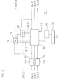
1 eine erfindungsgemäße Vorrichtung, die zwischen einem Steuergerät und einem Positionsmessgerät angeordnet ist, 1 a device according to the invention, which is arranged between a control device and a position measuring device,

2 ein Blockschaltbild einer Schaltungsanordnung, die in einer erfindungsgemäßen Vorrichtung enthalten ist, 2 a block diagram of a circuit arrangement which is contained in a device according to the invention,

3 eine vereinfachte Datenübertragungssequenz zur Veranschaulichung der Funktionsweise einer erfindungsgemäßen Vorrichtung, 3 a simplified data transmission sequence to illustrate the operation of a device according to the invention,

4 ein weiteres Ausführungsbeispiel, bei dem eine erfindungsgemäße Vorrichtung in ein Steuergerät integriert ist. 4 a further embodiment in which a device according to the invention is integrated into a control unit.

1 zeigt eine Vorrichtung 10 zur Manipulation von Schnittstellensignalen, die zwischen einem Steuergerät 20 und einem Messgerät 30 angeordnet ist. Das Steuergerät 20 kann ein beliebiges Gerät der Automatisierungstechnik oder Antriebstechnik sein, das wenigstens eine serielle Schnittstelle aufweist, die geeignet ist, mit einem an die Schnittstelle angeschlossenen Messgerät zu kommunizieren. Beispiele hierfür sind Positionsanzeigen, Numerische Steuerungen (NC) und Speicherprogrammierbare Steuerungen (SPS). In den folgenden Ausführungsbeispielen kommt als Steuergerät 20 stellvertretend eine Numerische Steuerung 20 zum Einsatz. Bei dem Messgerät handelt es sich insbesondere um ein Positionsmessgerät 30, beispielsweise zur Messung des Drehwinkels und/oder der Anzahl zurückgelegter Umdrehungen einer Welle W. 1 shows a device 10 for manipulating interface signals between a controller 20 and a meter 30 is arranged. The control unit 20 can be any device of automation technology or drive technology, which has at least one serial interface, which is suitable to communicate with a connected to the interface measuring device. Examples include position indicators, numerical controls (NC) and programmable logic controllers (PLCs). In the following embodiments comes as a control unit 20 representative of a numerical control 20 for use. The measuring device is in particular a position measuring device 30 For example, for measuring the rotation angle and / or the number of completed revolutions of a shaft W.

Die Vorrichtung 10 umfasst für den Datenaustausch mit der Numerischen Steuerung 20 eine Slave-Schnittstelle 12, die mittels eines ersten Schnittstellenkabels 13 mit einer Master-Schnittstelle 22 eines Schnittstellencontrollers 24 der Numerischen Steuerung 20 verbunden ist. Weiter umfasst die Vorrichtung eine Master-Schnittstelle 18, die mittels eines zweiten Schnittstellenkabels 19 mit einer Slave-Schnittstelle 32 des Positionsmessgerätes 30 verbunden ist. Zentrale Einheit der Vorrichtung 10 ist eine Schaltungsanordnung 15, die Schnittstellensignale verarbeitet. Der Aufbau der Schaltungsanordnung 15 wird unten in Verbindung mit 2 näher beschrieben.The device 10 includes for data exchange with numerical control 20 a slave interface 12 using a first interface cable 13 with a master interface 22 an interface controller 24 the numerical control 20 connected is. Furthermore, the device comprises a master interface 18 using a second interface cable 19 with a slave interface 32 of the position measuring device 30 connected is. Central unit of the device 10 is a circuit arrangement 15 which processes interface signals. The structure of the circuit arrangement 15 will be in contact with below 2 described in more detail.

Die Schnittstellenkabel und die Schnittstellen sind in üblicher Weise mit geeigneten Steckverbindern ausgestattet, so dass eine erfindungsgemäße Vorrichtung auch bei fertig installierten Automatisierungsanlagen, bzw. Werkzeugmaschinen, einfach zwischen die Numerische Steuerung 20 und das Positionsmessgerät 30 eingeschaltet werden kann, indem beispielsweise die Verbindung zwischen Master-Schnittstelle 22 der Numerischen Steuerung 20 und Slave-Schnittstelle 32 des Positionsmessgeräts 30 getrennt und je eine Verbindung zwischen Master-Schnittstelle 22 der Numerischen Steuerung 20 mit der Slave-Schnittstelle 12 der Vorrichtung 10, sowie der Slave-Schnittstelle 32 des Positionsmessgeräts 30 und der Master-Schnittstelle 18 der Vorrichtung 10 hergestellt wird. Der Vollständigkeit halber sei auch erwähnt, dass über die Schnittstellenkabel üblicherweise auch die Stromversorgung des Positionsmessgeräts 30 erfolgt und eine entsprechende Verbindung in der Vorrichtung 10 hergestellt wird (nicht dargestellt). Diese Stromversorgung kann auch für den Betrieb der Vorrichtung 10 herangezogen werden.The interface cables and the interfaces are equipped in the usual way with suitable connectors, so that a device according to the invention even in fully installed automation systems, or machine tools, simply between the numerical control 20 and the position measuring device 30 can be turned on, for example, the connection between master interface 22 the numerical control 20 and slave interface 32 of the position measuring device 30 separated and each one connection between master interface 22 the numerical control 20 with the slave interface 12 the device 10 , as well as the slave interface 32 of the position measuring device 30 and the master interface 18 the device 10 will be produced. For the sake of completeness, it should also be mentioned that the power supply of the position measuring device is usually also provided via the interface cables 30 takes place and a corresponding connection in the device 10 is produced (not shown). This power supply can also be used for the operation of the device 10 be used.

Die Schnittstellen können weiter in bekannter Weise Treiber- und Empfängerbausteine umfassen, beispielsweise um Schnittstellensignale, die als einfache, massebezogene digitale Signale in der Numerischen Steuerung 20, der Vorrichtung 10 und dem Positionsmessgerät 30 erzeugt und verarbeitet werden, in Signale umzuwandeln, die für die störsichere Übertragung über größere Entfernungen geeignet sind. Besonders verbreitet sind Treiber- und Empfängerbausteine, die eine differentielle Übertragung digitaler Signale nach dem bekannten RS-485-Standard erlauben. Ebenfalls bekannt und vorteilhaft ist die Umwandlung der digitalen Schnittstellensignale in optische Signale, die über Lichtwellenleiter übertragen werden.The interfaces may further comprise driver and receiver modules in a known manner, for example, interface signals serving as simple, ground-related digital signals in the numerical control 20 , the device 10 and the position measuring device 30 be generated and processed into signals that are suitable for interference-free transmission over long distances. Particularly common are driver and receiver modules, the differential transmission of digital signals according to the known RS-485 standard allow. Also known and advantageous is the conversion of the digital interface signals into optical signals that are transmitted via optical fibers.

Welche Daten vom Positionsmessgerät 30 angefordert, bzw. zum Positionsmessgerät 30 gesendet werden, bestimmt in der Numerischen Steuerung 20 eine Steuereinheit 26, die über eine Applikationsschnittstelle 27, 28 mit dem Schnittstellencontroller 24 verbunden ist. Der Schnittstellencontroller 24 dient hierbei quasi als Übersetzungseinheit, die Kommunikationsbefehle der allgemeinen Applikationsschnittstelle 27, 28 in Schnittstellensignale der speziellen Master-Schnittstelle 22 der Numerischen Steuerung 20 umwandelt. Die Bereitstellung angeforderter Daten, bzw. die Verarbeitung empfangener Daten erfolgt im Positionsmessgerät 30 in einer Messeinheit 34. Which data from the position measuring device 30 requested, or to the position measuring device 30 to be sent, determined in numerical control 20 a control unit 26 that have an application interface 27 . 28 with the interface controller 24 connected is. The interface controller 24 serves as a kind of translation unit, the communication commands of the general application interface 27 . 28 in interface signals of the special master interface 22 the numerical control 20 transforms. The provision of requested data or the processing of received data takes place in the position measuring device 30 in a measuring unit 34 ,

Bei der Steuereinheit 26 handelt es sich um eine programmgesteuerte Einheit, insbesondere basierend auf einem Mikrocontroller oder Mikroprozessor. Beispiele für Funktionen der Steuereinheit 26 sind das Auslesen und Anzeigen von Positionswerten, sowie das Kontrollieren komplexer Regelkreise, indem sie von Messgeräten, z. B. Positionsmessgeräten 30, Istwerte anfordert und aus diesen Sollwerte zur Steuerung von Antrieben ermittelt.At the control unit 26 it is a program-controlled unit, in particular based on a microcontroller or microprocessor. Examples of functions of the control unit 26 are the reading and displaying of position values, as well as the control of complex control loops, by measuring devices, eg. B. position measuring devices 30 , Actual values requested and determined from these setpoints for the control of drives.

Die Vorrichtung 10 ist im Grundzustand mit Vorteil transparent geschaltet, d. h. Eingangssignale, die bei einer der Schnittstellen 12, 18 der Vorrichtung 10 eintreffen, werden als korrespondierende Ausgangssignale bei der jeweils anderen Schnittstelle 12, 18 ausgegeben. Dadurch ist ein ungestörter Betrieb der von der Numerischen Steuerung 20 gesteuerten Anlage gewährleistet, auch wenn die Vorrichtung 10 vorhanden ist.The device 10 is in the ground state with advantage switched transparent, ie input signals at one of the interfaces 12 . 18 the device 10 arrive are as corresponding output signals at the other interface 12 . 18 output. This is an undisturbed operation of the numerical control 20 controlled system, even if the device 10 is available.

An der Vorrichtung 10 ist weiter eine Bedienschnittstelle 16 vorgesehen, an die mittels eines weiteren Schnittstellenkabels 45 eine Bedieneinheit 40 anschließbar ist. Die Bedienschnittstelle 16 kann sowohl zur Programmierung, als auch zur Steuerung der Funktionen der Schaltungsanordnung 15 dienen. Sie kann zwar vom selben Typ wie die Slave-Schnittstelle 12, bzw. die Master-Schnittstelle 18 sein, ist aber nicht darauf festgelegt. Einige Beispiele für die Ausführung der Bedienschnittstelle 16 wären I2C-, SPI-, oder JTAG-Schnittstelle. In der Praxis ist es besonders vorteilhaft, wenn als Bedieneinheit 40 ein handelsüblicher Personal Computer, insbesondere ein Laptop oder Notebook eingesetzt wird. Derartige Geräte verfügen standardmäßig über USB- oder Ethernet-Schnittstellen, die ebenfalls als Bedienschnittstelle 16 geeignet sind. Desweiteren sind auch drahtlose Schnittstellen verwendbar, etwa optisch nach dem IrDA-Standard oder via Funkstrecke nach dem Bluetooth- oder ZigBee-Standard. Anstelle einer separaten Bedieneinheit 40 besteht auch die Möglichkeit, die Vorrichtung 10 über eine zusätzliche Schnittstelle (nicht dargestellt) des Steuergeräts 20 zu bedienen. Dadurch werden ähnliche Vorteile wie bei dem weiter unten anhand von 4 beschriebenen Ausführungsbeispiel erzielt.At the device 10 is still a user interface 16 provided to the means of another interface cable 45 an operating unit 40 is connectable. The user interface 16 can both for programming, as well as for controlling the functions of the circuit arrangement 15 serve. Although it can be of the same type as the slave interface 12 , or the master interface 18 be, but not set. Some examples of the operation of the user interface 16 would be I2C, SPI, or JTAG interface. In practice, it is particularly advantageous if as a control unit 40 a commercial personal computer, in particular a laptop or notebook is used. Such devices have standard USB or Ethernet interfaces, which also serve as a user interface 16 are suitable. Furthermore, wireless interfaces can also be used, for example visually according to the IrDA standard or via radio link according to the Bluetooth or ZigBee standard. Instead of a separate control unit 40 there is also the possibility of the device 10 via an additional interface (not shown) of the control unit 20 to use. This will have similar advantages as in the below with reference to 4 achieved embodiment described.

Optional können in der Vorrichtung 10 noch Bedienelemente 50, beispielsweise als Tastenfeld ausgeführt, und eine Anzeigeeinheit 60 in Form eines mehrzeiligen Displays angeordnet sein, über die die Schaltungsanordnung 15 programmierbar und/oder bedienbar ist. Auf diese Weise können komplexe Bedienfunktionen, z. B. Aktivieren von Testfunktionen, Auswahl des Messgerätemodells, Version der Schnittstelle etc., direkt an der Vorrichtung 10 ausgeführt werden, so dass die Vorrichtung als autarkes Gerät betreibbar ist, das beispielsweise Servicepersonal zur Verfügung gestellt werden kann, um eine installierte Anlage bei einem Kunden zu überprüfen.Optionally, in the device 10 still controls 50 , executed, for example, as a keypad, and a display unit 60 be arranged in the form of a multi-line display, via which the circuit arrangement 15 programmable and / or operable. In this way, complex operating functions, eg. B. activation of test functions, selection of the meter model, version of the interface, etc., directly on the device 10 be executed so that the device is operable as a self-sufficient device that can be provided, for example, service personnel to check an installed system at a customer.

Im vorliegenden Beispiel handelt es sich bei der Master-Schnittstelle 22 der Numerischen Steuerung 20 um eine EnDat-Schnittstelle. Demzufolge erfolgt die physikalische Datenübertragung, wie in der Eingangs erwähnten EP0660209B2 beschrieben, gemäß dem RS-485-Standard in Form von Differenzsignalen über zwei Leitungspaare, wobei das erste Leitungspaar zur bidirektionalen Übertragung von Daten und das zweite Leitungspaar zur unidirektionalen Übertragung eines Taktsignals dient. Die Übertragung der Daten erfolgt synchron zum Taktsignal. Für diese Schnittstelle müssen intern drei Schnittstellensignale verwaltet werden, ein Taktsignal TCLK, ein Dateneingangssignal DIN und ein Datenausgangssignal DOUT. Die Einstellung der Datenrichtung, also ob das Datenausgangssignal aktiv ausgegeben wird, erfolgt über ein Freigabesignal OEN, das entsprechend dem Datenübertragungsprotokoll geschaltet wird.In this example, the master interface is 22 the numerical control 20 an EnDat interface. As a result, the physical data transmission occurs as mentioned in the introduction EP0660209B2 described according to the RS-485 standard in the form of differential signals over two pairs of lines, wherein the first line pair for bidirectional transmission of data and the second line pair for unidirectional transmission of a clock signal is used. The transmission of the data is synchronous to the clock signal. For this interface, three interface signals must internally be managed, a clock signal TCLK, a data input signal DIN and a data output signal DOUT. The setting of the data direction, ie whether the data output signal is actively output, via an enable signal OEN, which is switched according to the data transmission protocol.

Im Folgenden werden Slave-Schnittstellensignale, die zur Kommunikation der Slave-Schnittstelle 12 der Vorrichtung 10 mit der Master-Schnittstelle 22 der Numerischen Steuerung 20 dienen, als Slave-Dateneingangssignal DIN_S, Slave-Datenausgangsignal DOUT_S, Slave-Taktsignal TCLK_S und Slave-Freigabesignal OEN_S bezeichnet. Analog dazu erfolgt die Kommunikation der Master-Schnittstelle 18 der Vorrichtung 10 mit der Slave-Schnittstelle 32 des Positionsmessgeräts 30 über Master-Schnittstellensignale, insbesondere über ein Master-Dateneingangssignal DIN_M, ein Master-Datenausgangsignal DOUT_M, ein Master-Taktsignal TCLK_M und ein Master-Freigabesignal OEN_M. Korrespondierende Schnittstellensignale sind jeweils Slave-Dateneingangssignal DIN_S und Master-Datenausgangssignal DOUT_M, Slave-Taktsignal TCLK_S und Master-Taktsignal TCLK_M, sowie Master-Dateneingangssignal DIN_M und Slave-Datenausgangssignal DOUT_S.The following are slave interface signals used to communicate with the slave interface 12 the device 10 with the master interface 22 the numerical control 20 serve, designated as slave data input signal DIN_S, slave data output signal DOUT_S, slave clock signal TCLK_S and slave enable signal OEN_S. Analogously, the communication of the master interface takes place 18 the device 10 with the slave interface 32 of the position measuring device 30 via master interface signals, in particular via a master data input signal DIN_M, a master data output signal DOUT_M, a master clock signal TCLK_M and a master enable signal OEN_M. Corresponding interface signals are slave data input signal DIN_S and master data output signal DOUT_M, slave clock signal TCLK_S and master clock signal TCLK_M, as well as master data input signal DIN_M and slave data output signal DOUT_S.

2 zeigt ein Blockschaltbild einer Schaltungsanordnung 15. Einer zentralen Protokolleinheit 100 sind protokollrelevante Schnittstellensignale, also Signale, die zur Erkennung und Verarbeitung des Datenübertragungsprotokolls geeignet sind, zugeführt. Im vorliegenden Beispiel handelt es sich dabei um das Slave-Dateneingangssignal DIN_S, das Slave-Taktsignal TCLK_S und, wenn auch Antwortdaten des Positionsmessgeräts 30 verarbeitet werden sollen, das Master-Dateneingangssignal DIN_M. In Abhängigkeit von der aktuellen Datenrichtung, die sich aus dem Protokollablauf ergibt, erzeugt die Protokolleinheit 100 auch das Slave-Freigabesignal OEN_S und das Master-Freigabesignal OEN_M. Darüber hinaus gibt die Protokolleinheit 100 auch das Master-Taktsignal TCLK_M über die Master-Schnittstelle 18 zum Positionsmessgerät 30 aus. 2 shows a block diagram of a circuit arrangement 15 , A central protocol unit 100 are protocol relevant interface signals, ie signals that are suitable for the detection and processing of the data transmission protocol supplied. In the present example, these are the slave data input signal DIN_S, the slave clock signal TCLK_S and, although response data of the position measuring device 30 to be processed, the master data input signal DIN_M. Depending on the current data direction, which results from the protocol sequence, the protocol unit generates 100 also the slave enable signal OEN_S and the master enable signal OEN_M. In addition, there is the log unit 100 also the master clock signal TCLK_M via the master interface 18 to the position measuring device 30 out.

Das Slave-Dateneingangssignal DIN_S ist neben der Protokolleinheit 100 auch noch einer ersten Manipulationseinheit 110 zugeführt, die das Master-Datenausgangssignal DOUT_M ausgibt. Über einen von der Protokolleinheit 100 gesteuerten Umschalter 112 ist auswählbar, ob die erste Manipulationseinheit 110 als Master-Datenausgangssignal DOUT_M das Slave-Dateneingangssignal DIN_S oder ein von der Protokolleinheit 100 generiertes Slave-Ersatzdatensignal DE_S ausgibt. In anderen Worten bestimmt die Stellung des Umschalters 120 in der ersten Manipulationseinheit 110, ob die ursprünglich von der Numerischen Steuerung 20 gesendeten Daten, bzw. Befehle zum Positionsmessgerät 30 gelangen, oder von der Protokolleinheit 100 generierte Ersatzdaten. Auf diese Weise können einzelne Datenbits oder auch ganze Bitsequenzen manipuliert, bzw. ausgetauscht werden.The slave data input signal DIN_S is next to the protocol unit 100 even a first manipulation unit 110 which outputs the master data output DOUT_M. About one of the protocol unit 100 controlled switch 112 is selectable, whether the first manipulation unit 110 as master data output signal DOUT_M the slave data input signal DIN_S or one of the protocol unit 100 generated slave substitute data signal DE_S outputs. In other words, determines the position of the switch 120 in the first manipulation unit 110 whether the original of the numerical control 20 sent data, or commands to the position measuring device 30 or from the protocol unit 100 generated replacement data. In this way, individual data bits or entire bit sequences can be manipulated or exchanged.

In der entgegengesetzten Datenrichtung ist das Master-Dateneingangssignal DIN_M einer zweiten Manipulationseinheit 120 zugeführt, die das Slave-Datenausgangssignal DOUT_S ausgibt. In der zweiten Manipulationseinheit 120 bestimmt ein weiterer Umschalter 122, ob eben dieses Master-Dateneingangssignal DIN_M oder ein alternatives, in der Protokolleinheit 100 erzeugtes Master-Ersatzdatensignal DE_M als Slave-Datenausgangssignal DOUT_S ausgegeben wird. Auch hier ist nun eine bitweise Manipulation der Daten, die vom Positionsmessgerät 30 zur Numerischen Steuerung 20 gesendet werden, möglich.In the opposite data direction, the master data input signal DIN_M is a second manipulation unit 120 supplied, which outputs the slave data output signal DOUT_S. In the second manipulation unit 120 determines another switch 122 whether it is this master data input signal DIN_M or an alternative, in the protocol unit 100 generated master replacement data signal DE_M is output as slave data output signal DOUT_S. Here, too, is a bitwise manipulation of the data from the position measuring device 30 for numerical control 20 be sent, possible.

Die Protokolleinheit 100 ist mit Vorteil als zustandsgesteuerter Automat realisiert, der Informationen, insbesondere Befehle, die mit den protokollrelevanten Schnittstellensignalen von der Numerischen Steuerung 20 eintreffen, erkennt und in Abhängigkeit von diesen Informationen und nach vorgegebenen Manipulationsregeln eine Manipulation der Daten vornimmt. Sie arbeitet synchron zu einem Arbeitstaktsignal CLK, das entweder in der Schaltungsanordnung 15 erzeugt, oder dieser von außen zugeführt wird. Da die Schnittstellensignale, die aus Richtung der Numerischen Steuerung 20 bei der Schaltungsanordnung 15 ankommen, in diesem Beispiel konkret das Slave-Taktsignal TCLK_S und das Slave-Dateneingangssignal DIN_S, asynchron zum Arbeitstaktsignal CLK sind, ist es von Vorteil, diese bereits am Eingang der Schaltungsanordnung 15 mittels Synchronisationseinheiten 102, 104 mit dem Arbeitstaktsignal CLK zu synchronisieren. Dabei werden diese Signale lediglich zeitlich verzögert, bleiben ansonsten aber weitgehend unverändert. Da dadurch auch die Antwortdaten des Positionsmessgeräts 30 verzögert bei der Numerischen Steuerung 20 eintreffen, wirkt sich eine derartige Verzögerung auf die Numerische Steuerung 20 wie die Verwendung längerer Schnittstellenkabel 13, 19 aus. Um die Schnittstellensignale verarbeiten zu können, muss das Arbeitstaktsignal CLK die gleiche oder eine höhere Frequenz als die maximal zu erwartende Frequenz des Slave-Taktsignals TCLK_S aufweisen. Grundsätzlich gilt, je höher die Frequenz des Arbeitstaktsignals CLK ist, desto geringer ist die zeitliche Verzögerung der Schnittstellensignale. Bei einer maximalen Frequenz des Slave-Taktsignals TCLK_S von 10 MHz hat sich in der Praxis eine Frequenz des Arbeitstaktsignals CLK im Bereich von 40 bis 100 MHz als günstig erwiesen.The protocol unit 100 is implemented with advantage as a state-controlled automaton, the information, in particular commands, with the protocol-relevant interface signals from the numerical control 20 arrive, recognize and manipulate the data in accordance with this information and according to predetermined manipulation rules. It operates synchronously with a working clock signal CLK, either in the circuit arrangement 15 generated, or it is supplied from the outside. Because the interface signals coming from the direction of numerical control 20 in the circuit arrangement 15 arrive, in this example specifically the slave clock signal TCLK_S and the slave data input signal DIN_S, asynchronous to the work clock signal CLK, it is advantageous, this already at the input of the circuit 15 by means of synchronization units 102 . 104 to synchronize with the working clock signal CLK. These signals are only delayed in time, but otherwise remain largely unchanged. As a result, the response data of the position measuring device 30 delayed with the numerical control 20 arrive, such a delay affects the numerical control 20 like using longer interface cables 13 . 19 out. In order to be able to process the interface signals, the operating clock signal CLK must have the same or a higher frequency than the maximum expected frequency of the slave clock signal TCLK_S. In principle, the higher the frequency of the operating clock signal CLK, the lower the time delay of the interface signals. At a maximum frequency of the slave clock signal TCLK_S of 10 MHz, a frequency of the working clock signal CLK in the range of 40 to 100 MHz has proven to be favorable in practice.

Die Manipulationsregeln können beispielsweise fest im zustandsgesteuerten Automaten abgelegt sein. Besonders vorteilhaft ist es jedoch, einen Manipulationsspeicher 130 vorzusehen, dessen Inhalt über eine Kommunikationseinheit 140 programmierbar ist, die mit der Bedieneinheit 40 über die Bedienschnittstelle 16 über eine Anzahl von n Steuersignalen kommuniziert. Im Manipulationsspeicher 130 können sowohl Manipulationsregeln, als auch Ersatzdaten für die Erzeugung der Ersatzdatensignale DE_S, DE_M gespeichert werden. Auf diese Weise kann die Vorrichtung 10 flexibel an geänderte Anforderungen angepasst werden.The manipulation rules can for example be stored permanently in the state-controlled automaton. However, it is particularly advantageous to have a manipulation memory 130 to provide its content via a communication unit 140 is programmable with the control unit 40 via the user interface 16 communicates via a number of n control signals. In the manipulation memory 130 both manipulation rules and substitute data for the generation of the substitute data signals DE_S, DE_M can be stored. In this way, the device can 10 be flexibly adapted to changing requirements.

Die Bedienschnittstelle 16 kann darüber hinaus dazu genutzt werden, Modifikationen am Datenaustausch zwischen der Numerischen Steuerung 20 und dem Positionsmessgerät 30 erst freizugeben, bzw. Art und Umfang der Manipulationen festzulegen. Das kann beispielsweise über ein Computerprogramm erfolgen, das in der Bedieneinheit 40 ablauffähig ist und eine menügeführte Auswahl verschiedener Optionen anbietet.The user interface 16 can also be used to modify the data exchange between the numerical controller 20 and the position measuring device 30 first to release, or specify the nature and extent of the manipulation. This can be done for example via a computer program that in the control unit 40 is executable and offers a menu-driven selection of different options.

Als Schaltungsanordnung 15 kommt mit Vorteil ein programmierbarer Baustein zum Einsatz, beispielsweise ein FPGA (Field Programmable Gate Array). Derartige Bausteine können jederzeit neu programmiert werden und sind daher bestens geeignet, auf Änderungen und/oder Erweiterungen der Manipulationsmöglichkeiten einer erfindungsgemäßen Vorrichtung 10 zu reagieren. Ebenfalls besonders gut geeignet als Schaltungsanordnung 15 sind Mikrocontroller, da auch sie einfach umzuprogrammieren und an geänderte Bedingungen anzupassen sind. Die Programmierung der Schaltungsanordnung 15 kann beispielsweise ebenfalls über die Bedienschnittstelle 16 erfolgen.As a circuit arrangement 15 Advantageously, a programmable device is used, for example an FPGA (Field Programmable Gate Array). Such devices can be reprogrammed at any time and are therefore ideally suited to changes and / or extensions of the manipulation possibilities of a device according to the invention 10 to react. Also particularly well suited as a circuit arrangement 15 are Microcontrollers, as they are easy to reprogram and adapt to changing conditions. The programming of the circuit arrangement 15 can for example also via the user interface 16 respectively.

3 zeigt eine vereinfachte Datenübertragungssequenz zur Veranschaulichung der Funktionsweise einer erfindungsgemäßen Vorrichtung 10. Insbesondere wurde darauf verzichtet, geringe zeitliche Verzögerungen, hervorgerufen durch die Verarbeitung, bzw. Synchronisierung der Schnittstellensignale in der Schaltungsanordnung 100, darzustellen. Gezeigt ist die Übertragung eine s Positionsanforderungsbefehls von der Numerischen Steuerung 20 zum Positionsmessgerät 30, worauf das Positionsmessgerät 30 aktuelle Positionsdaten zur Numerischen Steuerung 20 sendet. Zur Erhöhung der Übertragungssicherheit ist zum einen der Positionsanforderungsbefehl redundant ausgelegt, insbesondere besteht er aus einem ersten Befehlsblock C1 und einem zweiten Befehlsblock C2, die beispielsweise aus je 3 Bits bestehen, wobei der zweite Befehlsblock C2 lediglich den ersten Befehlsblock C1 identisch oder invertiert wiederholt. Zum anderen sendet das Positionsmessgerät 30 als Antwort auf den Positionsanforderungsbefehl, wie oben bereits erwähnt, zwei Positionswerte POS1 und POS2, die den mathematischen Zusammenhang POS2 = POS1 + OFFSET zueinander aufweisen. Die Positionswerte POS1 und POS2 werden im Positionsmessgerät 30 unabhängig voneinander generiert, wodurch die Numerische Steuerung 20 durch Vergleich der Positionswerte POS1, POS2 mit dem bekannten mathematischen Zusammenhang feststellen kann, ob die Generierung und Übertragung der Positionswerte POS1, POS2 fehlerfrei war. Wird ein Fehler festgestellt, muss die Numerische Steuerung 20 definiert reagieren, beispielsweise durch Ausgeben einer Alarmmeldung oder durch Stillsetzen der Anlage („Sicherer Halt”), in der das Positionsmessgerät 30 betrieben wird. 3 shows a simplified data transmission sequence to illustrate the operation of a device according to the invention 10 , In particular, it has been dispensed with, small time delays caused by the processing or synchronization of the interface signals in the circuit arrangement 100 to represent. Shown is the transmission of a position request command from the numerical controller 20 to the position measuring device 30 , whereupon the position measuring device 30 current position data for numerical control 20 sends. In order to increase the transmission reliability, the position request command is designed to be redundant, in particular it consists of a first command block C1 and a second command block C2, each consisting of 3 bits, the second command block C2 repeating only the first command block C1 identically or inverted. On the other hand sends the position measuring device 30 in response to the position request command, as mentioned above, two position values POS1 and POS2 having the mathematical relationship POS2 = POS1 + OFFSET to each other. The position values POS1 and POS2 are in the position measuring device 30 generated independently of each other, eliminating the numerical control 20 by comparing the position values POS1, POS2 with the known mathematical relationship can determine whether the generation and transmission of the position values POS1, POS2 was error-free. If an error is detected, the numerical control must 20 defined, for example, by issuing an alarm message or by stopping the system ("safe stop"), in the position measuring device 30 is operated.

Als zusätzliche Maßnahme zur Erhöhung der Übertragungssicherheit können die Positionswerte POS1, POS2 jeweils durch einen CRC-Code abgeschlossen sein.As an additional measure for increasing the transmission reliability, the position values POS1, POS2 can each be completed by a CRC code.

Als Manipulationsregel für den oben beschriebenen Positionsanforderungsbefehl ist in der Vorrichtung 10 hinterlegt, dass an Stelle des tatsächlichen, vom Positionsmessgerät 30 gesendeten, zweiten Positionswerts POS2 ein alternativer, geänderter zweiter Positionswert POS2 zur Numerischen Steuerung 20 weitergeleitet werden soll. Die Manipulationsregel bestimmt somit, zu welchem Zeitpunkt die zweite Manipulationseinheit 120 umgeschaltet werden muss, um als Slave-Datenausgangssignal DOUT_S anstatt des Master-Dateneingangssignals DIN_M das Master-Ersatzdatensignal DE_M auszugeben. Auf welche Weise der zweite Positionswert POS2 geändert werden soll, kann ebenfalls in der Manipulationsregel festgelegt sein. Die Protokolleinheit stellt entsprechend dieser Vorgaben ein Master-Ersatzdatensignal DE_M bereit.The manipulation rule for the position request command described above is in the apparatus 10 deposited that in place of the actual, from the position measuring device 30 transmitted second position value POS2 an alternative, changed second position value POS2 for numerical control 20 should be forwarded. The manipulation rule thus determines at what time the second manipulation unit 120 must be switched to output as the slave data output DOUT_S instead of the master data input signal DIN_M the master replacement data signal DE_M. The way in which the second position value POS2 is to be changed can also be defined in the manipulation rule. The protocol unit provides a master replacement data signal DE_M in accordance with these specifications.

Die Manipulationsregel kann noch beliebige weitere Anweisungen enthalten, etwa, ob die Manipulation nur beim ersten Auftreten eines Befehls ausgeführt wird, oder mehrere Male, oder sogar jedes Mal, wenn dieser Befehl erkannt wird. Weiter kann festgelegt sein, ob die Manipulation immer gleich, oder jedes Mal anders, entsprechend einer Bildungsvorschrift für das Ersatzdatensignal DE_M, DE_S, erfolgt.The manipulation rule may include any further instructions, such as whether the manipulation is performed only on the first occurrence of a command, or multiple times, or even each time that command is detected. Furthermore, it can be determined whether the manipulation always takes place the same, or differently each time, according to an education specification for the substitute data signal DE_M, DE_S.

Es sei an dieser Stelle ausdrücklich darauf hingewiesen, dass Manipulationsregeln nicht zwingend Befehlen zugeordnet sein müssen, die im Rahmen des Datenübertragungsprotokolls von der Numerischen Steuerung 20 zum Positionsmessgerät 30 geschickt werden. Es kann vielmehr jeder beliebigen Information, die von der Numerischen Steuerung 20, oder auch vom Positionsmessgerät 30 bei der Vorrichtung 10, bzw. der Schaltungsanordnung 100 eintrifft, eine Manipulationsregel zugeordnet sein. Im einfachsten Fall kann bereits das Einsetzen des Taktsignals, also der Beginn einer Datenübertragung, als Information gewertet werden, der eine Manipulationsregel zugeordnet ist.It should be pointed out at this point that manipulation rules need not necessarily be assigned to commands that are part of the data transmission protocol of the numerical control 20 to the position measuring device 30 sent. Rather, it can be any information that comes from the numerical controller 20 , or from the position measuring device 30 at the device 10 , or the circuit arrangement 100 arrives to be associated with a manipulation rule. In the simplest case, the onset of the clock signal, that is to say the beginning of a data transmission, can already be regarded as information to which a manipulation rule is assigned.

Die erste Zeile der in 3 dargestellten Datenübertragungssequenz zeigt das von der Numerischen Steuerung 30 bei der Schaltungsanordnung 15 eintreffende Slave-Taktsignal TCLK_S, bzw. das (unter Vernachlässigung einer Verzögerung) von der Schaltungsanordnung 15 an das Positionsmessgerät 30 weitergeleitete Master-Taktsignal TCLK_M.The first line of in 3 shown data transmission sequence shows that of the numerical control 30 in the circuit arrangement 15 incoming slave clock signal TCLK_S, or (ignoring a delay) from the circuitry 15 to the position measuring device 30 forwarded master clock signal TCLK_M.

Die zweite Zeile zeigt das Slave-Dateneingangssignal DIN_S, das die Befehlsblöcke C1 und C2 umfasst, und, in diesem Beispiel unverändert, über die erste Manipulationseinheit 110 als Master-Datenausgangssignal DOUT_M in Richtung des Positionsmessgeräts 30 weitergeleitet wird.The second line shows the slave data input signal DIN_S, which comprises the command blocks C1 and C2, and, in this example, unchanged, via the first manipulation unit 110 as master data output signal DOUT_M in the direction of the position measuring device 30 is forwarded.

In der dritten Zeile ist das Master-Dateneingangssignal DIN_M dargestellt, das die Antwortdaten des Positionsmessgeräts 30 enthält, insbesondere die Positionswerte POS1 und POS2, ggf. abgeschlossen mit einem CRC-Code (nicht dargestellt).The third line shows the master data input signal DIN_M, which is the response data of the position measuring device 30 contains, in particular the position values POS1 and POS2, possibly completed with a CRC code (not shown).

Die vierte Zeile zeigt schließlich ein Master-Ersatzdatensignal DE_M, das von der Protokolleinheit 100 erzeugt wird und in diesem Beispiel zum Ersatz des vom Positionsmessgerät 30 gesendeten zweiten Positionswerts POS2 dient. Bei der Erzeugung des Master-Ersatzdatensignals DE_M ist natürlich zu beachten, ob ein CRC-Code erforderlich ist oder nicht.Finally, the fourth line shows a master replacement data signal DE_M, which is from the protocol unit 100 is generated and in this example to replace the position of the device 30 sent second position value POS2 is used. When generating the master substitute data signal DE_M, it should be noted, of course, whether a CRC code is required or not.

Das jeweils von der zweiten Manipulationseinheit 120 ausgewählte Datensignal (entweder das Master-Dateneingangssignal DIN_M oder das Master-Ersatzdatensignal DE_M) wird als Slave-Datenausgangssignal DOUT_S zur Numerischen Steuerung 20 weitergeleitet. The respectively from the second manipulation unit 120 selected data signal (either the master data input signal DIN_M or the master replacement data signal DE_M) is used as a slave data output signal DOUT_S for numerical control 20 forwarded.

Der zeitliche Ablauf gestaltet sich wie folgt:
Nach dem Aktivieren des Slave-Taktsignals TCLK_S findet zuerst eine Umschaltung der Datenrichtung statt. Unter der Annahme, dass im Ruhezustand das Slave-Freigabesignal OEN_S aktiv und das Master-Freigabesignal OEN_M passiv geschaltet ist, schaltet die Protokolleinheit 100 in einem ersten Umschaltzeitraum U1 zwischen den Zeitpunkten 11 und t2 zuerst das Slave-Freigabesignal OEN_S passiv und dann das Master-Freigabesignal OEN_M aktiv. Die Umschaltung erfolgt zeitlich gestaffelt, um Datenkollisionen zu vermeiden.
The timing is as follows:
After activating the slave clock signal TCLK_S, the data direction is first switched over. Assuming that in the idle state the slave enable signal OEN_S is active and the master enable signal OEN_M is passive, the protocol unit switches 100 in a first switching period U1 between times 11 and t2 first the slave enable signal OEN_S passive and then the master enable signal OEN_M active. Switching is staggered in order to avoid data collisions.

Ab dem Zeitpunkt t2 folgt die Übertragung des ersten Befehlsblocks C1, gefolgt, ab dem Zeitpunkt t3, vom zweiten Befehlsblock C2.From the time t2 follows the transmission of the first command block C1, followed, from the time t3, by the second command block C2.

Die Übertragung des zweiten Befehlsblocks C2 ist zum Zeitpunkt t4 beendet, die Protokolleinheit 100 kann nun durch Vergleich der Befehlsblöcke C1, C2 feststellen, ob die Übertragung des Befehls fehlerfrei war.The transmission of the second command block C2 is completed at time t4, the protocol unit 100 can now determine whether the transmission of the command was error-free by comparing the command blocks C1, C2.

Spätestens zum Zeitpunkt t4 hat die Protokolleinheit 100 ausreichend Informationen, um feststellen zu können, ob eine Manipulation von Schnittstellensignalen vorgenommen werden soll, d. h. ob für diesen Befehl, wie in diesem Beispiel, eine Manipulationsregel vorliegt. Die Manipulationsregel ist entweder in der Protokolleinheit 100 definiert, oder im Manipulationsspeicher 130 abgespeichert. Ebenso ist es möglich, dass diese Information der Protokolleinheit 100 von der Bedieneinheit 40 über Bedienschnittstelle 16 und Kommunikationseinheit 140 mitgeteilt wird.By the time t4 at the latest, the protocol unit 100 sufficient information to determine if any manipulation of interface signals should be made, ie if there is a manipulation rule for this command, as in this example. The manipulation rule is either in the protocol unit 100 defined, or in the manipulation memory 130 stored. It is also possible that this information of the protocol unit 100 from the control unit 40 via operator interface 16 and communication unit 140 is communicated.

Auf die Übertragung des Befehls folgt ab dem Zeitpunkt t4 bis zum Zeitpunkt t5 ein zweiter Umschaltzeitraum U2 in dem die Datenrichtung umgeschaltet wird, insbesondere schaltet die Protokolleinheit das Master-Freigabesignal OEN_M passiv und das Slave-Freigabesignal OEN_S aktiv.Following the transmission of the command, from time t4 to time t5, a second switching period U2 in which the data direction is switched follows, in particular the protocol unit activates the master enable signal OEN_M passive and the slave enable signal OEN_S active.

Ab dem Zeitpunkt t5 beginnt die Übertragung der Antwortdaten vom Positionsmessgerät 30 zur Numerischen Steuerung 20, wobei zuerst eine Startsequenz START gesendet wird, die beispielsweise aus einem Startbit, gefolgt von diversen Statusbits, die Rückschlüsse auf den Betriebszustand des Positionsmessgeräts 30 erlauben, besteht.From time t5, the transmission of the response data from the position measuring device begins 30 for numerical control 20 , wherein first a start sequence START is sent, which, for example, from a start bit, followed by various status bits, the conclusions about the operating state of the position encoder 30 allow, exists.

Auf die Startsequenz START folgend wird ab dem Zeitpunkt t6 das erste Positionswort POS1 übertragen.Following the start sequence START, the first position word POS1 is transmitted from the time t6.

Entsprechend der Manipulationsregel für den vorliegenden Befehl schaltet die Protokolleinheit 100 zum Zeitpunkt 17 das Schaltelement 122 in der zweiten Manipulationseinheit 120 um, so dass ab diesem Zeitpunkt das Master-Ersatzdatensignal DE_M, das von der Protokolleinheit 100 in Abhängigkeit von der Manipulationsregel bereitgestellt wird, anstelle des Master-Dateneingangssignals DIN_M als Slave-Datenausgangssignal DOUT_S zur Numerischen Steuerung 20 ausgegeben wird.According to the manipulation rule for the present command, the protocol unit switches 100 at the time 17 the switching element 122 in the second manipulation unit 120 um, so that from this point on the master replacement data signal DE_M, that of the protocol unit 100 is provided in response to the manipulation rule, instead of the master data input signal DIN_M as a slave data output signal DOUT_S for numerical control 20 is issued.

Zum Zeitpunkt t8 ist die Datenübertragung beendet und die Protokolleinheit 100 geht in den Ausgangszustand zurück.At time t8, the data transmission is complete and the protocol unit 100 returns to the initial state.

Wie das in Verbindung mit 3 beschriebene Beispiel für eine Manipulation des Datenverkehrs zwischen der Masterschnittstelle 22 einer Numerischen Steuerung 20 und der Slave-Schnittstelle eines Positionsmessgeräts 30 zeigt, bietet eine erfindungsgemäße Vorrichtung 10, bzw. eine Schaltungsanordnung 15 vielfältige Möglichkeiten, die Reaktion der Numerischen Steuerung 20 auf vermeintlich fehlerhafte, vom Positionsmessgerät 30 gesendete Daten zu prüfen. Besonders vorteilhaft ist es, dass hierfür weder die Numerische Steuerung 20, noch das Positionsmessgerät 30 verändert werden müssen.Like that in conjunction with 3 described example of a manipulation of data traffic between the master interface 22 a numerical control 20 and the slave interface of a position measuring device 30 shows offers a device according to the invention 10 , or a circuit arrangement 15 various possibilities, the reaction of numerical control 20 on supposedly faulty, from the position measuring device 30 to check sent data. It is particularly advantageous that this neither the numerical control 20 , nor the position gauge 30 have to be changed.

Einige weitere Beispiele für Manipulationen des Datenverkehrs sind:

  • • Wird anstatt eines zweiten Positionswerts POS2 als Zusatzinformation ein Temperaturwert, der die Temperatur im Positionsmessgerät angibt, übertragen, kann beispielsweise durch Austausch des tatsächlich gemessenen Temperaturwertes mit einem alternativen Temperaturwert eine Überhitzung des Positionsmessgeräts 30 vorgegeben und die Reaktion der Numerischen Steuerung 20 darauf geprüft werden.
  • • Ist die Zusatzinformation ein von Positionsänderungen abhängiger Wert, beispielsweise ein Geschwindigkeitswert, so kann durch dessen Manipulation geprüft werden, ob die Numerische Steuerung 20 eine Abweichung von einem Geschwindigkeitswert, der mit Hilfe von zwei aufeinanderfolgenden Positionswerten und der bekannten Zeit zwischen zwei Positionsabfragen in der Numerischen Steuerung 20 errechnet wird und dem im Positionsmessgerät 30 ermittelten Geschwindigkeitswert erkennt und entsprechend darauf reagiert.
  • • Durch Ändern einzelner Bits, beispielsweise im zweiten Befehlsblock C2, kann eine Störung der Datenübertragung zwischen Numerischer Steuerung 20 und Positionsmessgerät 30 simuliert werden.
  • • Werden Konfigurationsdaten von der Numerischen Steuerung 20 zum Positionsmessgerät 30 gesendet, kann durch deren Manipulation eine Fehlkonfiguration des Positionsmessgeräts 30 generiert werden.
  • • Ebenso können Daten, die in Speichereinheiten im Positionsmessgerät abgelegt sind (z. B. das sog. Elektronische Typenschild), wenn sie von der Numerischen Steuerung 20 angefordert werden, durch alternative Daten ersetzt werden und so beispielsweise ein anderer Messgerätetyp oder eine andere Messgeräteversion vorgetäuscht werden.
Some other examples of traffic manipulation are:
  • If, instead of a second position value POS2, a temperature value which indicates the temperature in the position measuring device is transmitted as additional information, it is possible, for example by replacing the actually measured temperature value with an alternative temperature value, to overheat the position measuring device 30 given and the reaction of the numerical control 20 be checked.
  • • If the additional information is a value dependent on position changes, for example a speed value, it can be checked by manipulating whether the numerical control 20 a deviation from a velocity value obtained by means of two consecutive position values and the known time between two position queries in the numerical control 20 is calculated and that in the position measuring device 30 detects detected speed value and reacts accordingly.
  • By changing individual bits, for example in the second command block C2, a disturbance of the data transfer between Numerical control 20 and position measuring device 30 be simulated.
  • • Become configuration data from the numerical controller 20 to the position measuring device 30 sent, can by manipulating a misconfiguration of the position measuring device 30 to be generated.
  • • Likewise, data stored in memory units in the position measuring device (eg the so-called electronic type plate) can be stored by the numerical control 20 be replaced with alternative data and thus, for example, a different type of meter or another version of the meter be faked.

4 zeigt ein weiteres Ausführungsbeispiel, bei dem eine erfindungsgemäße Vorrichtung 10 in ein Steuergerät, z. B. eine Numerische Steuerung 200 integriert ist. Die Bezugszeichen von Komponenten, die bereits in Verbindung mit dem Ausführungsbeispiel in 1 beschrieben wurden, wurden beibehalten. 4 shows a further embodiment in which a device according to the invention 10 in a control unit, for. B. a numerical control 200 is integrated. The reference numerals of components already used in connection with the embodiment in FIG 1 were retained.

Die Master-Schnittstelle 22, die der Schnittstellencontroller 24 der Numerischen Steuerung 200 bereitstellt, ist nun bereits im Gehäuse der Numerischen Steuerung 200 mit der Slave-Schnittstelle 12 der Vorrichtung 10 verbunden, im einfachsten Fall erfolgt die Verbindung korrespondierender Schnittstellensignale direkt, also ohne Steckverbinder und/oder Treiberbausteine. Die Master-Schnittstelle 18 der Vorrichtung 10 wird nun zur Master-Schnittstelle der Numerischen Steuerung 200, an die ein Messgerät 30, insbesondere ein Positionsmessgerät 30 angeschlossen werden kann.The master interface 22 that the interface controller 24 the numerical control 200 is now already in the housing of the numerical control 200 with the slave interface 12 the device 10 connected, in the simplest case, the connection of corresponding interface signals directly, ie without connectors and / or driver blocks. The master interface 18 the device 10 now becomes the master interface of the numerical control 200 to which a meter 30 , in particular a position measuring device 30 can be connected.

Zur Steuerung und ggf. Programmierung der Vorrichtung 10 ist die Bedienschnittstelle 16 jetzt mit einer zweiten Applikationsschnittstelle 210 der Steuereinheit 26 verbunden. Als zweite Applikationsschnittstelle 210 und Bedienschnittstelle 16 kommen vorzugsweise drahtgebundene Schnittstellen zum Einsatz. Besonders vorteilhaft ist es, wenn die Schnittstellenverbindung zwischen der zweiten Applikationsschnittstelle 210 und der Bedienschnittstelle 16 identisch zur Schnittstellenverbindung der Applikationsschnittstelle 27, 28 zwischen Steuereinheit 26 und Schnittstellencontroller 24 ist, da die Steuereinheit 26 üblicherweise bereits mehrere Applikationsschnittstellen bereitstellt und so für die Vorrichtung 10 eine Standardschnittstelle verwendet werden kann.For controlling and possibly programming the device 10 is the user interface 16 now with a second application interface 210 the control unit 26 connected. As a second application interface 210 and user interface 16 preferably wired interfaces are used. It is particularly advantageous if the interface connection between the second application interface 210 and the user interface 16 identical to the interface connection of the application interface 27 . 28 between control unit 26 and interface controller 24 is because the control unit 26 Usually already provides several application interfaces and so for the device 10 a standard interface can be used.

Der wesentliche Unterschied im Vergleich zum ersten Ausführungsbeispiel ist, dass die Vorrichtung 10 jetzt immer verfügbar ist. Somit ist es beispielsweise für den Betreiber einer Werkzeugmaschine zu jeder Zeit möglich, ein Selbsttestprogramm ablaufen zu lassen, das sicherheitsrelevante Funktionen überprüft, um festzustellen, ob die Anlage noch der geforderten Sicherheitsstufe genügt. Derartige Selbsttestprogramme können auch automatisiert gestartet werden, etwa in definierten Zeitintervallen oder zu Beginn eines neuen Bearbeitungsprogramms. Entsprechende Selbsttestprogramme können dem Betreiber einer von der Numerischen Steuerung 20 gesteuerten Anlage vom Hersteller zur Verfügung gestellt werden.The main difference compared to the first embodiment is that the device 10 now always available. Thus, it is for example possible for the operator of a machine tool at any time to run a self-test program that checks safety-related functions to determine whether the system still meets the required level of security. Such self-test programs can also be started automatically, for example at defined time intervals or at the beginning of a new machining program. Corresponding self-test programs may be the operator of one of the numerical control 20 controlled system provided by the manufacturer.

Mit Vorteil ist die Vorrichtung 10 als Erweiterungsmodul ausgeführt, mit dem eine Numerische Steuerung 200 auch nachträglich ausgestattet werden kann.Advantageous is the device 10 implemented as an expansion module, with a numerical control 200 can also be retrofitted.

Weiter besteht die Möglichkeit, den Schnittstellencontroller 24 und die Schaltungsanordnung 15 in einem einzigen Baustein, beispielsweise einem FPGA, ASIC oder Mikrocontroller zu realisieren.It is also possible to use the interface controller 24 and the circuit arrangement 15 in a single device, such as an FPGA, ASIC or microcontroller to realize.

ZITATE ENTHALTEN IN DER BESCHREIBUNG QUOTES INCLUDE IN THE DESCRIPTION

Diese Liste der vom Anmelder aufgeführten Dokumente wurde automatisiert erzeugt und ist ausschließlich zur besseren Information des Lesers aufgenommen. Die Liste ist nicht Bestandteil der deutschen Patent- bzw. Gebrauchsmusteranmeldung. Das DPMA übernimmt keinerlei Haftung für etwaige Fehler oder Auslassungen.This list of the documents listed by the applicant has been generated automatically and is included solely for the better information of the reader. The list is not part of the German patent or utility model application. The DPMA assumes no liability for any errors or omissions.

Zitierte PatentliteraturCited patent literature

  • EP 0171579 A1 [0004] EP 0171579 A1 [0004]
  • EP 0660209 B2 [0005, 0027] EP 0660209 B2 [0005, 0027]

Zitierte Nicht-PatentliteraturCited non-patent literature

  • RS-485-Standard [0021] RS-485 standard [0021]
  • RS-485-Standard [0027] RS-485 standard [0027]

Claims (7)

Vorrichtung zur Manipulation von Schnittstellensignalen, mit • einer Slave-Schnittstelle (12), die an eine Master-Schnittstelle (22) eines Steuergeräts (20) anschließbar ist, • einer Master-Schnittstelle (18), die an eine Slave-Schnittstelle (32) eines Messgeräts (30) anschließbar ist, • einer Schaltungsanordnung (15), der je Schnittstelle (12, 18) wenigstens ein Dateneingangsignal (DIN_S, DIN_M) zugeführt ist und die je Dateneingangssignal (DIN_S, DIN_M) zur jeweils anderen Schnittstelle (12, 18) ein korrespondierendes Datenausgangssignal (DOUT_M, DOUT_S) ausgibt, wobei die Schaltungsanordnung (15) wenigstens eine Manipulationseinheit (110, 120) umfasst, der ein Dateneingangssignal (DIN_S, DIN_M) und ein Ersatzdatensignal (DE_S, DE_M) zugeführt ist und die ein korrespondierendes Datenausgangssignal (DOUT_M, DOUT_S) ausgibt, sowie eine Protokolleinheit (100), der wenigstens ein protokollrelevantes Schnittstellensignal (DIN_S, DIN_M, TCLK_S) zugeführt ist und die anhand von Manipulationsregeln und mit dem wenigstens einen protokollrelevanten Schnittstellensignal (DIN_S, DIN_M, TCLK_S) empfangenen Informationen auswählt, wann die wenigstens eine Manipulationseinheit (110, 120) als Datenausgangssignal (DOUT_M, DOUT_S) das korrespondierende Dateneingangssignal (DIN_S, DIN_M) oder das Ersatzdatensignal (DE_S, DE_M) ausgibt.Device for manipulating interface signals, having • a slave interface ( 12 ) connected to a master interface ( 22 ) of a control device ( 20 ), • a master interface ( 18 ) connected to a slave interface ( 32 ) of a measuring device ( 30 ), a circuit arrangement ( 15 ), each interface ( 12 . 18 ) at least one data input signal (DIN_S, DIN_M) is supplied and the respective data input signal (DIN_S, DIN_M) to the respective other interface ( 12 . 18 ) outputs a corresponding data output signal (DOUT_M, DOUT_S), wherein the circuit arrangement ( 15 ) at least one manipulation unit ( 110 . 120 ), to which a data input signal (DIN_S, DIN_M) and a substitute data signal (DE_S, DE_M) are fed and which outputs a corresponding data output signal (DOUT_M, DOUT_S), and a protocol unit ( 100 ), to which at least one protocol-relevant interface signal (DIN_S, DIN_M, TCLK_S) is fed and which selects, based on manipulation rules and with the at least one protocol-relevant interface signal (DIN_S, DIN_M, TCLK_S), when the at least one manipulation unit ( 110 . 120 ) outputs as data output signal (DOUT_M, DOUT_S) the corresponding data input signal (DIN_S, DIN_M) or the substitute data signal (DE_S, DE_M). Vorrichtung nach Anspruch 1, wobei die Vorrichtung (10) weiter eine Bedienschnittstelle (16) umfasst, an die eine Bedieneinheit (40) anschließbar ist und über die die Schaltungsanordnung (15) programmierbar und/oder bedienbar ist.Device according to claim 1, wherein the device ( 10 ) a control interface ( 16 ), to which an operating unit ( 40 ) and via which the circuit arrangement ( 15 ) is programmable and / or operable. Vorrichtung nach einem der vorhergehenden Ansprüche, wobei in der Schaltungsanordnung (15) weiter ein Manipulationsspeicher (130) vorgesehen ist, in dem Manipulationsregeln speicherbar sind.Device according to one of the preceding claims, wherein in the circuit arrangement ( 15 ) a manipulation memory ( 130 ) is provided, can be stored in the manipulation rules. Vorrichtung nach Anspruch 3, wobei der Manipulationsspeicher (130) über die Bedienschnittstelle (16) beschreibbar ist.Apparatus according to claim 3, wherein the manipulation memory ( 130 ) via the user interface ( 16 ) is writable. Vorrichtung nach einem der vorhergehenden Ansprüche, wobei an der Vorrichtung (10) Bedienelemente (50) vorgesehen sind, mit denen die Vorrichtung bedienbar ist.Device according to one of the preceding claims, wherein on the device ( 10 ) Controls ( 50 ) are provided, with which the device is operable. Vorrichtung nach einem der vorhergehenden Ansprüche, wobei an der Vorrichtung weiter eine Anzeigeeinheit (60) vorgesehen ist.Device according to one of the preceding claims, wherein the device further comprises a display unit ( 60 ) is provided. Steuergerät mit wenigstens einem Schnittstellencontroller (24) und einer Vorrichtung (10) nach einem der Ansprüche 1 bis 4, wobei eine Master-Schnittstelle (22) des Schnittstellencontrollers (24) mit der Slave-Schnittstelle (12) der Vorrichtung (10) verbunden ist.Control unit with at least one interface controller ( 24 ) and a device ( 10 ) according to one of claims 1 to 4, wherein a master interface ( 22 ) of the interface controller ( 24 ) with the slave interface ( 12 ) of the device ( 10 ) connected is.
DE102010038552A 2010-07-28 2010-07-28 Device for manipulating interface signals Withdrawn DE102010038552A1 (en)

Priority Applications (6)

Application Number Priority Date Filing Date Title
DE102010038552A DE102010038552A1 (en) 2010-07-28 2010-07-28 Device for manipulating interface signals
ES11164538T ES2570169T3 (en) 2010-07-28 2011-05-03 Device for manipulating interface signals
EP11164538.8A EP2413554B1 (en) 2010-07-28 2011-05-03 Device for manipulating interface signals
JP2011151584A JP5876240B2 (en) 2010-07-28 2011-07-08 Device and control device for manipulating interface signals
US13/188,240 US9768990B2 (en) 2010-07-28 2011-07-21 Device for manipulating interface signals
CN201110213249.7A CN102346718B (en) 2010-07-28 2011-07-28 For handling the device of interface signal

Applications Claiming Priority (1)

Application Number Priority Date Filing Date Title
DE102010038552A DE102010038552A1 (en) 2010-07-28 2010-07-28 Device for manipulating interface signals

Publications (1)

Publication Number Publication Date
DE102010038552A1 true DE102010038552A1 (en) 2012-02-02

Family

ID=44993970

Family Applications (1)

Application Number Title Priority Date Filing Date
DE102010038552A Withdrawn DE102010038552A1 (en) 2010-07-28 2010-07-28 Device for manipulating interface signals

Country Status (5)

Country Link
US (1) US9768990B2 (en)
EP (1) EP2413554B1 (en)
JP (1) JP5876240B2 (en)
DE (1) DE102010038552A1 (en)
ES (1) ES2570169T3 (en)

Families Citing this family (7)

* Cited by examiner, † Cited by third party
Publication number Priority date Publication date Assignee Title
US20130132623A1 (en) * 2011-11-17 2013-05-23 Velocio Networks, Inc. Method for Interconnecting Modules for High Speed Bidirectional Communications
ITUB20153301A1 (en) * 2015-08-31 2017-03-03 Marposs Spa SYSTEM AND METHOD OF DATA PROCESSING AND TRANSMISSION
EP3345062B1 (en) * 2015-08-31 2021-12-22 Marposs Societa' Per Azioni Data processing and transmission system and method
DE102018201837B4 (en) * 2018-02-06 2020-09-24 Lenze Automation Gmbh Control device for controlling an electric motor
EP3832287B1 (en) * 2018-07-31 2023-10-04 Shimadzu Corporation Material testing machine
AU2018214022A1 (en) * 2018-08-07 2020-02-27 nbn co limited Method and system to identify a data port in a telecommunication network
JP2019139813A (en) * 2019-05-16 2019-08-22 ファナック株式会社 High-speed converter, measurement system, and high-speed conversion program

Citations (2)

* Cited by examiner, † Cited by third party
Publication number Priority date Publication date Assignee Title
EP0171579A1 (en) 1984-07-13 1986-02-19 Max Stegmann Gmbh Uhren- und Elektroapparatefabrik Arrangement for the serial transmission of measured values of at least one transducer
EP0660209B2 (en) 1993-12-13 2006-06-14 Dr. Johannes Heidenhain GmbH Method and device for serial transmission of data between a position sensing means and a data processing unit

Family Cites Families (15)

* Cited by examiner, † Cited by third party
Publication number Priority date Publication date Assignee Title
US5001712A (en) * 1988-10-17 1991-03-19 Unisys Corporation Diagnostic error injection for a synchronous bus system
US5363379A (en) * 1992-04-30 1994-11-08 International Business Machines Corporation FDDI network test adaptor error injection circuit
JP3294737B2 (en) 1994-10-13 2002-06-24 ドクトル・ヨハネス・ハイデンハイン・ゲゼルシヤフト・ミツト・ベシユレンクテル・ハフツング Position measuring device
US5966925A (en) * 1996-04-26 1999-10-19 Kabushiki Kaisha Toshiba Gas turbine power plant control for starting and stopping
JPH1137898A (en) * 1997-05-23 1999-02-12 Daifuku Co Ltd Facility for judging good/no good of engine
DE60031384T2 (en) * 1999-03-25 2007-05-03 Fluor Corp., Aliso Viejo TEST AND SIMULATION SYSTEMS
US6886126B1 (en) * 2000-03-23 2005-04-26 Cypress Semiconductor Corp. Apparatus and protocol for detected error propagation in serial-transport block-coded interfaces
DE10018206B4 (en) * 2000-04-12 2006-04-13 Conti Temic Microelectronic Gmbh Method and its use for fault simulation in an electrical assembly
NO320692B1 (en) * 2002-12-30 2006-01-16 Stiftelsen Det Norske Veritas Process and system for testing computer-based control and monitoring systems in a vessel via a communication channel
NO322007B1 (en) * 2004-11-19 2006-08-07 Marine Cybernetics As Method and system for testing a dynamic positioning system
NO323949B1 (en) * 2005-10-31 2007-07-23 Marine Cybernetics As Method and system for testing a regulatory system for a marine petroleum processing plant
US7669095B2 (en) * 2006-02-01 2010-02-23 International Business Machines Corporation Methods and apparatus for error injection
DE102006008539A1 (en) 2006-02-22 2007-08-30 Robert Bosch Gmbh Error condition simulating method for use in control device, involves connecting circuit points of device to be tested with points of fault generation circuit across multiplexer, and multiplexer is implemented using relay technology
DE102008027895B4 (en) * 2008-06-11 2012-07-05 Iav Gmbh Ingenieurgesellschaft Auto Und Verkehr Method and circuit arrangement for functional testing of engine control units
DE102008054887B4 (en) * 2008-12-18 2021-03-25 Dr. Johannes Heidenhain Gmbh Device and method for the automated recognition of an interface

Patent Citations (2)

* Cited by examiner, † Cited by third party
Publication number Priority date Publication date Assignee Title
EP0171579A1 (en) 1984-07-13 1986-02-19 Max Stegmann Gmbh Uhren- und Elektroapparatefabrik Arrangement for the serial transmission of measured values of at least one transducer
EP0660209B2 (en) 1993-12-13 2006-06-14 Dr. Johannes Heidenhain GmbH Method and device for serial transmission of data between a position sensing means and a data processing unit

Non-Patent Citations (1)

* Cited by examiner, † Cited by third party
Title
RS-485-Standard

Also Published As

Publication number Publication date
CN102346718A (en) 2012-02-08
EP2413554A3 (en) 2012-10-31
EP2413554A2 (en) 2012-02-01
US20120030390A1 (en) 2012-02-02
EP2413554B1 (en) 2016-04-20
JP5876240B2 (en) 2016-03-02
JP2012033165A (en) 2012-02-16
US9768990B2 (en) 2017-09-19
ES2570169T3 (en) 2016-05-17

Similar Documents

Publication Publication Date Title
EP2621193B1 (en) Device for transmitting sensor data
EP2413554B1 (en) Device for manipulating interface signals
EP2504740B1 (en) Security module for an automation device
EP2981868B1 (en) Control and data transmission system, process device and method for redundant process control with decentralized redundancy
DE102009042368B4 (en) Control system for controlling safety-critical processes
EP2504739B1 (en) Control system for controlling safety-critical and non-safety-critical processes
EP3170287B1 (en) Control and data-transfer system, gateway module, i/o module, and method for process control
DE102005055428B4 (en) Bus module for connection to a bus system and use of such a bus module in an AS-i bus system
EP2875412B1 (en) Method for synchronizing display elements
EP2544388B1 (en) Method for cycle and time unit synchronisation in an automation network
EP2161638A1 (en) Automation system, device for use in an automation system and method for operating an automation system
EP1672446B1 (en) Secure Input/Ouput assembly for a controller
EP2375636A1 (en) Device and method for configuring a bus system
EP3100121A1 (en) Method and apparatus for safely disconnecting an electrical load
EP3214512A1 (en) Redundant control system for an actuator and method for its redundant control
DE102011051629B3 (en) Safety bus system has master and slave arrangement that transmits bus signals in form of data messages over bus lines, and safety monitor is provided for performing error checks
EP3470937B1 (en) Method and devices for monitoring the response time of a security function provided by a security system
WO2007101658A1 (en) Method for recording input signal variations
DE102017128903A1 (en) Network of automation technology
EP1695159A1 (en) Redundant control system
EP2942686B1 (en) Control and data transmission system for transmission of safety-related data via a communication medium
DE102011082598A1 (en) control arrangement
EP2980661A1 (en) Electronic control apparatus
EP1692578A1 (en) Peripheral unit for a redundant control system
DE10246007A1 (en) communication system

Legal Events

Date Code Title Description
R005 Application deemed withdrawn due to failure to request examination