EP0659596B1 - Radialer Reifen für Flugzeuge - Google Patents
Radialer Reifen für Flugzeuge Download PDFInfo
- Publication number
- EP0659596B1 EP0659596B1 EP19940307718 EP94307718A EP0659596B1 EP 0659596 B1 EP0659596 B1 EP 0659596B1 EP 19940307718 EP19940307718 EP 19940307718 EP 94307718 A EP94307718 A EP 94307718A EP 0659596 B1 EP0659596 B1 EP 0659596B1
- Authority
- EP
- European Patent Office
- Prior art keywords
- tire
- point
- rubber
- carcass
- bead
- Prior art date
- Legal status (The legal status is an assumption and is not a legal conclusion. Google has not performed a legal analysis and makes no representation as to the accuracy of the status listed.)
- Expired - Lifetime
Links
- 229920001971 elastomer Polymers 0.000 claims description 108
- 239000005060 rubber Substances 0.000 claims description 108
- 239000011324 bead Substances 0.000 claims description 68
- 239000003351 stiffener Substances 0.000 claims description 47
- 241000254043 Melolonthinae Species 0.000 claims description 44
- 239000010410 layer Substances 0.000 description 15
- CBENFWSGALASAD-UHFFFAOYSA-N Ozone Chemical compound [O-][O+]=O CBENFWSGALASAD-UHFFFAOYSA-N 0.000 description 8
- 230000020169 heat generation Effects 0.000 description 8
- 238000000926 separation method Methods 0.000 description 6
- 238000010276 construction Methods 0.000 description 4
- 239000011241 protective layer Substances 0.000 description 4
- 238000010008 shearing Methods 0.000 description 4
- 230000000694 effects Effects 0.000 description 3
- 239000004760 aramid Substances 0.000 description 2
- 229920003235 aromatic polyamide Polymers 0.000 description 2
- 239000004677 Nylon Substances 0.000 description 1
- 229910000831 Steel Inorganic materials 0.000 description 1
- 238000005452 bending Methods 0.000 description 1
- 239000000835 fiber Substances 0.000 description 1
- 230000012447 hatching Effects 0.000 description 1
- 229920001778 nylon Polymers 0.000 description 1
- 229920000728 polyester Polymers 0.000 description 1
- 230000005855 radiation Effects 0.000 description 1
- 230000000717 retained effect Effects 0.000 description 1
- 239000010959 steel Substances 0.000 description 1
- XLYOFNOQVPJJNP-UHFFFAOYSA-N water Substances O XLYOFNOQVPJJNP-UHFFFAOYSA-N 0.000 description 1
Images
Classifications
-
- B—PERFORMING OPERATIONS; TRANSPORTING
- B60—VEHICLES IN GENERAL
- B60C—VEHICLE TYRES; TYRE INFLATION; TYRE CHANGING; CONNECTING VALVES TO INFLATABLE ELASTIC BODIES IN GENERAL; DEVICES OR ARRANGEMENTS RELATED TO TYRES
- B60C15/00—Tyre beads, e.g. ply turn-up or overlap
- B60C15/06—Flipper strips, fillers, or chafing strips and reinforcing layers for the construction of the bead
-
- B—PERFORMING OPERATIONS; TRANSPORTING
- B60—VEHICLES IN GENERAL
- B60C—VEHICLE TYRES; TYRE INFLATION; TYRE CHANGING; CONNECTING VALVES TO INFLATABLE ELASTIC BODIES IN GENERAL; DEVICES OR ARRANGEMENTS RELATED TO TYRES
- B60C13/00—Tyre sidewalls; Protecting, decorating, marking, or the like, thereof
-
- B—PERFORMING OPERATIONS; TRANSPORTING
- B60—VEHICLES IN GENERAL
- B60C—VEHICLE TYRES; TYRE INFLATION; TYRE CHANGING; CONNECTING VALVES TO INFLATABLE ELASTIC BODIES IN GENERAL; DEVICES OR ARRANGEMENTS RELATED TO TYRES
- B60C15/00—Tyre beads, e.g. ply turn-up or overlap
- B60C15/06—Flipper strips, fillers, or chafing strips and reinforcing layers for the construction of the bead
- B60C15/0603—Flipper strips, fillers, or chafing strips and reinforcing layers for the construction of the bead characterised by features of the bead filler or apex
- B60C15/0607—Flipper strips, fillers, or chafing strips and reinforcing layers for the construction of the bead characterised by features of the bead filler or apex comprising several parts, e.g. made of different rubbers
-
- B—PERFORMING OPERATIONS; TRANSPORTING
- B60—VEHICLES IN GENERAL
- B60C—VEHICLE TYRES; TYRE INFLATION; TYRE CHANGING; CONNECTING VALVES TO INFLATABLE ELASTIC BODIES IN GENERAL; DEVICES OR ARRANGEMENTS RELATED TO TYRES
- B60C3/00—Tyres characterised by the transverse section
- B60C3/04—Tyres characterised by the transverse section characterised by the relative dimensions of the section, e.g. low profile
-
- B—PERFORMING OPERATIONS; TRANSPORTING
- B60—VEHICLES IN GENERAL
- B60C—VEHICLE TYRES; TYRE INFLATION; TYRE CHANGING; CONNECTING VALVES TO INFLATABLE ELASTIC BODIES IN GENERAL; DEVICES OR ARRANGEMENTS RELATED TO TYRES
- B60C15/00—Tyre beads, e.g. ply turn-up or overlap
- B60C15/06—Flipper strips, fillers, or chafing strips and reinforcing layers for the construction of the bead
- B60C15/0603—Flipper strips, fillers, or chafing strips and reinforcing layers for the construction of the bead characterised by features of the bead filler or apex
-
- B—PERFORMING OPERATIONS; TRANSPORTING
- B60—VEHICLES IN GENERAL
- B60C—VEHICLE TYRES; TYRE INFLATION; TYRE CHANGING; CONNECTING VALVES TO INFLATABLE ELASTIC BODIES IN GENERAL; DEVICES OR ARRANGEMENTS RELATED TO TYRES
- B60C15/00—Tyre beads, e.g. ply turn-up or overlap
- B60C15/06—Flipper strips, fillers, or chafing strips and reinforcing layers for the construction of the bead
- B60C2015/0614—Flipper strips, fillers, or chafing strips and reinforcing layers for the construction of the bead characterised by features of the chafer or clinch portion, i.e. the part of the bead contacting the rim
-
- Y—GENERAL TAGGING OF NEW TECHNOLOGICAL DEVELOPMENTS; GENERAL TAGGING OF CROSS-SECTIONAL TECHNOLOGIES SPANNING OVER SEVERAL SECTIONS OF THE IPC; TECHNICAL SUBJECTS COVERED BY FORMER USPC CROSS-REFERENCE ART COLLECTIONS [XRACs] AND DIGESTS
- Y10—TECHNICAL SUBJECTS COVERED BY FORMER USPC
- Y10T—TECHNICAL SUBJECTS COVERED BY FORMER US CLASSIFICATION
- Y10T152/00—Resilient tires and wheels
- Y10T152/10—Tires, resilient
- Y10T152/10495—Pneumatic tire or inner tube
- Y10T152/10819—Characterized by the structure of the bead portion of the tire
- Y10T152/10828—Chafer or sealing strips
-
- Y—GENERAL TAGGING OF NEW TECHNOLOGICAL DEVELOPMENTS; GENERAL TAGGING OF CROSS-SECTIONAL TECHNOLOGIES SPANNING OVER SEVERAL SECTIONS OF THE IPC; TECHNICAL SUBJECTS COVERED BY FORMER USPC CROSS-REFERENCE ART COLLECTIONS [XRACs] AND DIGESTS
- Y10—TECHNICAL SUBJECTS COVERED BY FORMER USPC
- Y10T—TECHNICAL SUBJECTS COVERED BY FORMER US CLASSIFICATION
- Y10T152/00—Resilient tires and wheels
- Y10T152/10—Tires, resilient
- Y10T152/10495—Pneumatic tire or inner tube
- Y10T152/10819—Characterized by the structure of the bead portion of the tire
- Y10T152/10846—Bead characterized by the chemical composition and or physical properties of elastomers or the like
Definitions
- the present invention relates to a pneumatic radial tire for aircraft such as passenger jet airplanes.
- Various kinds of radial tires exclusive for aircraft are used for aircraft such as passenger jet airplanes.
- the same rubber is used for the sidewall rubber and rubber chafer. If the same rubber as used for the sidewall is used for the rubber chafer, since the rubber is soft, there is a possibility that air cells may occur in the rubber and the rubber chafer may blow-out under tire service conditions of high heat generation. Also, the rubber chafer may be worn out by chafing with the wheel rim after long distance tire service. On the other hand, if the same rubber as used for the chafer is used for the sidewall, there is the possibility that so-called ozone cracks may occur at the sidewall.
- the modulus of 2nd stiffener rubber (2nd stiffeners provided at the bead portions and extending along the axially outer surface of the carcass) at 100% elongation is sometimes made larger than the modulus of the chafer rubber at 100% elongation so as to increase bending (flexural) rigidity of the bead portions.
- the 2nd stiffener rubber is too rigid, there is the possibility that the 2nd stiffener may blow-out under tire service conditions of high heat generation. Also, the 2nd stiffener may be separated after long distance tire service.
- a tire of this kind which discloses the features of the preamble of claim 1, is shown by FR-A-2 670 160.
- An object of the present invention is to provide a pneumatic tire for aircraft which prevents or at least reduces such damage as rim chafing, blow-out and separation.
- the present invention provides a pneumatic radial tire for aircraft, comprising:
- the sidewall and the rubber chafer since different kinds of rubbers are used for the sidewall and the rubber chafer, it is possible to select such sidewall rubber and the chafer rubber as is suited to each function. Namely, since the modulus of sidewall rubber at 100% elongation is selected to be lower than the modulus of chafer rubber at 100% elongation, heat generation by chafing the rubber chafer with the rim flange is reduced and consequently blow-out of the rubber chafer is restrained. Also, since strain of the rubber chafer chafing with the rim flange is reduced, the chafing amount of the rubber chafer is reduced.
- the location of the foot of the perpendicular to the tire surface from the radially outermost edge of the 1st stiffener namely the height of the 1st stiffener, is higher than the point B of a tire surface which departs from the rim flange when the tire is mounted on a normal rim and inflated at normal inflation pressure and loaded with 200% weight of normal load, the strain of the radially outermost edge of the 1st stiffener at tire loading becomes large and consequently heat generation is increased.
- the point C of the foot of the perpendicular to the tire surface from the radially outermost point of the 1st stiffener is located between the point A and the point B.
- CL aside the bead core is preferably from 20% to 50% of BL, where CL is the rubber thickness between the tire surface and the outermost ply and BL is the diameter of the bead core in the direction of tire rotation. If CL is less than 20% of BL, since the contact pressure of the tire surface newly contacting with the rim flange under load conditions is increased, the amount of rubber chafer chafing is increased. If CL is greater than 50% of BL, the effect of reducing the contact pressure is not improved further and the tire weight is increased due to increase of the rubber thickness.
- ML is located between the point A and the point B and ML is preferably from 35% to 65% of BL, where ML is the maximum value of CL in the zone between aside the bead core and the maximum width of the sidewall.
- the rubber thickness CL between the tire surface and the outermost ply is arranged to be maximum between the point A and the point B so as to relax strain at the area.
- the rubber thickness GL of the rubber chafer is preferably not less than 2.0 mm and is less than 50% of CL. If CL is less than 2.0 mm, since strain of the rubber chafer chafing with the rim, namely surface shearing strain at the point of road contact-in and at the point of road contact-out during tire rotation becomes large, chafing of the rubber chafer easily occurs. If GL is greater than 50% of CL, the tire tends to blow out due to heat build-up inside the rubber chafer.
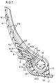
- FIGS 1 and 2 show an embodiment of a radial tire for aircraft in accordance with the invention.
- the tire 10 is a pressure vessel in which internal air pressure is maintained by the carcass 12.
- the carcass has a toroidal cross-section and is composed of a plurality of rubberized fiber (e.g. nylon, polyester or aramid) cords or steel cords.
- the tire 10 has a radial construction in which the axial direction of the carcass cords extends along the direction of tire width (at the crown).
- the surface of the carcass 12 is covered by a rubber layer 14.
- the rubber layer 14 has a function to protect the outside of the carcass 12 at the sidewall portion 16. Both edges of the carcass 12 are turned up around and retained at bead cores 18 which are formed to be circular with respect to the tire rotation axis.
- Each bead core 18 is covered by the rubber layer 14 and is a component of the bead portion 20.
- the bead portion 20 defines the internal dimension of the tire and secures engagement with a rim 21.
- the carcass 12 is composed of a main portion extending from the tread portion through the sidewalls 16 to the bead cores 18 of the bead portions 20 and turn-up portions turned up around the bead cores 18.
- a part 12A of the carcass 12 is turned up around the bead core 18 from the inside to the outside of the tire and terminates in the vicinity of the bead core 18, and another part 12B of the carcass is turned up around the bead core 18 from the inside to the outside of the tire and extended to the sidewall 16, and the remainder 12C of the carcass 12 is turned up around the bead core 18 from the outside to the inside of the tire and terminated adjacent the bead core 18 so as to cover the outer surface of the part 12A and the part 12B of the carcass.
- a 1st stiffener 40 extends radially outwardly at the radially outside of the bead core 18 and between the main portion of the carcass 12 and the turn-up portion of the carcass.
- the modulus MS1 of the 1st stiffener rubber at 100% elongation is 50 to 150 Kg/cm 2 .
- a 2nd stiffener 42 is provided at the bead portion and extends along the axially outer surface of the carcass 12.
- the modulus MS2 of the 2nd stiffener rubber at 100% elongation is 20 to 50 Kg/cm 2 .
- the modulus MS of the sidewall rubber 44 at 100% elongation is 10 to 40 Kg/cm 2 .
- the edge 44A of the sidewall rubber 44 at the bead portion side is covered by a rubber chafer 46.
- the rubber chafer 46 comprises the tire outer surface from the base 20A of the bead portion 20 to the sidewall portion 16 extending radially outwardly and comprises a portion to contact the rim flange 21A when the tire 10 is mounted on a normal rim 21 and inflated at normal inflation pressure and loaded with 200% weight of normal load.
- the modulus MC of the chafer rubber at 100% elongation is 25 to 60 Kg/cm 2 .
- the modulus MS of the sidewall rubber at 100% elongation, the modulus MS2 of the 2nd stiffener rubber at 100% elongation, the modulus MC of the rubber chafer rubber at 100% elongation and the modulus MS1 of the 1st stiffener rubber at 100% elongation have the relationship of MS ⁇ MS2 ⁇ MC ⁇ MS1.
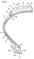
- a point C is located between a point A and a point B where, under the condition that the tire 10 is mounted on a normal rim 21 and inflated at normal inflation pressure, the point A is a tire surface point which departs from the rim flange 21A when the tire 10 is loaded with 100% weight of normal load, the point B is a tire surface point which departs from the rim flange 21A when the tire 10 is loaded with 200% weight of normal load, and the point C is the foot of a perpendicular H1 to the tire surface from the radially outermost point 40A of the 1st stiffener 40.
- CL aside the bead core 18 is preferably from 20% to 50% of BL, where CL is the rubber thickness between the tire surface and the outermost carcass ply and BL is the diameter of the bead core 18 in the direction of tire rotation.
- ML is located between the point A and the point B and ML is preferably from 35% to 65% of BL, where ML is the maximum value of CL in the zone between aside the bead core 18 and the maximum width of the sidewall 16.
- the rubber thickness GL of the rubber chafer 46 is preferably not less than 2.0 mm and is less than 50% of CL.
- the upper portion of the rubber layer 14 continues to the tread portion 22. Since the tread portion 22 actually contacts the road surface, it has sufficient thickness to endure wear and external damage.
- Folded belt layers 26, a non-folded belt layer 27 having circumferentially extending cords, folded belt layers 28 and non-folded belt layers 29, all of which are made of rubberized cord layer(s), are laminated and disposed between the carcass 12 and the tread portion 22, and the rigidity of the tire 10 is maintained by these belt layers 26, 27, 28 and 29.
- Several circumferentially extending grooves 30 are disposed in the tread portion 22, and several circumferentially extending ribs 32 are formed by these grooves 30. These grooves 30 have the function of water drainage, ornamental design and heat radiation from the tire 10.
- a protective layer 34 is disposed apart from and at the outside of the outermost belt 29.
- the protective layer 34 is a rubberized canvas made of for example aramid cords and has a function to protect the belt 29 so that cut damage on the surface of the tread portion 22 does not progress and reach the belt 29.
- the width of the protective layer 34 is preferably the same as or slightly narrower than the tread width.
- the strain of the radially outermost edge 40A of the 1st stiffener 40 at tire loading becomes large and consequently heat generation is increased.
- the point C of the foot of the perpendicular H1 to the tire surface from the radially outermost point 40A of the 1st stiffener 40 is located between the point A and the point B.
- CL aside the bead core 18 is preferably from 20% to 50% of BL, where CL is the rubber thickness between the tire surface and the outermost ply and BL is the diameter of the bead core 18 in the direction of tire rotation. If CL aside the bead core 18 is less than 20% of BL, since the contact pressure of the tire surface newly contacting with the rim flange 21A under load conditions is increased, the amount of rubber chafer chafing is increased. If CL aside the bead core is greater than 50% of BL, the effect of reducing the contact pressure is not improved further and the tire weight is increased due to increase of the rubber thickness.
- ML is located between the point A and the point B and ML is preferably from 35% to 65% of BL, where ML is the maximum value of CL in the zone between aside the bead core 18 and the maximum width of the sidewall portion 16.
- the rubber thickness CL between the tire surface and the outermost ply is arranged to be maximum between the point A and the point B so as to relax strain at the area.
- the rubber thickness GL of the rubber chafer 46 is preferably not less than 2.0 mm and is less than 50% of CL. If GL is less than 2.0 mm, since chafing strain of the rubber chafer 46 with the rim flange 21A, namely surface shearing strain (creasy deformation on the rubber surface) at the point of road contact-in and at the point of road contact-out during tire rotation becomes large, chafing of the rubber chafer easily occurs. If GL is greater than 50% of CL, the tire tends to blow out due to heat build-up inside the rubber chafer 46.
- B ⁇ 40A means the outermost edge 40A of the 1st stiffener is located higher than the point B.
- Tire Size 46 x 17R20.
- Carcass Construction The inner 4 plies are turned up around the bead core from the inside to the outside of the tire. The outer 2 plies are turned up around the bead core from the outside to the inside of the tire.
- Belt Construction Number of belt layers is 11, some of which are folded belt layers and the other are non-folded belt layers having circumferentially extending cords.
- Bead Construction Cable bead having 22.6 mm diameter.
- Test 1 take off drum test at 150% load of the normal load and at 225 mph under the condition of universal running mode Test 2 800 times repeated drum test of 8 minutes running per hour at 80% load of the normal load, namely 16700Kg and at 40 mph.
- Test 3 leave the tire alone outdoors after mounting on a rim and inflating at the normal inflation pressure Table 3 Test 1 Test 2 Test 3
- Example no damage no damage no ozone cracks at the sidewall rubber Comp.-1 damage A) damage (A) no ozone cracks at the sidewall rubber Comp.-2 damage (A) damage (A) no ozone cracks at the sidewall rubber Comp.-3 damage (B) damage (B) no ozone cracks at the sidewall rubber Comp.-4 no damage no damage ozone cracks occurred at the sidewall rubber Damage
- the tire in accordance with the invention has the above-mentioned structure, it has a superior effect of preventing damage at the bead portion.
Landscapes
- Engineering & Computer Science (AREA)
- Mechanical Engineering (AREA)
- Tires In General (AREA)
Claims (4)
- Radialer Luftreifen (10) für Flugzeuge, aufweisend:eine Karkasse (12), die zusammengesetzt ist aus einem Hauptbereich, der sich von einem Laufflächenbereich (22) über Seitenwandbereiche (16) bis zu Wulstkernen (18) von Wulstbereichen (20) erstreckt, und Umstülpbereichen, die um die Wulstkerne herumgeschlungen sind, wobei ein Teil (12A) der Karkasse von der Innenseite nach der Außenseite des Reifens herumgeschlungen ist und in der Nähe der Wulstkerne endet, ein weiterer Teil (12B) der Karkasse von der Innenseite nach der Außenseite des Reifens herumgeschlungen ist und sich bis zu den Seitenwandbereichen (16) erstreckt, und der restliche Teil (12C) der Karkasse von der Außenseite nach der Innenseite des Reifens um die Wulstkerne geschlungen ist und in der Nähe der Wulstkerne endet, so daß er die äußere Oberfläche der von der Innenseite nach der Außenseite herumgeschlungenen Karkasse bedeckt;einen Laufflächenbereich (22) zum Berühren der Straßenoberfläche, der in dem Kronenbereich der Karkasse (12) vorgesehen ist;Gürtel schichten (26, 27, 28, 29), die auf der radialen Außenseite der Karkasse (12), und auf der Innenseite der Lauffläche vorgesehen sind;erste Versteifungen (40), die sich von den Wulstkernen (18) radial nach außen, und zwischen dem Hauptbereich der Karkasse und den Umstülpbereichen der Karkasse erstrecken;zweite Versteifungen (42), die in den Wulstbereichen (20) vorgesehen sind, und sich längs der axial äußeren Oberfläche der Karkasse erstrecken;Seitenwandgummis (44), die die Seitenwandbereiche (16) aufweisen; undGummi-Wulstschutzstreifen (46), die die äußere Reifenoberfläche von den Seitenwandbereichen (16) bis zu der Wulstbasis (20A) aufweisen, und einen Bereich umfassen, um den Felgenflansch (21A) zu berühren, wenn der Reifen auf einer normalen Felge montiert wird, und auf den normalen Reifendruck aufgeblasen wird, und mit 200% der normalen Last belastet wird;
dadurch gekennzeichnet, daß:(a) der Modul MS des Seitenwandgummis bei 100% Dehnung, der Modul MS2 des Gummis der zweiten Versteifungen bei 100% Dehnung, der Modul MC des Gummis der Gummi-Wulstschutzstreifen bei 100% Dehnung, und der Modul MS1 des Gummis der ersten Versteifungen bei 100% Dehnung die Beziehung MS<MS2<MC<MS1 erfüllen; undb) ein Punkt C zwischen einem Punkt A und einem Punkt B gelegen ist, wobei unter der Bedingung, daß der Reifen auf einer normalen Felge (21) montiert ist und auf den normalen Reifendruck aufgeblasen ist, der Punkt A ein Reifenoberflächenpunkt ist, der sich von dem Felgenflansch (21A) abhebt, wenn der Reifen mit 100% der normalen Last belastet wird, der Punkt B ein Reifenoberflächenpunkt ist, der sich von dem Felgenflansch abhebt, wenn der Reifen mit 200% der normalen Last belastet wird, und der Punkt C der Fußpunkt einer Senkrechten (H1) auf der Reifenoberfläche von dem radial äußersten Punkt (40A) der ersten Versteifung (40) ist. - Luftreifen gemäß Anspruch 1, dadurch gekennzeichnet, daß CL auf der Seite des Wulstkerns (18) gleich 20% bis 50% von BL ist, wobei CL die Gummidicke zwischen der Reifenoberfläche und der äußersten Karkassenlage, und BL der Durchmesser des Wulstkerns ist.
- Luftreifen gemäß Anspruch 1 oder 2, dadurch gekennzeichnet, daß ML zwischen dem Punkt A und dem Punkt B gelegen ist, und ML gleich 35% bis 65% von BL ist, wobei ML der maximale Wert von CL in der Zone zwischen der Seite des Wulstkerns (18) und der maximalen Breite der Seitenwand ist, und wobei BL der Durchmesser des Wulstkerns ist, und CL die Gummidicke zwischen der Reifenoberfläche und der äußersten Karkassenlage ist.
- Luftreifen gemäß irgendeinem der Ansprüche 1 bis 3, dadurch gekennzeichnet, daß zwischen dem Punkt A und dem Punkt B die Gummidicke GL des Gummi-Wulstschutzstreifens (46) nicht kleiner als 2,0 mm, und kleiner als 50% von CL ist, wobei CL die Gummidicke zwischen der Reifenoberfläche und der äußersten Karkassenlage ist.
Applications Claiming Priority (2)
| Application Number | Priority Date | Filing Date | Title |
|---|---|---|---|
| JP322849/93 | 1993-12-21 | ||
| JP32284993A JP3437235B2 (ja) | 1993-12-21 | 1993-12-21 | 航空機用ラジアルタイヤ |
Publications (3)
| Publication Number | Publication Date |
|---|---|
| EP0659596A2 EP0659596A2 (de) | 1995-06-28 |
| EP0659596A3 EP0659596A3 (de) | 1995-10-04 |
| EP0659596B1 true EP0659596B1 (de) | 1997-09-10 |
Family
ID=18148288
Family Applications (1)
| Application Number | Title | Priority Date | Filing Date |
|---|---|---|---|
| EP19940307718 Expired - Lifetime EP0659596B1 (de) | 1993-12-21 | 1994-10-20 | Radialer Reifen für Flugzeuge |
Country Status (3)
| Country | Link |
|---|---|
| US (1) | US5476129A (de) |
| EP (1) | EP0659596B1 (de) |
| JP (1) | JP3437235B2 (de) |
Families Citing this family (24)
| Publication number | Priority date | Publication date | Assignee | Title |
|---|---|---|---|---|
| JP3329536B2 (ja) * | 1993-11-16 | 2002-09-30 | 株式会社ブリヂストン | 重荷重用空気入りラジアルタイヤ |
| EP0818331B1 (de) * | 1996-07-08 | 2002-09-25 | Bridgestone Corporation | Radiale LKW-Reifen |
| US6374883B1 (en) * | 2000-05-19 | 2002-04-23 | The Goodyear Tire & Rubber Company | Aircraft tire with two aquachannels |
| AU2002219034A1 (en) * | 2000-10-10 | 2002-04-22 | Michelin Recherche Et Technique S.A. | Tire bead with soft heel |
| FR2821794B1 (fr) * | 2001-03-09 | 2004-02-27 | Michelin Soc Tech | Armature de carcasse pour pneumatique d'avion |
| FR2823698B1 (fr) * | 2001-04-19 | 2004-05-07 | Michelin Soc Tech | Armatures de pneumatique pour avion |
| US6648041B2 (en) * | 2001-08-31 | 2003-11-18 | The Goodyear Tire & Rubber Company | Aircraft tire with improved bead structure |
| JP4878110B2 (ja) * | 2004-08-27 | 2012-02-15 | 株式会社ブリヂストン | 航空機用空気入りラジアルタイヤ |
| JP4953636B2 (ja) * | 2006-01-17 | 2012-06-13 | 株式会社ブリヂストン | 航空機用空気入りラジアルタイヤ及びその製造方法 |
| JP5201941B2 (ja) * | 2007-10-19 | 2013-06-05 | 株式会社ブリヂストン | 高荷重用空気入りラジアルタイヤ |
| JP5159575B2 (ja) * | 2008-11-18 | 2013-03-06 | 株式会社ブリヂストン | 航空機用ラジアルタイヤ |
| US8376011B2 (en) * | 2008-12-15 | 2013-02-19 | The Goodyear Tire & Rubber Company | Aircraft radial tire |
| US8539999B2 (en) * | 2008-12-16 | 2013-09-24 | The Goodyear Tire & Rubber Company | Tire with chafer |
| JP5398345B2 (ja) | 2009-05-18 | 2014-01-29 | 株式会社ブリヂストン | 重荷重用空気入りタイヤ |
| US8939185B2 (en) * | 2009-09-16 | 2015-01-27 | Bridgestone Corporation | Pneumatic radial tire |
| FR2961128B1 (fr) * | 2010-06-15 | 2012-06-15 | Michelin Soc Tech | Pneumatique ayant des bourrelets perfectionnes. |
| US9272577B2 (en) * | 2011-06-13 | 2016-03-01 | The Goodyear Tire & Rubber Company | Aircraft radial tire |
| US20130056126A1 (en) * | 2011-09-06 | 2013-03-07 | Kiyoshi Ueyoko | Aircraft tire |
| US9096100B2 (en) | 2012-11-12 | 2015-08-04 | The Goodyear Tire & Rubber Company | Tire with chafer and sidewall |
| FR2998513B1 (fr) * | 2012-11-29 | 2016-05-06 | Michelin & Cie | Bourrelet de pneumatique pour avion |
| EP2878458B1 (de) | 2013-11-27 | 2018-12-26 | The Goodyear Tire & Rubber Company | Pneumatischer Reifen |
| JP6393194B2 (ja) * | 2015-01-13 | 2018-09-19 | 住友ゴム工業株式会社 | タイヤ |
| JP6772766B2 (ja) * | 2016-11-09 | 2020-10-21 | 住友ゴム工業株式会社 | 空気入りタイヤ |
| JP7672287B2 (ja) * | 2021-06-15 | 2025-05-07 | 株式会社ブリヂストン | 航空機用ラジアルタイヤ |
Family Cites Families (6)
| Publication number | Priority date | Publication date | Assignee | Title |
|---|---|---|---|---|
| FR1558385A (de) * | 1967-11-27 | 1969-02-28 | ||
| FR2632252B1 (fr) * | 1988-04-28 | 1994-09-16 | Bridgestone Corp | Pneumatique radial renforce a haute pression interne |
| US5085260A (en) * | 1988-12-28 | 1992-02-04 | Sumitomo Rubber Industries, Ltd. | Heavy duty radial tire with a carcass turnup portion having specific dimensions |
| JP2793672B2 (ja) * | 1989-12-28 | 1998-09-03 | 住友ゴム工業株式会社 | 高速重荷重用タイヤ |
| JP2986896B2 (ja) * | 1990-11-01 | 1999-12-06 | 株式会社ブリヂストン | 航空機用ラジアルタイヤ |
| JPH0592709A (ja) * | 1990-12-10 | 1993-04-16 | Sumitomo Rubber Ind Ltd | 高速重荷重用タイヤ |
-
1993
- 1993-12-21 JP JP32284993A patent/JP3437235B2/ja not_active Expired - Fee Related
-
1994
- 1994-10-20 EP EP19940307718 patent/EP0659596B1/de not_active Expired - Lifetime
- 1994-11-22 US US08/346,271 patent/US5476129A/en not_active Expired - Lifetime
Also Published As
| Publication number | Publication date |
|---|---|
| US5476129A (en) | 1995-12-19 |
| EP0659596A3 (de) | 1995-10-04 |
| EP0659596A2 (de) | 1995-06-28 |
| JP3437235B2 (ja) | 2003-08-18 |
| JPH07172118A (ja) | 1995-07-11 |
Similar Documents
| Publication | Publication Date | Title |
|---|---|---|
| EP0659596B1 (de) | Radialer Reifen für Flugzeuge | |
| EP0638445B1 (de) | Radialluftreifen | |
| EP0371755B1 (de) | Sicherheits-Luftreifen | |
| EP0810106A2 (de) | Radialer LKW-Reifen | |
| US5637164A (en) | Aircraft tire with reinforcement insert | |
| EP0314445A2 (de) | Sicherheitsluftreifen | |
| US6478064B1 (en) | Heavy duty radial tire with chafer height greater than bead apex height | |
| EP0681928B1 (de) | Verbesserter Reifen für Flugzeug | |
| RU2595095C2 (ru) | Шина для сельскохозяйственных и лесозаготовительных машин (варианты) | |
| EP0736400B1 (de) | Schwerlastradialluftreifen | |
| EP1201464B1 (de) | Radiale Luftreifen | |
| US6712108B1 (en) | Discontinuous ply for runflat tire construction | |
| EP1527907A2 (de) | Selbstragender Luftreifen | |
| US6719029B2 (en) | Tire wall gauges to optimize runflat tire ride comfort | |
| EP0844109B1 (de) | LKW-Radialreifen | |
| EP0545681B1 (de) | Sicherheitsluftreifen | |
| EP1145874B1 (de) | Flipperreifenstruktur für Notlaufreifen | |
| US6763866B1 (en) | Reinforced wedge-insert construction for extended mobility tires | |
| EP1366930B1 (de) | Radiale LKW-Reifen | |
| JPH07144516A (ja) | 高速重荷重用タイヤ | |
| EP1205316B1 (de) | Luftreifen mit gekreuzter Karkasse für Flugzeuge | |
| EP0700797A2 (de) | Radialer Luftreifen | |
| EP0698513B1 (de) | Radialer Luftreifen | |
| EP0667250B1 (de) | Luftreifen und Verfahren zu seiner Herstellung | |
| EP1181161B1 (de) | Konstruktion basierend auf verstärkten keil-inserts für reifen mit notlauf-eigenschaften |
Legal Events
| Date | Code | Title | Description |
|---|---|---|---|
| PUAI | Public reference made under article 153(3) epc to a published international application that has entered the european phase |
Free format text: ORIGINAL CODE: 0009012 |
|
| AK | Designated contracting states |
Kind code of ref document: A2 Designated state(s): FR GB LU |
|
| PUAL | Search report despatched |
Free format text: ORIGINAL CODE: 0009013 |
|
| AK | Designated contracting states |
Kind code of ref document: A3 Designated state(s): FR GB LU |
|
| 17P | Request for examination filed |
Effective date: 19951218 |
|
| GRAG | Despatch of communication of intention to grant |
Free format text: ORIGINAL CODE: EPIDOS AGRA |
|
| 17Q | First examination report despatched |
Effective date: 19970109 |
|
| GRAH | Despatch of communication of intention to grant a patent |
Free format text: ORIGINAL CODE: EPIDOS IGRA |
|
| GRAH | Despatch of communication of intention to grant a patent |
Free format text: ORIGINAL CODE: EPIDOS IGRA |
|
| GRAA | (expected) grant |
Free format text: ORIGINAL CODE: 0009210 |
|
| AK | Designated contracting states |
Kind code of ref document: B1 Designated state(s): FR GB LU |
|
| ET | Fr: translation filed | ||
| PLBE | No opposition filed within time limit |
Free format text: ORIGINAL CODE: 0009261 |
|
| STAA | Information on the status of an ep patent application or granted ep patent |
Free format text: STATUS: NO OPPOSITION FILED WITHIN TIME LIMIT |
|
| 26N | No opposition filed | ||
| PGFP | Annual fee paid to national office [announced via postgrant information from national office to epo] |
Ref country code: LU Payment date: 19981020 Year of fee payment: 5 |
|
| PG25 | Lapsed in a contracting state [announced via postgrant information from national office to epo] |
Ref country code: LU Free format text: LAPSE BECAUSE OF NON-PAYMENT OF DUE FEES Effective date: 19991020 |
|
| REG | Reference to a national code |
Ref country code: GB Ref legal event code: IF02 |
|
| PGFP | Annual fee paid to national office [announced via postgrant information from national office to epo] |
Ref country code: FR Payment date: 20131022 Year of fee payment: 20 Ref country code: GB Payment date: 20131021 Year of fee payment: 20 |
|
| REG | Reference to a national code |
Ref country code: GB Ref legal event code: PE20 Expiry date: 20141019 |
|
| PG25 | Lapsed in a contracting state [announced via postgrant information from national office to epo] |
Ref country code: GB Free format text: LAPSE BECAUSE OF EXPIRATION OF PROTECTION Effective date: 20141019 |