EP0658450A2 - Bandage pneumatique - Google Patents
Bandage pneumatique Download PDFInfo
- Publication number
- EP0658450A2 EP0658450A2 EP94309359A EP94309359A EP0658450A2 EP 0658450 A2 EP0658450 A2 EP 0658450A2 EP 94309359 A EP94309359 A EP 94309359A EP 94309359 A EP94309359 A EP 94309359A EP 0658450 A2 EP0658450 A2 EP 0658450A2
- Authority
- EP
- European Patent Office
- Prior art keywords
- tyre
- tread
- breaker
- point
- tyre according
- Prior art date
- Legal status (The legal status is an assumption and is not a legal conclusion. Google has not performed a legal analysis and makes no representation as to the accuracy of the status listed.)
- Granted
Links
Images

Classifications
-
- B—PERFORMING OPERATIONS; TRANSPORTING
- B60—VEHICLES IN GENERAL
- B60C—VEHICLE TYRES; TYRE INFLATION; TYRE CHANGING; CONNECTING VALVES TO INFLATABLE ELASTIC BODIES IN GENERAL; DEVICES OR ARRANGEMENTS RELATED TO TYRES
- B60C9/00—Reinforcements or ply arrangement of pneumatic tyres
- B60C9/18—Structure or arrangement of belts or breakers, crown-reinforcing or cushioning layers
-
- B—PERFORMING OPERATIONS; TRANSPORTING
- B60—VEHICLES IN GENERAL
- B60C—VEHICLE TYRES; TYRE INFLATION; TYRE CHANGING; CONNECTING VALVES TO INFLATABLE ELASTIC BODIES IN GENERAL; DEVICES OR ARRANGEMENTS RELATED TO TYRES
- B60C11/00—Tyre tread bands; Tread patterns; Anti-skid inserts
- B60C11/0083—Tyre tread bands; Tread patterns; Anti-skid inserts characterised by the curvature of the tyre tread
-
- B—PERFORMING OPERATIONS; TRANSPORTING
- B60—VEHICLES IN GENERAL
- B60C—VEHICLE TYRES; TYRE INFLATION; TYRE CHANGING; CONNECTING VALVES TO INFLATABLE ELASTIC BODIES IN GENERAL; DEVICES OR ARRANGEMENTS RELATED TO TYRES
- B60C11/00—Tyre tread bands; Tread patterns; Anti-skid inserts
-
- B—PERFORMING OPERATIONS; TRANSPORTING
- B60—VEHICLES IN GENERAL
- B60C—VEHICLE TYRES; TYRE INFLATION; TYRE CHANGING; CONNECTING VALVES TO INFLATABLE ELASTIC BODIES IN GENERAL; DEVICES OR ARRANGEMENTS RELATED TO TYRES
- B60C3/00—Tyres characterised by the transverse section
- B60C3/04—Tyres characterised by the transverse section characterised by the relative dimensions of the section, e.g. low profile
-
- B—PERFORMING OPERATIONS; TRANSPORTING
- B60—VEHICLES IN GENERAL
- B60C—VEHICLE TYRES; TYRE INFLATION; TYRE CHANGING; CONNECTING VALVES TO INFLATABLE ELASTIC BODIES IN GENERAL; DEVICES OR ARRANGEMENTS RELATED TO TYRES
- B60C9/00—Reinforcements or ply arrangement of pneumatic tyres
- B60C9/18—Structure or arrangement of belts or breakers, crown-reinforcing or cushioning layers
- B60C9/20—Structure or arrangement of belts or breakers, crown-reinforcing or cushioning layers built-up from rubberised plies each having all cords arranged substantially parallel
-
- Y—GENERAL TAGGING OF NEW TECHNOLOGICAL DEVELOPMENTS; GENERAL TAGGING OF CROSS-SECTIONAL TECHNOLOGIES SPANNING OVER SEVERAL SECTIONS OF THE IPC; TECHNICAL SUBJECTS COVERED BY FORMER USPC CROSS-REFERENCE ART COLLECTIONS [XRACs] AND DIGESTS
- Y10—TECHNICAL SUBJECTS COVERED BY FORMER USPC
- Y10T—TECHNICAL SUBJECTS COVERED BY FORMER US CLASSIFICATION
- Y10T152/00—Resilient tires and wheels
- Y10T152/10—Tires, resilient
- Y10T152/10495—Pneumatic tire or inner tube
- Y10T152/10765—Characterized by belt or breaker structure
Definitions
- the present invention relates to a pneumatic tyre for vehicles having a radial tyre and a tread reinforcing breaker and is particularly applicable to car tyres but not limited thereto.
- a pneumatic radial tyre for a vehicle comprises a carcass ply extending between two bead regions and passing through a tread region which extends between two tread contact edges, a tread region reinforcing breaker radially outwards of the carcass in the tread region and a ground contacting tread surface curved in the axial direction characterised in the curvature of the outer tread surface when the tyre is mounted in a wheel rim and normally inflated has a continuously decreasing radius from a point P which is at a distance SP in the axial direction from the tyre circumferential centreline equal to 20% of the distance from the tread centre to the adjacent tread contact edge.
- tread contact edge is meant the edge point axially of the tyre at which the tread surface is contacted by the road surface in use of the tyre.
- the tread contact surface may have a radius of curvature which decreases at a constant rate.
- the polar co-ordinates R, ⁇ have an origin on the circumferential centreline C at a distance of (70.63044 x (SW/194))mm below the point of intersection of the circumferential centreline C with the tread surface.
- the invention includes a tread surface curve lying within two curves generated with the above ⁇ 4% in relation to the radius. More preferably the curve is within ⁇ 2% of the radius.
- a pneumatic tyre for a vehicle comprising a carcass ply extending between the bead regions and passing through a tread region which extends between two tread contact edges, a tread region reinforcing breaker radially outwards of the carcass in the tread region and a ground contacting tread surface curved in the axial direction characterised in that the outer surface of the breaker has a curved shape in the tyre axial direction and has a decreasing radius from a point B to the edge of the breaker wherein point B is spaced apart from the tyre circumferential centreline by a distance SP equal to 20% of the distance from the tread centre to the tread contact edge.
- the particular profile may be defined by an equation relating the polar co-ordinates and in broader aspects ranges of ⁇ 4% and more preferably ⁇ 2% of the radius.
- the invention Whilst the invention relates primarily to a tyre having a tread region and/or a breaker construction having the declared curvature the said curvature in a preferred arrangement continues along the sidewall regions of the tyre substantially from bead region to bead region.
- the thickness of the tread rubber decreases from a point P on the tread surface to the tread edge wherein the point P is set at a distance SP from the circumferential centreline C being equal to 20% of the distance between the circumferential centreline and the tread edge.
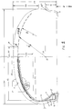
- the tyre of Figure 1 comprises a 195.45R16 car tyre, for a 61 ⁇ 2'' x 16'' wheel rim, and has a tread region 1 reinforced by a breaker assembly 2 and a pair of sidewalls 3.
- a single ply of radially extending cords provides a carcass reinforcement 4 which extends from bead to bead of the tyre and is wrapped at each edge from the inside to the outside in the axial direction around a bead core 5.
- the edge region 6 of the ply 4 is turned up radially outwards to give a ply turnup.
- a rubber apex 7 is positioned on top of the bead core 5 in a conventional manner and a chafer 8 is wrapped around the bead 5 inwards of the ply 4 to provide a cushion for the ply around the bead core 5 and apex 7.
- a clinch strip 9 is also positioned around the bead. The components in the bead provide a substantially conventional bead region.
- the tyre carcass has a substantially curbed cross-sectional shape to match the breaker package which in turn matches a substantially curved tyre tread surface of the tread region 1.
- the curvature of the tread region is one of the important features of this invention and reference to the right-hand side of the Figure shows that the tread region has a gradually decreasing radius of curvature moving outwards from the centreline of the tyre. More specifically the tread region has a radius of curvature which continually decreases to either side of the centreline outwards of a point P on the tread surface which is a distance equal to 20% of the distance from the centreline C to the tread contact edge point.
- the embodiment has a tread surface shape with the progressively reducing radius of curvature RC defined by an equation which gives the locus of a point PT using polar coordinates R and ⁇ having an origin O on the centreline of the tyre cross-section C substantially below the centre of the tyre tread surface and at a similar height to the top of the flange for the wheel rim 11 on which the tyre is mounted. It should be understood however that some variation on the curve is possible.
- the shape for a practicable tyre may be within ⁇ 4% of the radius according to the detailed formala which follows and relates specifically to this embodiment. More preferably the shape needs to be within ⁇ 2%.
- the flange height G provides a contact point BP where the tyre sidewall touches the flange.
- the flange height G for the tyre and wheel of the assembly of a body 1 is 17.3mm.
- the centre O was set at a height from the bead seat diameter D of 20.4mm. The height of the point O is not critical but needs to be set so that the locus can be calculated.
- the tyre tread surface 10 having the shape defined.
- the shape may continue to the edge of the tread rubber. However, in the embodiment the shape continues around the sidewall of the tyre substantially to the point BP where the tyre sidewall contacts the flange of its wheel rim.
- the sidewalls 2 have the outer profile shape defined by the same equation as the tread.
- the tread width SW is the section width of the tyre because the tread region extends in this way. This is not an essential feature of the invention for the tread width to equal the section width but is preferred.
- FIG. 2 utilises the same numerals to show a construction in which the curvature of the top breaker ply 2B is defined by a similar equation.
- the curvature of the outer surface of the widest breaker ply is defined by the locus of a point PT with polar co-ordinates R B , ⁇ having an origin on the circumferential centreline C at a distance below the point of intersection of the circumferential centreline C with the tread surface
- R B (89.02495 + 58.35249 x ⁇ - 194.2836 x ⁇ 2 + 168.7756 x ⁇ 3 - 62.10578 x ⁇ 4 + 8.747225 x ⁇ 5)
- x (SW/194) as ⁇ decreases in the range from ⁇ /2 radians to zero and wherein SW is the value in millimetres of the maximum section width of the tyre.
- the invention also includes a shape generated by polar co-ordinates where the radius is within ⁇ 4% or more preferably ⁇ 2% of the above curve radius.
- the tread surface has the profile set out in its general shape. This does not exclude the provision of pattern grooves in the surface from normal sipes which are very narrow cuts to quite wide water-retaining grooves in either or both of the circumferential or axial directions.
- the tread pattern may also include a very wide centre groove of the type currently fashionable.
- the tread region 1 has a rubber compound thickness measured perpendicularly to the surface of the tread which reduces continuously from the centre (C) of the tread to each shoulder.
- This type of tread thickness is unconventional and typically radial tyres have an increasing or constant tread thickness towards the shoulder even when the shoulders themselves are rounded to give even wear appearance on the tyre in service.
- the tread reinforcing breaker of the present tyre comprises three plies, 2A, 2B and 2C. Beginning with the radially innermost ply 2A the construction comprises an inner breaker ply 2A having a width B1 of 180mm measured in the axial direction of the tyre.
- the outer breaker ply in common with the others lies substantially parallel to the tread surface profile 10 which means that the ply itself is cut substantially wider than 180mm.
- the next ply 2B has a width B2 which in the finished tyre is 180mm measured in the axial direction and is loaded with cords at an opposite acute angle to the first ply.
- a third breaker ply 2C is positioned centrally of the tyre and has a finished axial width of 150mm so that its edges do not reach to the edges of the first and second plies 2A and 2B.
- the three breaker plies 2A, 2B and 2C all comprise aramid cords material (Kevlar Registered Trade Mark) each cut at 25° prior to manufacture.
- the cord plies are topped with topping compound.
- an important feature of the invention is that the profile of the breaker 2 is the same as that of the tread surface 10 so that the package of tread surface, tread thickness and breaker each follow the declared shape.
- the radial reinforcement carcass 4 comprises nylon reinforcing cords laid substantially at 90° and lying adjacent to the inner breaker ply 2A.
- the resultant tyre has a reinforced tread region of substantial curvature when considered in transverse cross-section.
- the tread curvature is such that the ratio TH/SW of the radial distance between the tread edge and the tread centre to the maximum tyre section width has a value of 0.27. This is very different to normal car and truck tyres where the intention of the designer has hitherto been to make the breaker as flat a possible to maintain a flat contact between the tread region and the road.
- the combination of tread and breaker shape together with the tread thickness being substantially constant or in fact diminished across the full width of the tyre to the shoulders provides a tyre in which when the vehicle is running straight the contact patch is substantially less that the width of the tyre.
- the tyre has a contact patch which can more to either side of the centreline and/or increase in transverse width with lateral/radial changes of load on the wheel concerned.
- the invention is not limited to such materials. Any of the normal high tensile materials can be used for the breaker package as can two, three, four or more plies.
- the carcass may also comprise other materials including rayon and may be of single or dual ply construction.
- the tyre described is a 45 aspect ratio tyre and therefore comprises short sidewalls.
- the invention however is not limited thereto as it resides primarily in the shape of the tread surface and the breaker package thereunder.
- bead construction may be varied including making the apex strip of different sizes and hardnesses and any of the known bead retention systems may be utilised.
Applications Claiming Priority (4)
| Application Number | Priority Date | Filing Date | Title |
|---|---|---|---|
| GB9325716 | 1993-12-16 | ||
| GB939325715A GB9325715D0 (en) | 1993-12-16 | 1993-12-16 | Pneumatic tyre |
| GB9325715 | 1993-12-16 | ||
| GB939325716A GB9325716D0 (en) | 1993-12-16 | 1993-12-16 | Pneumatic tyre |
Publications (3)
| Publication Number | Publication Date |
|---|---|
| EP0658450A2 true EP0658450A2 (fr) | 1995-06-21 |
| EP0658450A3 EP0658450A3 (fr) | 1995-08-30 |
| EP0658450B1 EP0658450B1 (fr) | 1997-06-04 |
Family
ID=26304037
Family Applications (1)
| Application Number | Title | Priority Date | Filing Date |
|---|---|---|---|
| EP94309359A Expired - Lifetime EP0658450B1 (fr) | 1993-12-16 | 1994-12-14 | Bandage pneumatique |
Country Status (7)
| Country | Link |
|---|---|
| US (2) | US5630892A (fr) |
| EP (1) | EP0658450B1 (fr) |
| JP (1) | JP3358900B2 (fr) |
| KR (1) | KR0169339B1 (fr) |
| AU (1) | AU679797B2 (fr) |
| CA (1) | CA2137999C (fr) |
| DE (1) | DE69403616T2 (fr) |
Cited By (8)
| Publication number | Priority date | Publication date | Assignee | Title |
|---|---|---|---|---|
| EP0778162A1 (fr) | 1995-12-05 | 1997-06-11 | Sumitomo Rubber Industries Limited | Pneumatique |
| EP0872361A2 (fr) * | 1997-04-16 | 1998-10-21 | Sumitomo Rubber Industries Ltd. | Bandage pneumatique de véhicule |
| EP0985557A2 (fr) * | 1998-08-04 | 2000-03-15 | Sumitomo Rubber Industries Ltd. | Bandage pneumatique pour roulage à plat |
| WO2001015917A1 (fr) * | 1999-08-31 | 2001-03-08 | Dunlop Gmbh | Pneu pour vehicule |
| US6318429B1 (en) | 1997-07-12 | 2001-11-20 | Sumitomo Rubber Industries Limited | Tire with breaker ply extending between bead regions |
| US6941991B2 (en) * | 2000-02-01 | 2005-09-13 | The Goodyear Tire & Rubber Company | Radial tire with improved ply line |
| EP2112004A1 (fr) * | 2007-02-14 | 2009-10-28 | Bridgestone Corporation | Pneu |
| US20200062038A1 (en) * | 2017-05-10 | 2020-02-27 | Bridgestone Corporation | Pneumatic tire |
Families Citing this family (13)
| Publication number | Priority date | Publication date | Assignee | Title |
|---|---|---|---|---|
| JPH07242105A (ja) * | 1994-03-04 | 1995-09-19 | Bridgestone Corp | 重荷重用空気入りタイヤ |
| EP0812708B1 (fr) * | 1996-06-11 | 2001-11-28 | Bridgestone Corporation | Bandages pneumatiques radiaux |
| JP3198070B2 (ja) * | 1997-04-16 | 2001-08-13 | 住友ゴム工業株式会社 | 空気入りタイヤ |
| AU5097598A (en) * | 1997-10-30 | 1999-05-24 | Goodyear Tire And Rubber Company, The | A radial pneumatic light truck or automobile tire |
| US6367526B1 (en) | 1997-10-30 | 2002-04-09 | The Goodyear Tire & Rubber Company | Radial pneumatic light truck or automobile tire |
| US6408909B1 (en) | 1998-01-15 | 2002-06-25 | The Goodyear Tire & Rubber Company | Radial runflat passenger tire with improved tread contour with decoupling grooves |
| JP4286363B2 (ja) * | 1999-02-10 | 2009-06-24 | 株式会社ブリヂストン | 方向性傾斜溝を有する空気入りタイヤ |
| JP4812344B2 (ja) * | 2005-05-31 | 2011-11-09 | 株式会社ブリヂストン | 空気入りタイヤ |
| JP4818266B2 (ja) * | 2005-05-31 | 2011-11-16 | 株式会社ブリヂストン | 空気入りタイヤ |
| JP4785425B2 (ja) * | 2005-06-02 | 2011-10-05 | 株式会社ブリヂストン | 空気入りタイヤ |
| US20080216930A1 (en) * | 2007-03-05 | 2008-09-11 | Christopher John Valentine | Tyre with rubber tread which contains internal circumferential rubber stabilizer bars |
| JP4249791B2 (ja) * | 2007-08-10 | 2009-04-08 | 住友ゴム工業株式会社 | タイヤ |
| JP5559235B2 (ja) * | 2012-04-12 | 2014-07-23 | 住友ゴム工業株式会社 | 空気入りタイヤ |
Citations (6)
| Publication number | Priority date | Publication date | Assignee | Title |
|---|---|---|---|---|
| FR2417403A1 (fr) * | 1978-02-21 | 1979-09-14 | Michelin & Cie | Pneumatique en materiau elastique non arme |
| FR2417404A1 (fr) * | 1978-02-21 | 1979-09-14 | Michelin & Cie | Pneumatique en materiau elastique sans armature |
| FR2417405A1 (fr) * | 1978-02-21 | 1979-09-14 | Michelin & Cie | Perfectionnement aux pneumatiques en materiau elastique non arme |
| DE4002824A1 (de) * | 1989-03-15 | 1990-09-20 | Bridgestone Corp | Luftguertelreifen |
| EP0477542A2 (fr) * | 1990-09-04 | 1992-04-01 | The Goodyear Tire & Rubber Company | Bandage pneumatique |
| US5247979A (en) * | 1990-07-09 | 1993-09-28 | Sumitomo Rubber Industries Limited | Radial tire with specified tread profile |
Family Cites Families (7)
| Publication number | Priority date | Publication date | Assignee | Title |
|---|---|---|---|---|
| FR2503053A1 (fr) * | 1981-04-03 | 1982-10-08 | Michelin & Cie | Pneumatique a carcasse radiale pour lourdes charges |
| JPH01141104A (ja) * | 1987-11-27 | 1989-06-02 | Sumitomo Rubber Ind Ltd | 重荷重用空気入りラジアルタイヤ |
| CA2007058A1 (fr) * | 1989-06-09 | 1990-12-09 | Adel Farhan Halasa | Pneumatiques |
| JPH0524414A (ja) * | 1991-07-23 | 1993-02-02 | Sumitomo Rubber Ind Ltd | ラジアルタイヤ |
| JP2643058B2 (ja) * | 1991-08-26 | 1997-08-20 | 住友ゴム工業株式会社 | 空気入りラジアルタイヤ |
| US5360047A (en) * | 1991-11-08 | 1994-11-01 | Sumitomo Rubber Industries, Ltd. | Heavy duty radial tire with specified belt radius |
| JP2574971B2 (ja) * | 1992-06-22 | 1997-01-22 | 住友ゴム工業株式会社 | 空気入りタイヤ |
-
1994
- 1994-12-09 JP JP33180094A patent/JP3358900B2/ja not_active Expired - Fee Related
- 1994-12-13 AU AU80379/94A patent/AU679797B2/en not_active Ceased
- 1994-12-13 CA CA002137999A patent/CA2137999C/fr not_active Expired - Fee Related
- 1994-12-14 EP EP94309359A patent/EP0658450B1/fr not_active Expired - Lifetime
- 1994-12-14 DE DE69403616T patent/DE69403616T2/de not_active Expired - Lifetime
- 1994-12-15 US US08/356,552 patent/US5630892A/en not_active Expired - Lifetime
- 1994-12-16 KR KR1019940034767A patent/KR0169339B1/ko not_active IP Right Cessation
-
1996
- 1996-04-23 US US08/636,644 patent/US5630893A/en not_active Expired - Lifetime
Patent Citations (6)
| Publication number | Priority date | Publication date | Assignee | Title |
|---|---|---|---|---|
| FR2417403A1 (fr) * | 1978-02-21 | 1979-09-14 | Michelin & Cie | Pneumatique en materiau elastique non arme |
| FR2417404A1 (fr) * | 1978-02-21 | 1979-09-14 | Michelin & Cie | Pneumatique en materiau elastique sans armature |
| FR2417405A1 (fr) * | 1978-02-21 | 1979-09-14 | Michelin & Cie | Perfectionnement aux pneumatiques en materiau elastique non arme |
| DE4002824A1 (de) * | 1989-03-15 | 1990-09-20 | Bridgestone Corp | Luftguertelreifen |
| US5247979A (en) * | 1990-07-09 | 1993-09-28 | Sumitomo Rubber Industries Limited | Radial tire with specified tread profile |
| EP0477542A2 (fr) * | 1990-09-04 | 1992-04-01 | The Goodyear Tire & Rubber Company | Bandage pneumatique |
Cited By (14)
| Publication number | Priority date | Publication date | Assignee | Title |
|---|---|---|---|---|
| EP0778162A1 (fr) | 1995-12-05 | 1997-06-11 | Sumitomo Rubber Industries Limited | Pneumatique |
| US6575214B1 (en) * | 1997-04-16 | 2003-06-10 | Sumitomo Rubber Industries, Ltd. | Vehicle tire including tread portion defined by cycloid curve or epicycloid curve |
| EP0872361A2 (fr) * | 1997-04-16 | 1998-10-21 | Sumitomo Rubber Industries Ltd. | Bandage pneumatique de véhicule |
| EP0872361A3 (fr) * | 1997-04-16 | 2000-11-22 | Sumitomo Rubber Industries Ltd. | Bandage pneumatique de véhicule |
| US6821369B2 (en) | 1997-07-12 | 2004-11-23 | Sumitomo Rubber Industries, Ltd. | Single-stage method of fabricating radial tire with breaker ply extending between bead regions |
| US6318429B1 (en) | 1997-07-12 | 2001-11-20 | Sumitomo Rubber Industries Limited | Tire with breaker ply extending between bead regions |
| EP0985557A3 (fr) * | 1998-08-04 | 2001-12-19 | Sumitomo Rubber Industries Ltd. | Bandage pneumatique pour roulage à plat |
| EP0985557A2 (fr) * | 1998-08-04 | 2000-03-15 | Sumitomo Rubber Industries Ltd. | Bandage pneumatique pour roulage à plat |
| WO2001015917A1 (fr) * | 1999-08-31 | 2001-03-08 | Dunlop Gmbh | Pneu pour vehicule |
| US6672351B1 (en) | 1999-08-31 | 2004-01-06 | Dunlop Gmbh | Vehicle tire with continously reducing vertical spacing of tread surface with respect to breaker |
| US6941991B2 (en) * | 2000-02-01 | 2005-09-13 | The Goodyear Tire & Rubber Company | Radial tire with improved ply line |
| EP2112004A1 (fr) * | 2007-02-14 | 2009-10-28 | Bridgestone Corporation | Pneu |
| EP2112004A4 (fr) * | 2007-02-14 | 2011-05-04 | Bridgestone Corp | Pneu |
| US20200062038A1 (en) * | 2017-05-10 | 2020-02-27 | Bridgestone Corporation | Pneumatic tire |
Also Published As
| Publication number | Publication date |
|---|---|
| CA2137999A1 (fr) | 1995-06-17 |
| AU679797B2 (en) | 1997-07-10 |
| DE69403616D1 (de) | 1997-07-10 |
| DE69403616T2 (de) | 1997-09-18 |
| KR0169339B1 (ko) | 1999-01-15 |
| US5630892A (en) | 1997-05-20 |
| KR950017252A (ko) | 1995-07-20 |
| EP0658450A3 (fr) | 1995-08-30 |
| JP3358900B2 (ja) | 2002-12-24 |
| CA2137999C (fr) | 2004-11-16 |
| JPH0825906A (ja) | 1996-01-30 |
| AU8037994A (en) | 1995-06-22 |
| EP0658450B1 (fr) | 1997-06-04 |
| US5630893A (en) | 1997-05-20 |
Similar Documents
| Publication | Publication Date | Title |
|---|---|---|
| EP0658450B1 (fr) | Bandage pneumatique | |
| EP0424155B1 (fr) | Bandage pneumatique radial | |
| US7900672B2 (en) | Pneumatic tire with annular reinforcing strip layer | |
| US5200006A (en) | Pneumatic tire with uniform ground pressure at the tread face | |
| EP3424751A1 (fr) | Pneumatique | |
| CA2159236A1 (fr) | Pneumatique et bande de roulement de pneumatique pour camion a essieu directeur | |
| US20060118220A1 (en) | Pneumatic tire with elliptical shoulder | |
| JPH10181309A (ja) | 空気入りラジアルタイヤ | |
| US6371179B1 (en) | Pneumatic tire including shoulder blocks | |
| EP1676723A1 (fr) | Pneumatique avec rainures transversales à l'épaule | |
| EP1207056B1 (fr) | Bandage pneumatique avec une forme d'empreinte au sol s'adaptant au poids à supporter | |
| EP1054782B1 (fr) | Pneu radial a vehicule de tourisme comportant une bande de roulement qui possede un meilleur profil et qui comprend des gorges de decouplage | |
| US5529102A (en) | Motorcycle radial tire with supplementary breaker ply | |
| EP0596737B1 (fr) | Bandage pneumatique radial | |
| US6367526B1 (en) | Radial pneumatic light truck or automobile tire | |
| US6408909B1 (en) | Radial runflat passenger tire with improved tread contour with decoupling grooves | |
| EP0748705B1 (fr) | Pneumatique | |
| JPH11348509A (ja) | 重荷重用空気入りラジアルタイヤ | |
| AU676587B2 (en) | An improved radial ply tire | |
| EP3599112B1 (fr) | Pneumatique sans crampons | |
| EP0835766B1 (fr) | Bandage pneumatique radial pour moto | |
| WO1999022952A1 (fr) | Pneumatique a carcasse radiale pour vehicule utilitaire leger ou automobile | |
| EP1072443A2 (fr) | Bandage pneumatique pour moto | |
| EP1110758A2 (fr) | Bandage pneumatique à bourrelet de diamètre élevé |
Legal Events
| Date | Code | Title | Description |
|---|---|---|---|
| PUAI | Public reference made under article 153(3) epc to a published international application that has entered the european phase |
Free format text: ORIGINAL CODE: 0009012 |
|
| AK | Designated contracting states |
Kind code of ref document: A2 Designated state(s): DE FR GB IT |
|
| PUAL | Search report despatched |
Free format text: ORIGINAL CODE: 0009013 |
|
| AK | Designated contracting states |
Kind code of ref document: A3 Designated state(s): DE FR GB IT |
|
| 17P | Request for examination filed |
Effective date: 19951017 |
|
| GRAG | Despatch of communication of intention to grant |
Free format text: ORIGINAL CODE: EPIDOS AGRA |
|
| 17Q | First examination report despatched |
Effective date: 19960905 |
|
| GRAH | Despatch of communication of intention to grant a patent |
Free format text: ORIGINAL CODE: EPIDOS IGRA |
|
| GRAH | Despatch of communication of intention to grant a patent |
Free format text: ORIGINAL CODE: EPIDOS IGRA |
|
| GRAA | (expected) grant |
Free format text: ORIGINAL CODE: 0009210 |
|
| AK | Designated contracting states |
Kind code of ref document: B1 Designated state(s): DE FR GB IT |
|
| REF | Corresponds to: |
Ref document number: 69403616 Country of ref document: DE Date of ref document: 19970710 |
|
| ET | Fr: translation filed | ||
| PLBE | No opposition filed within time limit |
Free format text: ORIGINAL CODE: 0009261 |
|
| STAA | Information on the status of an ep patent application or granted ep patent |
Free format text: STATUS: NO OPPOSITION FILED WITHIN TIME LIMIT |
|
| 26N | No opposition filed | ||
| REG | Reference to a national code |
Ref country code: GB Ref legal event code: IF02 |
|
| PGFP | Annual fee paid to national office [announced via postgrant information from national office to epo] |
Ref country code: DE Payment date: 20121213 Year of fee payment: 19 |
|
| PGFP | Annual fee paid to national office [announced via postgrant information from national office to epo] |
Ref country code: GB Payment date: 20121212 Year of fee payment: 19 Ref country code: IT Payment date: 20121215 Year of fee payment: 19 |
|
| PGFP | Annual fee paid to national office [announced via postgrant information from national office to epo] |
Ref country code: FR Payment date: 20130107 Year of fee payment: 19 |
|
| REG | Reference to a national code |
Ref country code: DE Ref legal event code: R119 Ref document number: 69403616 Country of ref document: DE |
|
| GBPC | Gb: european patent ceased through non-payment of renewal fee |
Effective date: 20131214 |
|
| REG | Reference to a national code |
Ref country code: FR Ref legal event code: ST Effective date: 20140829 |
|
| REG | Reference to a national code |
Ref country code: DE Ref legal event code: R119 Ref document number: 69403616 Country of ref document: DE Effective date: 20140701 |
|
| PG25 | Lapsed in a contracting state [announced via postgrant information from national office to epo] |
Ref country code: DE Free format text: LAPSE BECAUSE OF NON-PAYMENT OF DUE FEES Effective date: 20140701 |
|
| PG25 | Lapsed in a contracting state [announced via postgrant information from national office to epo] |
Ref country code: FR Free format text: LAPSE BECAUSE OF NON-PAYMENT OF DUE FEES Effective date: 20131231 Ref country code: GB Free format text: LAPSE BECAUSE OF NON-PAYMENT OF DUE FEES Effective date: 20131214 |
|
| PG25 | Lapsed in a contracting state [announced via postgrant information from national office to epo] |
Ref country code: IT Free format text: LAPSE BECAUSE OF NON-PAYMENT OF DUE FEES Effective date: 20131214 |