EP0657333B1 - Système de détermination d'accélération comprenant un accéléromètre à gravité avec ajustement du point zéro - Google Patents
Système de détermination d'accélération comprenant un accéléromètre à gravité avec ajustement du point zéro Download PDFInfo
- Publication number
- EP0657333B1 EP0657333B1 EP94119325A EP94119325A EP0657333B1 EP 0657333 B1 EP0657333 B1 EP 0657333B1 EP 94119325 A EP94119325 A EP 94119325A EP 94119325 A EP94119325 A EP 94119325A EP 0657333 B1 EP0657333 B1 EP 0657333B1
- Authority
- EP
- European Patent Office
- Prior art keywords
- correction quantity
- acceleration
- horizontal
- aoh
- road surface
- Prior art date
- Legal status (The legal status is an assumption and is not a legal conclusion. Google has not performed a legal analysis and makes no representation as to the accuracy of the status listed.)
- Expired - Lifetime
Links
- 230000001133 acceleration Effects 0.000 title claims description 194
- 238000001514 detection method Methods 0.000 claims description 34
- 238000004364 calculation method Methods 0.000 claims description 5
- 238000006073 displacement reaction Methods 0.000 claims description 3
- 238000000034 method Methods 0.000 description 21
- 238000010586 diagram Methods 0.000 description 15
- 230000000694 effects Effects 0.000 description 4
- 230000004048 modification Effects 0.000 description 4
- 238000012986 modification Methods 0.000 description 4
- 230000003247 decreasing effect Effects 0.000 description 3
- 230000007774 longterm Effects 0.000 description 2
- 230000035945 sensitivity Effects 0.000 description 2
- 208000024891 symptom Diseases 0.000 description 2
- 238000013459 approach Methods 0.000 description 1
- 238000010276 construction Methods 0.000 description 1
- 230000003111 delayed effect Effects 0.000 description 1
- 230000005484 gravity Effects 0.000 description 1
Images


Classifications
-
- G—PHYSICS
- G01—MEASURING; TESTING
- G01P—MEASURING LINEAR OR ANGULAR SPEED, ACCELERATION, DECELERATION, OR SHOCK; INDICATING PRESENCE, ABSENCE, OR DIRECTION, OF MOVEMENT
- G01P15/00—Measuring acceleration; Measuring deceleration; Measuring shock, i.e. sudden change of acceleration
- G01P15/02—Measuring acceleration; Measuring deceleration; Measuring shock, i.e. sudden change of acceleration by making use of inertia forces using solid seismic masses
- G01P15/08—Measuring acceleration; Measuring deceleration; Measuring shock, i.e. sudden change of acceleration by making use of inertia forces using solid seismic masses with conversion into electric or magnetic values
- G01P15/09—Measuring acceleration; Measuring deceleration; Measuring shock, i.e. sudden change of acceleration by making use of inertia forces using solid seismic masses with conversion into electric or magnetic values by piezoelectric pick-up
-
- B—PERFORMING OPERATIONS; TRANSPORTING
- B60—VEHICLES IN GENERAL
- B60T—VEHICLE BRAKE CONTROL SYSTEMS OR PARTS THEREOF; BRAKE CONTROL SYSTEMS OR PARTS THEREOF, IN GENERAL; ARRANGEMENT OF BRAKING ELEMENTS ON VEHICLES IN GENERAL; PORTABLE DEVICES FOR PREVENTING UNWANTED MOVEMENT OF VEHICLES; VEHICLE MODIFICATIONS TO FACILITATE COOLING OF BRAKES
- B60T8/00—Arrangements for adjusting wheel-braking force to meet varying vehicular or ground-surface conditions, e.g. limiting or varying distribution of braking force
- B60T8/17—Using electrical or electronic regulation means to control braking
- B60T8/176—Brake regulation specially adapted to prevent excessive wheel slip during vehicle deceleration, e.g. ABS
- B60T8/1761—Brake regulation specially adapted to prevent excessive wheel slip during vehicle deceleration, e.g. ABS responsive to wheel or brake dynamics, e.g. wheel slip, wheel acceleration or rate of change of brake fluid pressure
- B60T8/17616—Microprocessor-based systems
-
- B—PERFORMING OPERATIONS; TRANSPORTING
- B60—VEHICLES IN GENERAL
- B60T—VEHICLE BRAKE CONTROL SYSTEMS OR PARTS THEREOF; BRAKE CONTROL SYSTEMS OR PARTS THEREOF, IN GENERAL; ARRANGEMENT OF BRAKING ELEMENTS ON VEHICLES IN GENERAL; PORTABLE DEVICES FOR PREVENTING UNWANTED MOVEMENT OF VEHICLES; VEHICLE MODIFICATIONS TO FACILITATE COOLING OF BRAKES
- B60T8/00—Arrangements for adjusting wheel-braking force to meet varying vehicular or ground-surface conditions, e.g. limiting or varying distribution of braking force
- B60T8/17—Using electrical or electronic regulation means to control braking
- B60T8/172—Determining control parameters used in the regulation, e.g. by calculations involving measured or detected parameters
-
- B—PERFORMING OPERATIONS; TRANSPORTING
- B60—VEHICLES IN GENERAL
- B60T—VEHICLE BRAKE CONTROL SYSTEMS OR PARTS THEREOF; BRAKE CONTROL SYSTEMS OR PARTS THEREOF, IN GENERAL; ARRANGEMENT OF BRAKING ELEMENTS ON VEHICLES IN GENERAL; PORTABLE DEVICES FOR PREVENTING UNWANTED MOVEMENT OF VEHICLES; VEHICLE MODIFICATIONS TO FACILITATE COOLING OF BRAKES
- B60T2250/00—Monitoring, detecting, estimating vehicle conditions
- B60T2250/06—Sensor zero-point adjustment; Offset compensation
Definitions
- the present invention relates to an acceleration determining system for use in an automotive vehicle, the system comprising: a wheel speed output means for outputting a wheel speed by measuring a rotational speed of at least one of vehicle wheels, an acceleration detection means for detecting and outputting an acceleration applied to the automotive vehicle, an estimated vehicle acceleration output means for outputting an estimated vehicle acceleration estimated from the wheel speed, a correction quantity computing means for computing a variable correction quantity for each calculation cycle, and a zero correction means for correcting the acceleration.
- a wheel speed output means for outputting a wheel speed by measuring a rotational speed of at least one of vehicle wheels
- an acceleration detection means for detecting and outputting an acceleration applied to the automotive vehicle
- an estimated vehicle acceleration output means for outputting an estimated vehicle acceleration estimated from the wheel speed
- a correction quantity computing means for computing a variable correction quantity for each calculation cycle
- a zero correction means for correcting the acceleration.
- estimation of the vehicle speed which is the basis for computing slippage or spin, and that of the coefficient of friction between tires and the road surface, are important factors on which the control performance is directly depends.
- the estimation of the coefficient of friction between the tires and the road surface is normally calculated from an estimated value of the vehicle acceleration reached during control, and the estimated value of the vehicle acceleration is computed based on the estimated value of the vehicle speed. Accordingly, the performance of the vehicle behavior control apparatus greatly depends on the accuracy of the estimated vehicle speed.
- the accuracy m the estimation can be remarkably improved.
- a gravitational accelerometer is generally employed for the accelerometer.
- the acceleration sensor of the gravitational accelerometer is arranged to convert the amount of displacement of a weight or pendulum F arising from acceleration, into electrical signals by using resistors, piezoelectric elements, differential transformers, etc. for detection of acceleration, it is difficult to avoid influences due to fixing accuracy, and somewhat long-term variations such as electrical drifts and gain fluctuation, etc., as well as influences due to inclination or gradient of road surface in principle.
- the zero adjuster of the gravitational accelerometer as referred to above first finds a difference between the vehicle acceleration Aw estimated from the wheel speed and the acceleration Ac obtained by the gravitational accelerometer after the correction, and subsequently outputs a correction quantity Ao for this cycle by adding to or subtracting from a correction quantity obtained in a previous cycle, a value as obtained through multiplication of the above difference by a correcting speed. Using the correction quantity Ao, the acceleration obtained by the gravitational accelerometer for the present cycle or next cycle is to be corrected.
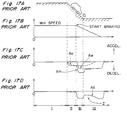
- Fig. 17A shows the state in which an automotive vehicle provided with the conventional gravitational accelerometer as described above and travelling or running at a constant speed, starts braking in the course of a downhill, and stops on a generally horizontal road continued to the downhill.
- Fig. 17B shows variation of the wheel speed.
- Fig. 17C represents variations of the vehicle acceleration Aw estimated from the wheel speed, acceleration Am based on the gravitational accelerometer, and the variable correction quantity Ao obtained for each cycle.
- Fig. 17D denotes variation of the acceleration Ac obtained from the gravitational accelerometer after correction by using the correction quantity Ao.
- a region I shows the state in which the vehicle is travelling or running on a horizontal road at a constant speed
- a region II the state in which the vehicle is running on a downhill at a constant speed
- a region III the state in which the vehicle is running on the downhill while braking
- a region IV the state in which the vehicle runs and stops on a horizontal road while braking.
- the acceleration Ac of the gravitational accelerometer corrected by using the correction quantity Ao is calculated and outputted to be undesirably small in the direction of speed reduction, and since control of a low friction coefficient (the friction coefficient is represented as ⁇ hereinafter) is effected during this period, the braking force becomes insufficient, resulting in such an inconvenience as an increase of the stopping distance.
- the zero adjuster of the conventional gravitational accelerometer follows the variation of the zero point comparatively quickly generally during running at a constant speed or in the absence of slippage or spin, but the follow-up becomes slow, for example, during braking on the way of a downhill, thus giving rise to such a problem as the increase of the stopping distance as referred to above.
- the present invention has been developed to overcome the above-described disadvantages.
- an acceleration determining system as initially defined, characterized by a road surface state detection means for detecting a generally horizontal road surface, a horizontal correction quantity output means for outputting a horizontal correction quantity, which is a correction quantity with respect to the generally horizontal road surface, in response to an output from said road surface state detection means, and said zero correction means being arranged to correct the acceleration based on one of the correction quantity and the horizontal correction quantity to compute a corrected acceleration.
- an acceleration determining system characterised by a road surface state detection means for detecting a generally horizontal road surface, a storage means for storing said correction quantity with respect to the generally horizontal road surface as a horizontal correction quantity in response to an output from said road surface state detection means, and said zero correction means being arranged to correct the acceleration based on one of the correction quantity and the horizontal correction quantity stored in said storage means to compute a corrected acceleration.
- the generally horizontal road surface is detected by the road surface state detection means in order to compute the horizontal correction quantity AoH, and during running at a constant speed or when no slippage or spin takes place, the correction quantity Ao is calculated for each specific cycle from the difference between the vehicle acceleration Aw estimated from the wheel speed and the acceleration Ac obtained from the acceleration detection means after the correction. Furthermore, the correction quantity Ao computed for each specific cycle is corrected by adding or subtracting it to or from the acceleration Am obtained from the acceleration detection means. By so doing, in the case of braking in the course of a downhill or in the case where slippage or spin is taking place, the acceleration Am obtained from the acceleration detection means is corrected using the above horizontal correction quantity AoH instead of the correction quantity Ao.
- the acceleration detection means detects the acceleration Am applied to the automotive vehicle from an amount of displacement of a weight accommodated therein.
- the horizontal correction quantity output means may be replaced by a storage means that stores the correction quantity Ao with respect to the generally horizontal road surface as the horizontal correction quantity AoH in response to an output from the road surface state detection means.
- the acceleration Am obtained from the acceleration detection means is corrected using the horizontal correction quantity AoH read out of the storage means.
- the road surface state detection means judges to have detected the generally horizontal road surface, when the estimated vehicle acceleration Aw is smaller than a predetermined upper limit value and a differential value of the correction quantity Ao is smaller than a predetermined upper limit value, and when a state in which the correction quantity Ao is greater than the horizontal correction quantity AoH stored in the storage means in a previous cycle has continued for a predetermined period of time, to thereby store the correction quantity Ao at that time in the storage means as a new horizontal correction quantity AoH.
- the road surface state detection means judges to have detected the generally horizontal road surface, when a state in which the correction quantity Ao is smaller than the horizontal correction quantity AoH stored in the storage means in a previous cycle has continued for a predetermined period of time.
- the zero correction means compares the correction quantity Ao with the horizontal correction quantity AoH and selects the greater quantity for addition to or substraction from the acceleration Am, to thereby compute the corrected acceleration Ac.
- the horizontal correction quantity AoH at that time is set to be the correction quantity Ao.
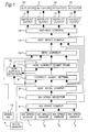
- FIG. 1 a block diagram of an anti-skid control apparatus in which a gravitational accelerometer according to the present invention is incorporated.
- the illustrated anti-skid control apparatus is applied to, for example, a four-wheel automotive vehicle.
- the anti-skid control apparatus comprises a plurality of, for example, four in the illustrated embodiment, wheel speed sensors 1, 2, 3, and 4 for detecting the speed of associated wheels, an acceleration sensor 5 for detecting and outputting the rate of acceleration applied to the vehicle body, and a wheel speed computing unit 6 for computing the wheel speed of each of the four wheels based on output signals from the wheel speed sensors 1-4.
- the acceleration sensor 5 is comprised of a gravitational acceleration sensor such as shown in Fig. 15 wherein the application of an acceleration thereto increases the output voltage thereof.
- the anti-skid control apparatus also comprises a wheel speed selector 7 for appropriately selecting any one of the maximum speed, minimum speed and average speed from among the four wheel speeds according to the running conditions, an estimated vehicle acceleration computing unit 8 for computing an estimated acceleration Aw of the vehicle body based on the wheel speed selected by the wheel speed selector 7, and a correction quantity setting unit 9 for computing a correction quantity Ao required to set the accelerometer to zero.
- a horizontal road surface detection unit 10 is provided for detecting the horizontal state of the road surface and accommodates two timers (not shown): a first timer for counting the state wherein the correction quantity Ao is greater than a horizontal correction quantity AoH; and a second timer for counting the state wherein the correction quantity Ao is equal to or smaller than the horizontal correction quantity AoH.
- the correction quantity Ao at that time is stored as the horizontal correction quantity AoH in a horizontal correction quantity storage 11.
- a zero correction unit 13 is provided for computing a corrected acceleration Ac by correcting an acceleration inputted thereto from the acceleration sensor 5. This correction depends upon the ON-OFF state of a brake switch 12, which is turned on when the brake is applied to the vehicle body.
- the anti-skid control apparatus further comprises an estimated vehicle speed computing unit 14 for computing an estimated vehicle speed, an anti-skid control unit 15 for outputting anti-lock control signals upon discrimination of locking symptoms of the wheels, a plurality of (four in the illustrated embodiment) instruction output units 16, 17, 18, and 19 for outputting signals required to control braking pressures based on the anti-lock control signals, and a plurality of (four in the illustrated embodiment) actuators 20, 21, 22, and 23 for driving associated solenoids.
- Signals from the wheel speed sensors 1-4 are inputted to the wheel speed computing unit 6 for computation of respective wheel speeds.
- the wheel speeds computed by the wheel speed computing unit 6 are inputted to the wheel speed selector 7, which in turn selects an appropriate wheel speed according to the current situation.
- the wheel speeds computed by the wheel speed computing unit 6 are also inputted to the anti-skid control unit 15.
- the wheel speed selected by the wheel speed selector 7 is inputted to the estimated vehicle acceleration computing unit 8, which in turn computes an estimated acceleration Aw of the vehicle body based on the wheel speed inputted thereto from the wheel speed selector 7.
- the wheel speed selected by the wheel speed selector 7 is also inputted to the estimated vehicle speed computing unit 14.
- the estimated vehicle acceleration Aw computed by the estimated vehicle acceleration computing unit 8 is inputted to the correction quantity setting unit 9, to the horizontal road surface detection unit 10, and to the estimated vehicle speed computing unit 14.
- the acceleration Am detected by the acceleration sensor 5 is inputted to the correction quantity setting unit 9 and to the zero correction unit 13.
- the correction quantity setting unit 9 computes the correction quantity Ao based on the corrected acceleration Ac computed by the zero correction unit 13 in the previous operation cycle, in addition to the acceleration Am inputted thereto from the acceleration sensor 5 and the estimated vehicle acceleration Aw inputted thereto from the estimated vehicle acceleration computing unit 8.
- the correction quantity Ao computed by the correction quantity setting unit 9 is inputted to the horizontal road surface detection unit 10, to which the horizontal correction quantity AoH stored in the horizontal correction quantity storage 11 in the previous cycle is also inputted. Based on the inputted data, when the horizontal road surface detection unit 10 has detected the horizontal road surface state, the correction quantity Ao at that time is stored in the horizontal correction quantity storage 11.
- the zero correction unit 13 performs a correction with respect to the acceleration Am inputted thereto from the acceleration sensor 5 by allowing either the correction quantity Ao from the correction quantity setting unit 9 or the horizontal correction quantity AoH from the horizontal correction quantity storage 11 to be inputted thereto, depending on whether an ON-signal, i.e., a braking signal, from the brake switch 12 is inputted thereto.
- an ON-signal i.e., a braking signal
- the estimated vehicle speed computing unit 14 computes the estimated vehicle speed based on either the estimated vehicle acceleration Aw computed by the estimated vehicle acceleration computing unit 8 or the corrected acceleration Ac computed by the zero correction unit 13, and a selected wheel speed Vr from the wheel speed selector 7.
- the estimated vehicle speed computed by the estimated vehicle speed computing unit 14 is inputted to the anti-skid control unit 15.
- the anti-skid control unit 15 discriminates the locking symptoms of the wheels based on the wheel speeds inputted thereto from the wheel speed computing unit 6 and the estimated vehicle speed inputted thereto from the estimated vehicle speed computing unit 14, and outputs the anti-lock control signals to the instruction output units 16-19.
- the instruction output units 16-19 Upon receiving the anti-lock control signals from the anti-skid control unit 15, the instruction output units 16-19 output to associated actuators 20-23 respective signals required to control the braking pressures.
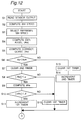
- the output Am from the acceleration sensor 5 is first read at step S1, followed by step S2 at which the wheel speeds are computed based on the outputs from the wheel speed sensors 1-4.
- the representative wheel speed Vr is selected at step S3, followed by step S4 at which the estimated vehicle acceleration Aw is computed based on the selected wheel speed Vr.
- the correction quantity setting unit 9 computes the correction quantity Ao required for the zero adjustment of the gravitational accelerometer.
- a detailed description of a calculation method of the correction quantity Ao is omitted because such a method is known in, for example, Japanese Laid-open Patent Publication (unexamined) No. 4-223275.
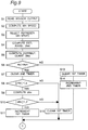
- Subsequent steps S6 to S16 indicate a flow wherein the horizontal road surface detection unit 10 detects the horizontal road surface.
- the correction quantity Ao is compared with the horizontal correction quantity AoH stored in the horizontal correction quantity storage 11. If the correction quantity Ao is greater than the horizontal correction quantity AoH, the second timer is cleared to zero at step S7.
- the horizontal correction quantity AoH used at step S6 is a value stored in the horizontal correction quantity storage 11 in the previous cycle.
- of the estimated vehicle acceleration Aw is compared with a predetermined value ⁇ , which is a sufficiently small one with which it can be determined that the vehicle body travels substantially at a constant speed. If the absolute value
- of the difference dAo computed at step S9 is compared with a predetermined value ⁇ , which is considered to be a sufficiently small one indicating no substantial change in inclination of the road surface. If the absolute value
- the counted value of the first timer is compared with a predetermined value t1. If the counted value of the first timer is greater than the predetermined value t1, the correction quantity Ao at that time is stored as the horizontal correction quantity AoH in the horizontal correction quantity storage 11 (step S17).
- step S6 in Fig. 2 if the correction quantity Ao is smaller than the horizontal correction quantity AoH stored in the horizontal correction quantity storage 11, the procedure advances to step S13 at which the first timer is cleared to zero. Then, the second timer is incremented by 1 at step S14, and the procedure advances to step S12 in Fig. 3.
- step S8 if the absolute value
- step S12 in Fig. 3 if the counted value of the first timer is equal to or smaller than the predetermined value t1, the procedure advances to step S16 at which the counted value of the second timer is compared with a predetermined value t2. If the counted value of the second timer is greater than the predetermined value t2, the procedure advances to step S17. In contrast, if the former is equal to or smaller than the latter, the procedure advances to step S18.
- Subsequent steps S18 to S21 indicate a flow wherein the zero correction unit 13 computes the corrected acceleration Ac.
- step S18 a determination is made whether the braking signal from the brake switch 12 is inputted to the zero correction unit 13. If the braking signal is inputted to the zero correction unit 13, i.e., if the brake is applied to the vehicle body, the horizontal correction quantity AoH stored in the horizontal correction quantity storage 11 is compared with the correction quantity Ao (step S19). If the horizontal correction quantity AoH is greater than the correction quantity Ao, the procedure advances to step S20 at which the corrected acceleration Ac is obtained by subtracting the horizontal correction quantity AoH from the acceleration Am detected by the acceleration sensor 5, thus terminating this flow.
- step S18 if no brake is applied to the vehicle body, the procedure advances to step S21 at which the corrected acceleration Ac is obtained by subtracting the correction quantity Ao at that time from the acceleration Am detected by the acceleration sensor 5, thus terminating this flow. Likewise, if the correction quantity Ao is equal to or greater than the horizontal correction quantity AoH stored in the horizontal correction quantity storage 11, the procedure advances to step S21.
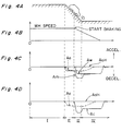
- Fig. 4A depicts an automotive vehicle having the above-described gravitational accelerometer of the present invention and travelling substantially at a constant speed, which vehicle starts braking in the course of a downhill and stops on a generally horizontal road continued to the downhill.
- Fig. 4B depicts wheel speed variation.
- Fig. 4C depicts variation in the vehicle acceleration Aw estimated from the wheel speed, variation in the acceleration Am detected by the gravitational acceleration sensor, and variations in the correction quantity Ao and the horizontal correction quantity AoH obtained for each cycle.
- Fig. 4D depicts variation in the acceleration Ac obtained from the corrected gravitational acceleration sensor.
- a region denoted by I indicates the state in which the vehicle is travelling on a generally horizontal road substantially at a constant speed
- a region denoted by II indicates the state in which the vehicle is travelling on the downhill substantially at the constant speed
- a region denoted by III indicates the state in which the vehicle is travelling on the downhill while the brake is being applied thereto
- a region denoted by IV indicates the state in which the vehicle is travelling on a generally horizontal road and eventually stops while the brake is being applied thereto.
- the travelling on the horizontal road surface is detected by the horizontal road surface detection unit 10, and the horizontal correction quantity AoH for the travelling on the horizontal road surface is stored in the horizontal correction quantity storage 11.
- the corrected acceleration Ac is obtained by subtracting the horizontal correction quantity AoH from the acceleration Am detected by the acceleration sensor 5.
- the corrected acceleration Ac is computed by subtracting the correction quantity Ao from the acceleration Am detected by the acceleration sensor 5.
- the corrected acceleration Ac is computed by subtracting the horizontal correction quantity AoH stored in the horizontal correction quantity storage 11, instead of the correction quantity Ao, from the acceleration Am detected by the acceleration sensor 5.
- the acceleration Ac after the correction computed in the above described manner will be as shown in Fig. 4D, and thus, there is no possibility that the corrected acceleration Ac by the acceleration sensor 5 as shown in an arrow Z in Fig. 17D is undesirably computed to be small in the direction of speed reduction, and such inconveniences that control in the low ⁇ is effected during this period, resulting in insufficient braking force and consequent extension of the stopping distance, etc. can be advantageously eliminated.
- the corrected acceleration Ac may be computed by subtracting the correction quantity Ao from the acceleration Am based on the acceleration sensor 5.
- a gravitational acceleration sensor as shown in Fig. 16 in which the output voltage is reduced upon acceleration.
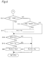
- Figs. 5 and 6 depict flow-charts indicating the operation of the gravitational accelerometer according to a modification of the first embodiment in which the acceleration sensor shown in Fig. 16 is incorporated.
- step S6' in the flow-chart of Fig. 5
- step S19' in the flow-chart of Fig. 6.
- step S6' the correction quantity Ao of the accelerometer is compared with the horizontal correction quantity AoH stored in the horizontal correction quantity storage 11. If the correction quantity Ao is smaller than the horizontal correction quantity AoH, the second timer is cleared to zero at step S7. Meanwhile, if the correction quantity Ao is greater than the horizontal correction quantity AoH stored in the horizontal correction quantity storage 11, the procedure advances to step S13.
- the horizontal correction quantity AoH stored in the horizonal correction quantity storage 11 is compared with the correction quantity Ao. If the horizontal correction quantity AoH is smaller than the zero correction quantity Ao, the procedure advances to step S20. In contrast, if the correction quantity Ao is greater than the horizontal correction quantity AoH stored in the horizontal correction quantity storage 11, the procedure proceeds to step 21.
- Fig. 7A shows the state wherein an automotive vehicle provided with a gravitational accelerometer having the gravitational acceleration sensor in which the output voltage is decreased upon acceleration as shown in Fig. 16, and travelling at a constant speed, starts braking in the course of a downhill and stops on a generally horizontal road after the end of the downhill.
- Fig. 7B shows variation of the wheel speed.
- Fig. 7C represents variations of the vehicle acceleration Aw estimated by the wheel speed, acceleration Am based on the gravitational acceleration sensor, variable zero correction quantity Ao obtained for each cycle, and the horizontal correction quantity AoH.
- Fig. 7D denotes variation of the acceleration Ac obtained from the gravitational acceleration sensor after the correction.
- the difference of the above diagrams from those of the first embodiment resides in that, since the output voltage with respect to the acceleration shows a negative characteristic in the acceleration sensor, the acceleration Am based on the acceleration sensor indicates a positive value, and thus, the variation reversed in the positive and negative characteristics is shown.
- the zero correction quantity Ao and horizontal correction quantity AoH similarly show variations reversed in the positive and negative characteristics, but the function and effect similar to those in the first embodiment can be obtained.
- Fig. 8 shows a block diagram of the anti-skid control apparatus according to the second embodiment of the present invention
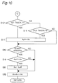
- Figs. 9 and 10 are flow-charts representing functioning for effecting the zero correction of the accelerometer according to the second embodiment.
- the difference in the circuit arrangement from that of the first embodiment is such that the brake-on signal by the brake switch 12 is applied not to the zero correction unit 13, but to the correction quantity setting unit 9, and further, the horizontal correction quantity AoH stored in the horizontal correction quantity storage 11 is inputted not to the zero correction unit 13, but to the correction quantity setting unit 9.
- the correction quantity setting unit 9 substitutes the value of the horizontal correction quantity AoH stored in the horizontal correction quantity storage 11, for the correction quantity Ao by the correction quantity setting unit 9 only for said moment, i.e. oily during one cycle for effecting the zero correction of the accelerometer.
- step S50 a signal from the brake switch 12 indicating the presence or absence of braking is inputted to the correction quantity setting unit 9, and if starting of braking of the vehicle is detected, the horizontal correction quantity AoH stored in the horizontal correction quantity storage 11 is compared with the correction quantity Ao. If the horizontal correction quantity AoH is greater than the correction quantity Ao, the procedure advances to step S51.
- the correction quantity setting unit 9 outputs the horizontal correction quantity AoH stored in the horizontal correction quantity storage 11 as the correction quantity Ao.
- the acceleration Ac after the correction is computed by subtracting the correction quantity Ao equal in value to the horizontal correction quantity AoH stored in the horizontal correction quantity storage 11, from the acceleration Am based on the acceleration sensor 5, at the zero correction unit 13, to thereby complete this flow.
- step S50 if the starting of braking for the vehicle is not detected, the procedure advances to step S52.
- the zero correction unit 13 by subtracting the correction quantity Ao computed by the predetermined calculation at the correction quantity setting unit 9, from the acceleration Am based on the acceleration sensor 5, the acceleration Ac after the correction is computed, to thereby complete this flow.
- step S19 if the horizontal correction quantity AoH stored in the horizontal correction quantity storage 11 is smaller than the correction quantity Ao computed by the correction quantity setting unit 9, the procedure advances to step S52.
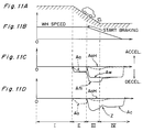
- Fig. 11A shows the state in which the automotive vehicle provided with the gravitational accelerometer according to the second embodiment of the present invention and running at a constant speed, starts braking in the course of a downhill, and stops on a generally horizontal road after the end of the downhill.
- Fig. 11B shows variation of the wheel speed.
- Fig. 11C represents variations of the vehicle acceleration Aw estimated by the wheel speed, acceleration Am based on the gravitational acceleration sensor 5, and variable zero correction quantity Ao obtained for each cycle, and the horizontal correction quantity AoH.
- Fig. 11D denotes variation of the acceleration Ac obtained from the acceleration sensor 5 after the correction.
- the correction quantity Ao becomes equal in value to the horizontal correction quantity AoH at the starting of the braking. Thereafter, at, the first half of the braking, i.e. in the region III, since the automotive vehicle is located on the downhill, the correction quantity Ao changes so as to slowly correct the inclination component of the downhill, and also, slowly approaches zero at the portion where the vehicle has been transferred onto the horizontal road, i.e. in the region IV.
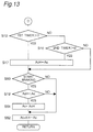
- Figs. 12 and 13 depict flow-charts indicating the operation of the gravitational accelerometer according to a modification of the second embodiment, which is internally provided with the acceleration sensor shown in Fig. 16 in which the output voltage is decreased upon acceleration.
- step S6' in the flow-chart of Fig. 12
- step S19' in the flow-chart of Fig. 13.
- step S6' the zero correction quantity Ao of the accelerometer is compared with the horizontal correction quantity AoH stored in the horizontal correction quantity storage 11. If the correction quantity Ao is smaller than the horizontal correction quantity AoH, the second timer is cleared to zero at step S7. In contrast, if the correction quantity Ao is greater than the horizontal correction quantity AoH stored in the horizontal correction quantity storage 11, the procedure advances to step S13.
- step 19' the horizontal correction quantity AoH stored in the horizonal correction quantity storage 11 is compared with the correction quantity Ao, and if the horizontal correction quantity AoH is smaller than the correction quantity Ao, the procedure advances to step S51. If the horizontal correction quantity AoH stored in the horizontal correction quantity storage 11 is greater than the correction quantity Ao computed by the correction quantity setting unit 9, the procedure advances to step S52.
- Fig. 14A shows the state in which an automotive vehicle provided with a gravitational accelerometer having the gravitational acceleration sensor in which the output voltage is decreased upon acceleration as shown in Fig. 16, and travelling at a constant speed, starts braking in the course of a downhill and stops on a generally horizontal road after the end of the downhill.
- Fig. 14B shows variation of the wheel speed.
- Fig. 14C represents variations of the vehicle acceleration Aw estimated by the wheel speed, acceleration Am based on the gravitational acceleration sensor, variable zero correction quantity Ao obtained for each cycle, and the horizontal correction quantity AoH.
- Fig. 14D denotes variation of the acceleration Ac obtained from the gravitational acceleration sensor after the correction.
- the difference of the above diagrams from those of the second embodiment resides in that, since the output voltage with respect to the acceleration shows a negative characteristic in the acceleration sensor, the acceleration Am based on the acceleration sensor indicates a positive value, and thus, the variation reversed in the positive and negative characteristics is shown with respect to the second embodiment. Since the estimated vehicle acceleration Aw also shows the variation reversed in the positive and negative characteristics with respect to the second embodiment, the correction quantity Ao and horizontal correction quantity AoH also show variations reversed in the positive and negative characteristics with respect to the second embodiment. However, the function and effect similar to those in the second embodiment can be obtained.
- the acceleration determining system disclosed herein even when it is subjected to somewhat long-term variations due to, for example, fixing accuracy, electrical drift, and gain fluctuation, etc. of the gravitational acceleration sensor, or to influences by the inclination or gradient of the road surface, the zero correction and sensitivity correction thereof can be quickly effected. Furthermore, in the cases of sudden changes in the road surface inclination or braking in the course of a downhill or slope, there is no possibility that follow-up of the zero correction is delayed, and thus, such a problem as extension of the stopping distance, etc. can be eliminated. Accordingly, acceleration at high accuracy may be obtained for still more accurate control of automotive vehicles.
- the described acceleration determining system is capable of effecting more accurate control of the vehicle by achieving acceleration with a high follow-up accuracy for zero correction with respect to rapid variations in the inclination of a road surface or during braking in the course of a downhill or the like.
- it is stable and reliable in functioning, and can be readily incorporated into automotive vehicles of various types at a low cost.
Claims (9)
- Système de détermination d'une accélération, à utiliser dans un véhicule automobile, le système comportant:un moyen (1-4) de délivrance d'un signal de vitesse de roue, pour délivrer un signal de vitesse de roue en mesurant une vitesse de rotation d'au moins l'une des roues du véhicule;un moyen (5) de détection d'une accélération, comportant un accéléromètre gravitationnel pour détecter et délivrer une accélération Am appliquée au véhicule automobile;un moyen (8) de délivrance d'une accélération estimée du véhicule, pour délivrer un signal d'accélération estimée Aw du véhicule, estimée à partir de la vitesse de roue;un moyen (9) de calcul d'une grandeur de correction, pour calculer une grandeur de correction variable Ao pour chaque cycle de calcul; etun moyen (13) de correction du zéro pour corriger l'accélération Am;
caractérisé par:un moyen (10) de détection de l'état de surface d'une route, pour détecter une surface de route généralement horizontale;un moyen (11) de délivrance d'une grandeur de correction horizontale, pour délivrer une grandeur de correction horizontale AoH, qui est une grandeur de correction par rapport à la surface généralement horizontale de la route, en réponse à une sortie dudit moyen (10) de détection de l'état de surface de la route; etledit moyen (13) de correction du zéro étant agencé pour corriger l'accélération Am sur base de l'une parmi la grandeur de correction Ao et la grandeur de correction horizontale AoH, pour calculer une accélération corrigée Ac. - Système de détermination d'une accélération à utiliser dans un véhicule automobile, le système comportant :un moyen (1-4) de délivrance d'un signal de vitesse de roue pour délivrer un signal de vitesse de roue en mesurant une vitesse de rotation d'au moins l'une des roues du véhicule;un moyen (5) de détection d'une accélération, comportant un accéléromètre gravitationnel pour détecter et délivrer une accélération Am appliquée au véhicule automobile;un moyen (8) de délivrance d'un signal d'accélération estimée du véhicule, pour délivrer un signal d'accélération estimée Aw du véhicule, estimée à partir de la vitesse de roue;un moyen (9) de calcul d'une grandeur de correction, pour calculer une grandeur variable de correction Ao pour chaque cycle de calcul; etun moyen (13) de correction du zéro pour corriger l'accélération Am;
caractérisé par:un moyen (10) de détection de l'état de surface de la route, pour détecter une surface de route généralement horizontale;un moyen de mémorisation (11) pour conserver ladite grandeur de correction Ao par rapport à la surface généralement horizontale de la route en tant que grandeur de correction horizontale AoH en réponse à un signal de sortie dudit moyen (10) de détection de l'état de surface de la route; etledit moyen (13) de correction du zéro étant agencé pour corriger l'accélération Am sur base de l'une parmi la grandeur de correction Ao et la grandeur de correction horizontale AoH conservée dans ledit moyen de mémorisation (11), pour calculer une accélération corrigée Ac. - Système de détermination d'une accélération selon la revendication 2, dans lequel ledit moyen (5) de détection d'une accélération sert à détecter et délivrer une accélération Am appliquée au véhicule automobile à partir d'une grandeur de déplacement d'un poids (F) qui y est placé.
- Système de détermination d'une accélération selon la revendication 2 ou 3, dans lequel ledit moyen (10) de détection de l'état de surface de la route est agencé pour décider qu'il a détecté la surface généralement horizontale de la route lorsque l'accélération estimée du véhicule Aw est inférieure à une valeur limite supérieure prédéterminée et qu'une valeur différentielle de la grandeur de correction Ao est inférieure à une valeur limite supérieure prédéterminée, et lorsqu'un état dans lequel la grandeur de correction Ao est supérieure à la grandeur de correction horizontale AoH conservée dans ledit moyen de mémorisation (11) au cours d'un cycle précédent s'est maintenue pendant une durée prédéterminée, pour ainsi conserver la grandeur de correction Ao à ce moment dans ledit moyen de mémorisation (11) en tant que nouvelle grandeur de correction horizontale AoH.
- Système de détermination d'une accélération selon la revendication 2 ou 3, dans lequel ledit moyen (10) de détection de l'état de surface de la route est agencé pour décider qu'il a détecté la surface généralement horizontale de la route lorsque l'accélération estimée du véhicule Aw est inférieure à une valeur limite supérieure prédéterminée et qu'une valeur différentielle de la grandeur de correction Ao est inférieure à une valeur limite supérieure prédéterminée, et lorsqu'un état dans lequel la grandeur de correction Ao est inférieure à la grandeur de correction horizontale AoH conservée dans ledit moyen de mémorisation (11) au cours d'un cycle précédent s'est maintenue pendant une durée prédéterminée, pour ainsi conserver la grandeur de correction Ao à ce moment dans ledit moyen de mémorisation (11) comme étant une nouvelle grandeur de correction horizontale AoH.
- Système de détermination d'une accélération selon la revendication 2 ou 3, dans lequel ledit moyen (10) de détection de l'état de surface de la route est agencé pour décider qu'il a détecté la surface généralement horizontale de la route lorsqu'un état dans lequel la grandeur de correction Ao est inférieure à la grandeur de correction horizontale AoH conservée dans ledit moyen de mémorisation (11) dans un cycle précédent s'est maintenue pendant une durée prédéterminée, pour ainsi conserver la grandeur de correction Ao à ce moment dans ledit moyen de mémorisation (11) comme étant une nouvelle grandeur de correction horizontale AoH.
- Système de détermination d'une accélération selon la revendication 2 ou 3, dans lequel ledit moyen (10) de détection de l'état de surface de la route est agencé pour décider qu'il a détecté la surface généralement horizontale de la route lorsqu'un état dans lequel la grandeur de correction Ao est supérieure à la grandeur de correction horizontale AoH conservée dans ledit moyen de mémorisation (11) au cours d'un cycle précédent s'est maintenue pendant une durée prédéterminée, pour ainsi conserver la grandeur de correction Ao à ce moment dans ledit moyen de mémorisation (11) comme étant une nouvelle grandeur de correction horizontale AoH.
- Système de détermination d'une accélération selon la revendication 2 ou 3 dans lequel ledit moyen (13) de correction du zéro est agencé pour comparer, pendant un freinage, la grandeur de correction Ao à la grandeur de correction horizontale AoH, et pour choisir la plus grande grandeur pour l'ajouter à, ou la soustraire de l'accélération Am, pour ainsi calculer l'accélération corrigée Ac.
- Système de détermination d'une accélération selon la revendication 2 ou 3, dans lequel, au début d'un freinage, lorsque la grandeur de correction horizontale AoH est supérieure à la grandeur de correction Ao, la grandeur de correction horizontale AoH à ce moment est fixée comme étant la grandeur de correction Ao.
Applications Claiming Priority (2)
| Application Number | Priority Date | Filing Date | Title |
|---|---|---|---|
| JP308949/93 | 1993-12-09 | ||
| JP30894993A JP3319101B2 (ja) | 1993-12-09 | 1993-12-09 | 車両の重力式加速度計 |
Publications (2)
| Publication Number | Publication Date |
|---|---|
| EP0657333A1 EP0657333A1 (fr) | 1995-06-14 |
| EP0657333B1 true EP0657333B1 (fr) | 1998-08-05 |
Family
ID=17987196
Family Applications (1)
| Application Number | Title | Priority Date | Filing Date |
|---|---|---|---|
| EP94119325A Expired - Lifetime EP0657333B1 (fr) | 1993-12-09 | 1994-12-07 | Système de détermination d'accélération comprenant un accéléromètre à gravité avec ajustement du point zéro |
Country Status (5)
| Country | Link |
|---|---|
| US (1) | US5526263A (fr) |
| EP (1) | EP0657333B1 (fr) |
| JP (1) | JP3319101B2 (fr) |
| KR (1) | KR0139592B1 (fr) |
| DE (1) | DE69412216T2 (fr) |
Families Citing this family (31)
| Publication number | Priority date | Publication date | Assignee | Title |
|---|---|---|---|---|
| US6516284B2 (en) * | 1994-11-21 | 2003-02-04 | Phatrat Technology, Inc. | Speedometer for a moving sportsman |
| US7386401B2 (en) | 1994-11-21 | 2008-06-10 | Phatrat Technology, Llc | Helmet that reports impact information, and associated methods |
| US6308134B1 (en) | 1996-12-27 | 2001-10-23 | Magellan Dis, Inc. | Vehicle navigation system and method using multiple axes accelerometer |
| KR19990062746A (ko) * | 1997-12-24 | 1999-07-26 | 모찌즈키 아키히로 | 쥐센서의 출력치 보정 및 이상 검출 |
| JPH11248743A (ja) * | 1998-02-27 | 1999-09-17 | Toyota Motor Corp | 車載前後加速度センサの零点較正装置 |
| DE19825304A1 (de) * | 1998-06-05 | 1999-12-09 | Bayerische Motoren Werke Ag | Radbremsregelsystem für Kraftfahrzeuge |
| US6532419B1 (en) | 1998-09-23 | 2003-03-11 | Magellan Dis, Inc. | Calibration of multi-axis accelerometer in vehicle navigation system |
| WO2000052481A1 (fr) * | 1999-02-27 | 2000-09-08 | Continental Teves Ag & Co. Ohg | Procede et dispositif de determination de la vitesse de reference d'un vehicule et de detection d'une vitesse de reference inappropriee d'un vehicule toutes roues motrices |
| US6466887B1 (en) | 1999-03-03 | 2002-10-15 | Richard L. Weinbrenner | Gravimetric rotation sensors: dead reckoning, velocity, and heading sensor system for vehicle navigation systems |
| JP3482930B2 (ja) * | 1999-11-26 | 2004-01-06 | 三菱ふそうトラック・バス株式会社 | 勾配車両加速度センサの補正装置 |
| JP2002022766A (ja) * | 2000-07-07 | 2002-01-23 | Hino Motors Ltd | センサの故障判定装置 |
| US7316288B1 (en) * | 2003-01-27 | 2008-01-08 | Polaris Industries Inc. | All terrain vehicle with multiple steering modes |
| DE102005029587B4 (de) | 2004-07-22 | 2020-08-06 | Schaeffler Technologies AG & Co. KG | Verfahren und Einrichtung zum Steuern eines Antriebstrangs eines Fahrzeugs |
| FR2878954B1 (fr) * | 2004-12-07 | 2007-03-30 | Sagem | Systeme de navigation inertielle hybride base sur un modele cinematique |
| JP2006176084A (ja) * | 2004-12-24 | 2006-07-06 | Advics:Kk | 車両挙動センサの検出値補正方法 |
| US20060169021A1 (en) * | 2005-01-28 | 2006-08-03 | Silverstein D A | Method and apparatus for calibration of a motion sensing device in a portable apparatus |
| JP4556945B2 (ja) * | 2006-12-07 | 2010-10-06 | 日産自動車株式会社 | 加速度検出装置および加速度センサのドリフト誤差補正方法ならびにそれを用いたニュートラル制御装置 |
| US20090254274A1 (en) * | 2007-07-27 | 2009-10-08 | Kulik Victor | Navigation system for providing celestial and terrestrial information |
| FR2926210A1 (fr) * | 2008-01-14 | 2009-07-17 | Dental Revolution Ltd | Brosse a dents a double systeme rotatif de brossage |
| JP4503078B2 (ja) * | 2008-02-04 | 2010-07-14 | 日本テキサス・インスツルメンツ株式会社 | タイヤ回転検出装置、タイヤ回転検出方法及びタイヤ監視装置 |
| DE102008009522B4 (de) * | 2008-02-16 | 2021-12-16 | Zf Cv Systems Hannover Gmbh | Verfahren zur Kalibrierung von Radgeschwindigkeiten |
| WO2010097897A1 (fr) * | 2009-02-25 | 2010-09-02 | トヨタ自動車株式会社 | Appareil et procédé de commande pour véhicule |
| DE102010004113B4 (de) * | 2010-01-07 | 2014-11-20 | Continental Automotive Gmbh | Verfahren und Vorrichtung zur Ermittlung eines maximalen Reibungsbeiwerts μmax zwischen einem Reifen und einem Untergrund |
| US8498785B2 (en) * | 2010-09-07 | 2013-07-30 | Trw Automotive U.S. Llc | Method and apparatus for determining tire position on a vehicle |
| US8498759B1 (en) | 2012-02-20 | 2013-07-30 | Trw Automotive U.S. Llc | Method and apparatus for determining a condition and relative location of an inner tire and an outer tire of a tire pair |
| US9612255B2 (en) * | 2013-02-20 | 2017-04-04 | Northrop Grumman Guidance And Electronic Company, Inc. | Range-dependent bias calibration of an accelerometer sensor system |
| US9612256B2 (en) * | 2013-02-20 | 2017-04-04 | Northrop Grumman Guidance And Electronics Company, Inc. | Range-dependent bias calibration of an accelerometer sensor system |
| DE102014207628A1 (de) | 2014-04-23 | 2015-10-29 | Continental Teves Ag & Co. Ohg | Verfahren zur Ermittlung eines Offsets eines Inertialsensors |
| KR101601104B1 (ko) * | 2014-09-22 | 2016-03-08 | 현대자동차주식회사 | G센서를 이용한 도로 구배 연산 장치 및 방법 |
| CN110440827B (zh) * | 2019-08-01 | 2022-05-24 | 北京神导科讯科技发展有限公司 | 一种参数误差的标定方法、装置及存储介质 |
| US11427209B2 (en) | 2020-04-30 | 2022-08-30 | Ford Global Technologies, Llc | Systems and methods for vehicle speedometer calibration |
Family Cites Families (16)
| Publication number | Priority date | Publication date | Assignee | Title |
|---|---|---|---|---|
| US3824386A (en) * | 1972-05-04 | 1974-07-16 | Hollandse Signaalapparaten Bv | Apparatus for determining the momentary tilt of a vehicle or craft |
| JPS5245879B2 (fr) * | 1972-05-15 | 1977-11-18 | ||
| US4033635A (en) * | 1974-03-13 | 1977-07-05 | Fabrica Espanola Magnetos, S.A. | Electronic control devices applicable to anti-skid equipment in automobile vehicles |
| US4089564A (en) * | 1974-03-18 | 1978-05-16 | Saab-Scania Aktiebolag | Method and apparatus for predicting vehicle speed in braking control systems for wheeled vehicles |
| US4003241A (en) * | 1974-07-19 | 1977-01-18 | General Electric Company | Accelerometer method of indicating rolling resistance of a vehicle |
| US3916697A (en) * | 1974-10-15 | 1975-11-04 | Us Navy | Accelerometer tilt error compensator |
| CA1085645A (fr) * | 1978-07-06 | 1980-09-16 | Henry O. Baker | Accelerometre portatif |
| US4410154A (en) * | 1979-06-25 | 1983-10-18 | Westinghouse Electric Corp. | Transit vehicle brake control apparatus and method |
| GB8513686D0 (en) * | 1985-05-30 | 1985-07-03 | Lucas Ind Plc | Vehicle braking system |
| FR2608545B1 (fr) * | 1986-12-19 | 1990-08-31 | Peugeot | Dispositif de correction de l'angle d'attitude d'un vehicule automobile |
| US4852950A (en) * | 1987-09-16 | 1989-08-01 | Toyota Jidosha Kabushiki Kaisha | Vehicle braking system capable of preventing rock-back motion of driver/passenger upon vehicle stopping |
| DE3933652A1 (de) * | 1989-10-09 | 1991-04-11 | Bosch Gmbh Robert | Antiblockierregelsystem und antriebsschlupfregelsystem |
| JP3030866B2 (ja) * | 1990-12-26 | 2000-04-10 | 住友電気工業株式会社 | 重力式加速度計の零点補正装置 |
| JP3030867B2 (ja) * | 1990-12-27 | 2000-04-10 | 住友電気工業株式会社 | 車体運動方向の推定装置 |
| JP3662596B2 (ja) * | 1991-01-14 | 2005-06-22 | 住友電気工業株式会社 | 推定車体速度等の算出装置 |
| US5176431A (en) * | 1991-06-27 | 1993-01-05 | Allied-Signal Inc. | Vehicle deceleration prediction based on vehicle dive |
-
1993
- 1993-12-09 JP JP30894993A patent/JP3319101B2/ja not_active Expired - Fee Related
-
1994
- 1994-12-02 US US08/353,238 patent/US5526263A/en not_active Expired - Lifetime
- 1994-12-07 EP EP94119325A patent/EP0657333B1/fr not_active Expired - Lifetime
- 1994-12-07 DE DE69412216T patent/DE69412216T2/de not_active Expired - Fee Related
- 1994-12-09 KR KR1019940033432A patent/KR0139592B1/ko not_active IP Right Cessation
Also Published As
| Publication number | Publication date |
|---|---|
| KR950019739A (ko) | 1995-07-24 |
| KR0139592B1 (ko) | 1998-07-15 |
| EP0657333A1 (fr) | 1995-06-14 |
| DE69412216D1 (de) | 1998-09-10 |
| DE69412216T2 (de) | 1999-01-21 |
| US5526263A (en) | 1996-06-11 |
| JP3319101B2 (ja) | 2002-08-26 |
| JPH07159431A (ja) | 1995-06-23 |
Similar Documents
| Publication | Publication Date | Title |
|---|---|---|
| EP0657333B1 (fr) | Système de détermination d'accélération comprenant un accéléromètre à gravité avec ajustement du point zéro | |
| EP0492642B1 (fr) | Dispositif d'estimation de la direction d'avancement d'un véhicule | |
| KR920002436B1 (ko) | 차량의 가속 슬립방지장치 | |
| EP0322911B1 (fr) | Appareil de calcul de vitesse de référence de roue | |
| US5001636A (en) | Yaw motion control device | |
| EP0492626B1 (fr) | Appareil de correction du point zéro pour un accéléromètre à gravité | |
| EP0496252B1 (fr) | Appareil pour calculer une vitesse et une accélération estimées | |
| US5092662A (en) | Anti-lock control method and apparatus for vehicle | |
| EP0943517B1 (fr) | Dispositif pour la détermination de l'angle de pente d'un véhicule | |
| EP0442500A2 (fr) | Estimation du coefficient de friction d'une route | |
| US5150299A (en) | Antilock wheel speed control device having first and second brake pressure controllers | |
| EP0568204B1 (fr) | Procédé et dispositif d'estimation de friction de surface | |
| US5251970A (en) | Method of controlling the brake pressure in an anti-lock vehicle brake system | |
| JP2691210B2 (ja) | 四輪駆動車加速時の車両速度推定方法 | |
| JP3843798B2 (ja) | 車両用舵角検出装置 | |
| JP3555200B2 (ja) | アンチスキッド制御装置 | |
| US5233529A (en) | Automatic anti-skid brake control system | |
| JP3318942B2 (ja) | 推定車体速度等の算出装置 | |
| JPH063368A (ja) | 車体加減速度検出手段の零点補正装置 | |
| JP2524172B2 (ja) | 車両のヨ―運動制御装置 | |
| JP2524171B2 (ja) | 車両のヨ―運動制御装置 | |
| JP4674959B2 (ja) | 路面状態推定装置 | |
| JP3449031B2 (ja) | 自動変速機の制御装置 | |
| JPH0370657B2 (fr) | ||
| JP3803119B2 (ja) | アンチスキッド制御装置 |
Legal Events
| Date | Code | Title | Description |
|---|---|---|---|
| PUAI | Public reference made under article 153(3) epc to a published international application that has entered the european phase |
Free format text: ORIGINAL CODE: 0009012 |
|
| AK | Designated contracting states |
Kind code of ref document: A1 Designated state(s): DE GB |
|
| 17P | Request for examination filed |
Effective date: 19950616 |
|
| 17Q | First examination report despatched |
Effective date: 19960625 |
|
| GRAG | Despatch of communication of intention to grant |
Free format text: ORIGINAL CODE: EPIDOS AGRA |
|
| GRAG | Despatch of communication of intention to grant |
Free format text: ORIGINAL CODE: EPIDOS AGRA |
|
| GRAH | Despatch of communication of intention to grant a patent |
Free format text: ORIGINAL CODE: EPIDOS IGRA |
|
| GRAH | Despatch of communication of intention to grant a patent |
Free format text: ORIGINAL CODE: EPIDOS IGRA |
|
| GRAA | (expected) grant |
Free format text: ORIGINAL CODE: 0009210 |
|
| AK | Designated contracting states |
Kind code of ref document: B1 Designated state(s): DE GB |
|
| REF | Corresponds to: |
Ref document number: 69412216 Country of ref document: DE Date of ref document: 19980910 |
|
| PLBE | No opposition filed within time limit |
Free format text: ORIGINAL CODE: 0009261 |
|
| STAA | Information on the status of an ep patent application or granted ep patent |
Free format text: STATUS: NO OPPOSITION FILED WITHIN TIME LIMIT |
|
| 26N | No opposition filed | ||
| REG | Reference to a national code |
Ref country code: GB Ref legal event code: IF02 |
|
| PGFP | Annual fee paid to national office [announced via postgrant information from national office to epo] |
Ref country code: GB Payment date: 20061206 Year of fee payment: 13 |
|
| PGFP | Annual fee paid to national office [announced via postgrant information from national office to epo] |
Ref country code: DE Payment date: 20071129 Year of fee payment: 14 |
|
| GBPC | Gb: european patent ceased through non-payment of renewal fee |
Effective date: 20071207 |
|
| PG25 | Lapsed in a contracting state [announced via postgrant information from national office to epo] |
Ref country code: GB Free format text: LAPSE BECAUSE OF NON-PAYMENT OF DUE FEES Effective date: 20071207 |
|
| PG25 | Lapsed in a contracting state [announced via postgrant information from national office to epo] |
Ref country code: DE Free format text: LAPSE BECAUSE OF NON-PAYMENT OF DUE FEES Effective date: 20090701 |