EP0656532B1 - Wärmequellendetektor - Google Patents
Wärmequellendetektor Download PDFInfo
- Publication number
- EP0656532B1 EP0656532B1 EP94118882A EP94118882A EP0656532B1 EP 0656532 B1 EP0656532 B1 EP 0656532B1 EP 94118882 A EP94118882 A EP 94118882A EP 94118882 A EP94118882 A EP 94118882A EP 0656532 B1 EP0656532 B1 EP 0656532B1
- Authority
- EP
- European Patent Office
- Prior art keywords
- infrared
- heat source
- gravity
- center
- sensing elements
- Prior art date
- Legal status (The legal status is an assumption and is not a legal conclusion. Google has not performed a legal analysis and makes no representation as to the accuracy of the status listed.)
- Expired - Lifetime
Links
- 230000005484 gravity Effects 0.000 claims description 67
- 238000006073 displacement reaction Methods 0.000 claims description 25
- 238000001514 detection method Methods 0.000 claims description 19
- 239000000284 extract Substances 0.000 claims description 4
- 239000013598 vector Substances 0.000 description 18
- 230000005855 radiation Effects 0.000 description 17
- 238000010586 diagram Methods 0.000 description 11
- 238000000034 method Methods 0.000 description 9
- XUIMIQQOPSSXEZ-UHFFFAOYSA-N Silicon Chemical compound [Si] XUIMIQQOPSSXEZ-UHFFFAOYSA-N 0.000 description 4
- 229910052710 silicon Inorganic materials 0.000 description 4
- 239000010703 silicon Substances 0.000 description 4
- 230000002123 temporal effect Effects 0.000 description 4
- 230000014509 gene expression Effects 0.000 description 3
- IJGRMHOSHXDMSA-UHFFFAOYSA-N Atomic nitrogen Chemical compound N#N IJGRMHOSHXDMSA-UHFFFAOYSA-N 0.000 description 2
- 238000004519 manufacturing process Methods 0.000 description 2
- 238000012986 modification Methods 0.000 description 2
- 230000004048 modification Effects 0.000 description 2
- 229910000661 Mercury cadmium telluride Inorganic materials 0.000 description 1
- 230000002411 adverse Effects 0.000 description 1
- 239000000919 ceramic Substances 0.000 description 1
- 230000000694 effects Effects 0.000 description 1
- 238000005286 illumination Methods 0.000 description 1
- WPYVAWXEWQSOGY-UHFFFAOYSA-N indium antimonide Chemical compound [Sb]#[In] WPYVAWXEWQSOGY-UHFFFAOYSA-N 0.000 description 1
- 239000007788 liquid Substances 0.000 description 1
- 229910052757 nitrogen Inorganic materials 0.000 description 1
- 230000003287 optical effect Effects 0.000 description 1
- 230000002093 peripheral effect Effects 0.000 description 1
- 239000004065 semiconductor Substances 0.000 description 1
Images


Classifications
-
- G—PHYSICS
- G01—MEASURING; TESTING
- G01S—RADIO DIRECTION-FINDING; RADIO NAVIGATION; DETERMINING DISTANCE OR VELOCITY BY USE OF RADIO WAVES; LOCATING OR PRESENCE-DETECTING BY USE OF THE REFLECTION OR RERADIATION OF RADIO WAVES; ANALOGOUS ARRANGEMENTS USING OTHER WAVES
- G01S3/00—Direction-finders for determining the direction from which infrasonic, sonic, ultrasonic, or electromagnetic waves, or particle emission, not having a directional significance, are being received
- G01S3/78—Direction-finders for determining the direction from which infrasonic, sonic, ultrasonic, or electromagnetic waves, or particle emission, not having a directional significance, are being received using electromagnetic waves other than radio waves
- G01S3/782—Systems for determining direction or deviation from predetermined direction
- G01S3/783—Systems for determining direction or deviation from predetermined direction using amplitude comparison of signals derived from static detectors or detector systems
- G01S3/784—Systems for determining direction or deviation from predetermined direction using amplitude comparison of signals derived from static detectors or detector systems using a mosaic of detectors
-
- G—PHYSICS
- G01—MEASURING; TESTING
- G01J—MEASUREMENT OF INTENSITY, VELOCITY, SPECTRAL CONTENT, POLARISATION, PHASE OR PULSE CHARACTERISTICS OF INFRARED, VISIBLE OR ULTRAVIOLET LIGHT; COLORIMETRY; RADIATION PYROMETRY
- G01J5/00—Radiation pyrometry, e.g. infrared or optical thermometry
- G01J2005/0077—Imaging
-
- Y—GENERAL TAGGING OF NEW TECHNOLOGICAL DEVELOPMENTS; GENERAL TAGGING OF CROSS-SECTIONAL TECHNOLOGIES SPANNING OVER SEVERAL SECTIONS OF THE IPC; TECHNICAL SUBJECTS COVERED BY FORMER USPC CROSS-REFERENCE ART COLLECTIONS [XRACs] AND DIGESTS
- Y10—TECHNICAL SUBJECTS COVERED BY FORMER USPC
- Y10S—TECHNICAL SUBJECTS COVERED BY FORMER USPC CROSS-REFERENCE ART COLLECTIONS [XRACs] AND DIGESTS
- Y10S250/00—Radiant energy
- Y10S250/01—Passive intrusion detectors
Definitions
- the present invention relates to a heat source detector which detects a position of an infrared heat source such as a human body and a moving direction of a heat source position.
- an infrared sensor detects a heat source by using a passive method in which light is not irradiated on a measuring object such as a human body and radiation light spontaneously emitted from a heat source is detected. Therefore, the heat source detection can be conducted without adversely affecting the measuring object such as a human body, and without illumination even during the night. Consequently, such a detection using an infrared sensor has a wide variety of applications.
- Fig. 1 shows an example of a heat source detector using an infrared sensor.
- the heat source detector comprises a pyroelectric infrared sensor 1.
- a shield plate 18 having an aperture 12 is slidably disposed under the infrared sensor 1, and a plurality of Fresnel lenses 16 are arranged under the shield plate 18.
- an image of radiation light from a heat source in each of zones A to C shown in the figure is formed by the Fresnel lenses 16 on an infrared ray sensing device of the infrared sensor 1 so that the heat source is detected.
- the zone A constitutes the detection object zone.
- a person is in the zone A, for example, an image of radiation light from the body of the person is formed on the infrared ray sensing device of the infrared sensor 1, and it is detected that the human body functioning as a heat source is in the zone A. If no person is in the zone A, no radiation light is detected. As a result, it is possible to know the presence or absence of a heat source in the zone A.
- FIG. 2(a) Another example of a heat source detector using an infrared sensor is shown in Fig. 2(a).
- the detector has a structure wherein a pyroelectric infrared sensor 1 in which eight infrared ray sensing elements 7 are vertically arranged in a row is mounted so as to be reciprocally rotatable as indicated by an arrow A in the figure, a chopper 11 having an aperture 12 is rotatably mounted in the outer peripheral side of the infrared sensor 1, and an infrared lens 10 is disposed in front of the chopper 11.
- radiation light from a heat source passes through the aperture 12 of the chopper 11 and its image is formed on the infrared ray sensing elements 7 by the infrared lens 10.
- the infrared sensor 1 and the chopper 11 are rotated as indicated by the arrow A and an arrow B, respectively, so that radiation light is detected while the chopper 11 conducts an opening operation 64 times, whereby the detection of radiation light is conducted while changing the detection angle.
- Resulting signals are processed by a signal processor 24, and a CPU (microcomputer) 25 operates so as to display infrared images of 64 ⁇ 8 as shown in Fig. 2(b), thereby detecting the heat source and the moving direction of the heat source.
- a pyroelectric infrared sensor used in a heat source detector is made of ceramics, etc., and hence it is difficult to integrate such sensors on silicon, thereby producing a problem in that, unlike the above-mentioned visible light CCD camera, it is impossible to arrange sensors in a high density on a silicon wafer and fix them to the wafer. It may be contemplated that infrared sensors are arranged by means of bonding so as to arrange them in a high density. However, this involves drawbacks that the bonding operation requires troublesome works, and that works of connecting adjacent infrared sensors to each other and drawing out wirings such as lead wires from infrared ray sensing devices of the infrared sensors must be conducted, thereby making the production process very difficult.
- a heat source detector such as those shown in Figs. 1, 2(a) and 2(b) employs a structure wherein infrared sensors are arranged in a low density, and hence its resolution is not very high with the result that such a detector can detect only an approximate position of a heat source. Furthermore, the detector cannot finely determine the moving direction of a heat source. In other words, the detector can conduct only a very rough judgment on the moving direction, i.e., select one of the upper, lower, left, and right directions in the figure, as the moving direction of the heat source.
- an infrared camera employing quantum infrared sensors which are made of a semiconductor such as HgCdTe or InSb has been proposed, and practically used in some fields.
- a quantum infrared sensor When such a quantum infrared sensor is to be operated, however, the elements of the sensor must be cooled to a very low temperature by using liquid nitrogen or the like, thereby producing problems in that the detector is bulky, and that the production cost of the detector is high.
- Document US-A-4 539 590 discloses an optical tracking unit in which a TV camera is used to detect a moving object.
- the invention has been conducted in order to solve the problems of the prior art, and therefore it is an object of the invention to provide a heat source detector in which elements of an infrared sensor are not necessary to be cooled to a very low temperature when the detector is to be operated, and which can correctly detect the position of a heat source and the moving direction of the heat source.
- the infrared intensity detecting unit of the infrared analyzer receives a detection signal from the infrared ray sensing devices of the infrared sensor, and obtains the intensity of infrared rays for each of the infrared ray sensing devices, and the infrared center of gravity detecting unit conducts fine analysis on the intensities of infrared rays for each of the infrared ray sensing devices which are detected by the infrared intensity detecting unit, to accurately obtain the center of gravity of infrared rays.
- the heat source moving direction detecting unit obtains the moving direction of a heat source from temporal vector displacement of the center of gravity of infrared rays, the center being obtained as a result of fine analysis conducted by the infrared center of gravity detecting unit.
- FIG. 3 is a block diagram showing the configuration of the main portion of a first embodiment of the heat source detector of the invention.
- an infrared lens 10 is disposed at a location on which radiation light from a heat source can impinge.
- the infrared lens 10, a chopper 11, and an infrared sensor 1 are arranged with leaving gaps therebetween.
- An infrared analyzer 2 which analyzes a detection signal output from the infrared sensor 1 is connected to the infrared sensor 1.
- the infrared sensor 1 is a pyroelectric sensor, and, as shown in Fig. 4, has a structure in which sixteen infrared ray sensing elements 7 are arranged in four by four along the vertical and lateral directions, or into an array of four by four in X and Y directions shown in the figure. As shown in Fig. 3, radiation light passing through the infrared lens 10 enters the infrared ray sensing elements 7 of the infrared sensor 1. An infrared image is formed on the infrared ray sensing elements 7 by the infrared lens 10.
- the chopper 11 is provided with a driving mechanism which is not shown, so that the chopper 11 is freely slidingly moved by the driving mechanism as indicated by an arrow A in Fig. 3.
- the movement of the chopper 11 allows radiation light passing through the infrared lens 10 to enter the infrared sensor 1 without obstruction, or prevents the light from entering the infrared sensor 1.
- the infrared analyzer 2 comprises an infrared intensity detecting unit 3, a heat source position extracting unit 4, an infrared center of gravity detecting unit 5, and a heat source moving direction detecting unit 6.
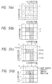
- the infrared intensity detecting unit 3 obtains an infrared intensity for each of the infrared ray sensing elements 7. Specifically, at predetermined period, the infrared intensity detecting unit 3 obtains an infrared intensity for each of the infrared ray sensing elements 7 as shown in Fig. 5(a), and supplies data of a distribution diagram of the obtained intensities (voltage distribution diagram) to the heat source position extracting unit 4.
- the heat source position extracting unit 4 which has received the data from the infrared intensity detecting unit 3 extracts infrared ray sensing elements 7 wherein the voltage exceeds a given threshold voltage, for example, 2.0 V in the case of Fig. 5(a).
- the heat source position extracting unit 4 conducts the binarization so as to set the extracted units 7 to be extracted pixels, and supplies data in which the infrared intensities of the extracted pixels 17 only are indicated as shown in Fig. 5(c), to the infrared center of gravity detecting unit 5.
- the heat source position extracting unit 4 first extracts infrared ray sensing elements 7 wherein the voltage exceeds the threshold voltage of 2.0 V from those shown in Fig. 5(a), and discriminates the extracted pixels 17 indicated by the hatched portion in Fig. 5(b), from the other infrared ray sensing elments 7. Therefore, the heat source position extracting unit 4 can determine that radiation light of a higher level enters the portions corresponding to the extracted pixels 17, and judge the heat source to have a shape indicated by the hatched portion in the figure.
- Data indicative of the infrared intensities and positions of the extracted pixels 17 are supplied to the infrared center of gravity detecting unit 5 so that the center of gravity of the infrared rays (center of gravity of the heat source) is detected by the infrared center of gravity detecting unit 5.
- the infrared center of gravity detecting unit 5 receives the data from the heat source position extracting unit 4, and obtains the X component x G and Y component y G of the center of gravity of the infrared rays on the basis of expressions, for example, (Ex. 1) and (Ex. 2) below which are previously given to the infrared center of gravity detecting unit 5.
- variable V i indicates the infrared intensity of an ith extracted pixel 17 in the case where an i number of pixels 17 are extracted by the heat source position extracting unit 4, and x i and y i are values of X- and Y-direction components of a distance (address) between a given reference position and the center of the respective extracted pixel 17.
- X-direction component x 1 of the address of the first extracted pixel 17a can be indicated as 1, and Y-direction component y 1 as 1.
- X-direction components x 2 , x 3 , and x 4 of the addresses of the second, third and fourth extracted pixel 17b, 17c, and 17d can be indicated as 2, 2, and 2, and Y-direction components y 2 , y 3 , and y 4 as 1, 2, and 3, respectively.
- the infrared center of gravity detecting unit 5 sequentially supplies the values of X and Y components x G and y G of the centers of gravity obtained from (Ex. 1) and (Ex. 2), to the heat source moving direction detecting unit 6.
- the heat source moving direction detecting unit 6 obtains the moving direction of the heat source from temporal vector displacement of the center of gravity of the infrared rays which is detected by the infrared center of gravity detecting unit 5. More specifically, the chopper 11 is moved so that a process is repeated in which radiation light from the heat source is alternatingly enabled and disabled at fixed time intervals to enter the infrared ray sensing elements 7 of the infrared sensor 1.
- the heat source moving direction detecting unit 6 obtains X- and Y-direction displacements of the center of gravity of the infrared rays for each frame, and further obtains an angle ⁇ of the moving direction of the center of gravity with respect to the reference axis of the center of gravity displacement vector, from a total sum ⁇ x Gsum of the X-direction displacements and a total sum ⁇ y Gsum of the Y-direction displacements.
- a total sum ⁇ x Gsum of X-direction displacements of the center of gravity of the heat source, and a total sum ⁇ y Gsum of Y-direction displacements can be obtained from the value of the displacement vector ( ⁇ x G(i) , ⁇ y G(i) ) of the center of gravity of the heat source which is obtained from (Ex. 3) and (Ex. 4), and operation expressions indicated by following (Ex. 5) and (Ex. 6):
- the infrared intensity detecting unit 3 detects the infrared intensity of each of the sensing elements 7, and supplies data indicative of the infrared intensity distribution such as those shown in Fig. 5(a), to the heat source position extracting unit 4.
- the heat source position extracting unit 4 which has received the data from the infrared intensity detecting unit 3 judges whether the infrared intensity of each of the sensing elements 7 exceeds the threshold voltage of 2.0 V or not.
- the heat source position extracting unit 4 extracts infrared ray sensing elements 7 wherein the voltage exceeds the threshold voltage as indicated by the hatched portion in Fig. 5(b), and then supplies data indicative of the infrared intensity distribution of the extracted pixels 17, to the infrared center of gravity detecting unit 5.
- the infrared center of gravity detecting unit 5 which has received the data from the heat source position extracting unit 4 obtains the X component x G and Y component y G of the infrared center of gravity from (Ex. 1) and (Ex. 2) above, and supplies the obtained data for each frame to the heat source moving direction detecting unit 6.
- x G and y G are obtained as follows, and the center of gravity of the heat source is located at a position G in Fig. 5(d).
- the heat source moving direction detecting unit 6 When data of the center of gravity of the heat source obtained by the infrared center of gravity detecting unit 5 are sequentially supplied to the heat source moving direction detecting unit 6, the heat source moving direction detecting unit 6 then obtains the angle of the moving direction of the heat source with respect to a reference axis (X-axis) from (Ex. 3) to (Ex. 7), on the basis of the data of the position of the heat source, in the following manner: It is assumed that the center of gravity of the heat source is moved in sequence from a point A 0 to a point A 3 in Fig. 6 and the extracted pixels 17 exist as indicated by the hatched portion in the figure.
- the center of gravity (x G1 , y G1 ) of the first frame counted after the detection of the heat source exists at the point A 0 , and therefore is indicated by (0.4, 1.8) in accordance with X and Y components of the address from the reference position S.
- the heat source position extracting unit 4 can determine an approximate position of the heat source and the shape of the heat source, and the infrared center of gravity detecting unit 5 can accurately detect the center of gravity of the heat source with high resolution.
- the heat source moving direction detecting unit 6 obtains the moving direction of the heat source. Even when a low-resolution infrared sensor array is used, therefore, the moving direction of the heat source can be determined with higher accuracy.
- the heat source detector of the embodiment uses the pyroelectric infrared sensor 1. Unlike a quantum infrared sensor, a pyroelectric infrared sensor is not necessary to be cooled to a very low temperature. Consequently, the size and cost of the heat source detector are prevented from being increased.
- the second embodiment is different from the fist embodiment in that the heat source moving direction detecting unit 6 calculates the moving direction of a heat source in a different method, and the other configuration and operation are the same as those of the first embodiment.
- the heat source moving direction detecting unit 6 of the second embodiment is so configured that the moving direction of a heat source is calculated as described below.
- the displacement vector ( ⁇ x G(i) , ⁇ y G(i) ) of the center of gravity of a heat source of an ith frame counted after the detection of the heat source is obtained from (Ex. 3) and (Ex. 4) described above.
- an angle ⁇ i which is formed by a displacement vector between adjacent frames and a reference axis (X-axis) is obtained from (Ex. 8).
- the center of gravity of each frame can accurately be detected, and the heat source moving direction detecting unit 6 can accurately obtain the angle ⁇ of the moving direction of the heat source with respect to the X-axis in the manner described above, thereby attaining the same effects as those of the first embodiment.
- the infrared sensor 1 in the embodiments is an array sensor in which four infrared ray sensing elements 7 are arranged both in vertical and lateral directions to form an array, for example, the number of the infrared ray sensing elements 7 is not restricted to the above, and the number of sensing devices in the vertical may be equal to or different from that in the lateral direction.
- adjacent infrared ray sensing elements 7 are not necessary to be made contact with each other, and may be disposed with leaving a gap therebetween as shown in Fig. 8. Even when the infrared ray sensing elements 7 are arranged with being spaced from each other, the center of gravity of a heat source and the moving direction of the heat source can accurately be detected as far as the infrared detector comprises an infrared analyzer 2 similar to those of the embodiments and operates in a similar manner. Even when the center of gravity of a heat source is in a gap formed between several infrared ray sensing elements 7 as shown in Fig. 8, furthermore, it is possible to accurately detect the position of the center of gravity and the moving direction of the heat source.
- the chopper 11 is disposed between the infrared lens 10 and the infrared sensor 1.
- the chopper 11 is not always necessary. If the infrared analyzer 2 is configured so as to, at regular time intervals, fetch signals indicative of the infrared intensities detected by the infrared ray sensing elements 7 of the infrared sensor 1, and analyze the signal, the chopper 11 may be omitted.
- the threshold voltage of the heat source position extracting unit 4 is previously set to be 2.0 V, and infrared ray sensing elements 7 wherein the voltage detected by the infrared intensity detecting unit 3 exceeds 2.0 V are extracted as the extracted pixels 17.
- the threshold voltage set to the heat source position extracting unit 4 is not limited to 2.0 V, and may have an adequate value.
- the way of obtaining the moving direction of a heat source by means of the heat source moving direction detecting unit 6 is not restricted to those of the embodiments as far as the heat source moving direction detecting unit 6 can obtain the moving direction of a heat source from temporal vector displacement of the center of gravity of infrared rays which is detected by the infrared center of gravity detecting unit.
- the embodiments comprise the heat source moving direction detecting unit 6 as an essential component.
- the heat source moving direction detecting unit 6 may be omitted, and the heat source detector of the invention may be configured so as to detect only the center of gravity of a heat source.
- the infrared intensity detecting unit of the infrared analyzer obtains the intensity of infrared rays for each of the infrared ray sensing devices which are arranged into an array form
- the infrared center of gravity detecting unit detects the center of gravity of a heat source which emits infrared rays, from the intensities of infrared rays which are obtained by the infrared intensity detecting unit. Therefore, analysis can finely be conducted on the basis of the data obtained for each of the infrared ray sensing devices, and the center of gravity of infrared rays (center of gravity of the heat source) can accurately be obtained.
- the moving direction of the heat source is obtained from accurate temporal vector displacement of the center of gravity of the heat source emitting infrared rays, the center being obtained by the infrared center of gravity detecting unit. Therefore, the moving direction of the heat source can accurately be obtained.
- the center of gravity of such a heat source emitting infrared rays, and the moving direction of the heat source can be detected without using a quantum infrared sensor. Therefore, elements of an infrared sensor are not necessary to be cooled to a very low temperature in order to operate the infrared sensor, whereby the size and cost of the detector are prevented from being increased. Even when an infrared sensor having a resolution level which is not so high is used in the heat source detector, infrared rays can be analyzed with high resolution, and hence the center of gravity of a heat source and the moving direction of the heat source can accurately be detected.
Landscapes
- Physics & Mathematics (AREA)
- Electromagnetism (AREA)
- Engineering & Computer Science (AREA)
- General Physics & Mathematics (AREA)
- Radar, Positioning & Navigation (AREA)
- Remote Sensing (AREA)
- Photometry And Measurement Of Optical Pulse Characteristics (AREA)
- Geophysics And Detection Of Objects (AREA)
Claims (4)
- Ein Wärmequellendetektor mit folgenden Merkmalen:einem pyroelektrischen Infrarotsensor (1) mit einer Mehrzahl von Infrarotstrahlerfassungselementen (7); undeinem Infrarotanalysator (2) zum Analysieren eines Erfassungssignals, das durch die Infrarotstrahlerfassungselemente (7) während einer Mehrzahl von Erfassungsintervallen (N) erfaßt wird, wobei der Infrarotanalysator folgende Merkmale aufweist:eine Infrarotintensitätserfassungseinrichtung (3) zum Erfassen einer Infrarotintensität für jedes der Infrarotstrahlerfassungselemente (7) während jedes Erfassungsintervalls;eine Wärmequellenpositionsextrahiereinrichtung (4), die während jedes Erfassungsintervalls die Infrarotintensität für jedes der Infrarotstrahlerfassungselemente (7) von der Infrarotintensitätserfassungseinrichtung (3) empfängt, und die Infrarotstrahlerfassungselemente (7) extrahiert, die einen vorbestimmten Intensitätspegel oder einen größeren als den vorbestimmten Intensitätspegel aufweisen;eine Infrarotschwerpunktserfassungseinrichtung (5) zum Erfassen des Schwerpunkts einer Wärmequelle, die Infrarotstrahlen emittiert, auf der Basis der Infrarotintensitäten der Infrarotstrahlerfassungselemente (7), die durch die Wärmequellenpositionsextrahiereinrichtung (4) extrahiert werden, während jedes Erfassungsintervalls; undeine Wärmequellenbewegungsrichtungserfassungseinrichtung (6) zum Erfassen einer Bewegungsrichtung der Wärmequelle mit einer Auflösung, die höher ist als die Auflösung des Infrarotsensors (1), wobei die Wärmequellenbewegungsrichtungserfassungseinrichtung (6) eine Einrichtung zum Halten des Schwerpunkts einer Mehrzahl von Erfassungsintervallen, eine Einrichtung zum Erfassen einer relativen Verschiebung des Schwerpunkts bei aufeinanderfolgenden Erfassungsintervallen und eine Einrichtung zum Bestimmen der Bewegungsrichtung der Wärmequelle auf der Basis der relativen Verschiebung des Schwerpunkts aufweist.
- Ein Wärmequellendetektor gemäß Anspruch 1, bei dem die Mehrzahl von Infrarotstrahlerfassungselementen (7) in einer Arrayform in der X- und der Y-Richtung angeordnet ist.
- Ein Wärmequellendetektor gemäß Anspruch 1, der ferner einen Zerhacker (11) aufweist, der vor dem Infrarotsensor (1) vorgesehen ist, wobei der Zerhacker (11) verschiebbar bewegbar ist, um es entweder den Infrarotstrahlen zu ermöglichen, in die Infraroterfassungselemente (7) ohne Behinderung einzutreten, oder um es zu verhindern, daß die Infrarotstrahlen in die Infraroterfassungselemente (7) eintreten.
- Ein Wärmequellendetektor gemäß Anspruch 1, bei dem der Infrarotanalysator (2) die Infrarotintensität für jedes der Infrarotstrahlerfassungselementen (7) zu regelmäßigen Zeitintervallen empfängt.
Applications Claiming Priority (3)
| Application Number | Priority Date | Filing Date | Title |
|---|---|---|---|
| JP339410/93 | 1993-12-03 | ||
| JP33941093A JPH07159236A (ja) | 1993-12-03 | 1993-12-03 | 熱源検知装置 |
| JP33941093 | 1993-12-03 |
Publications (3)
| Publication Number | Publication Date |
|---|---|
| EP0656532A2 EP0656532A2 (de) | 1995-06-07 |
| EP0656532A3 EP0656532A3 (de) | 1996-03-20 |
| EP0656532B1 true EP0656532B1 (de) | 1999-10-27 |
Family
ID=18327213
Family Applications (1)
| Application Number | Title | Priority Date | Filing Date |
|---|---|---|---|
| EP94118882A Expired - Lifetime EP0656532B1 (de) | 1993-12-03 | 1994-11-30 | Wärmequellendetektor |
Country Status (4)
| Country | Link |
|---|---|
| US (1) | US5565683A (de) |
| EP (1) | EP0656532B1 (de) |
| JP (1) | JPH07159236A (de) |
| DE (1) | DE69421365T2 (de) |
Cited By (1)
| Publication number | Priority date | Publication date | Assignee | Title |
|---|---|---|---|---|
| WO2019210520A1 (zh) * | 2018-05-04 | 2019-11-07 | 深圳钶钽智能技术有限公司 | 一种空间分区探测装置、系统及方法 |
Families Citing this family (13)
| Publication number | Priority date | Publication date | Assignee | Title |
|---|---|---|---|---|
| GB2353856B (en) * | 1999-08-27 | 2001-10-24 | Infrared Integrated Syst Ltd | Improvements in position determination using arrays of radiation detectors |
| US6872945B2 (en) | 2002-11-08 | 2005-03-29 | General Electric Company | Apparatus and method for detection of railroad wheel and bearing temperature |
| GR1004455B (el) * | 2003-02-21 | 2004-02-17 | Δουκασαχριστοσα | Ανιχνευτησαπηγωναθερμοτητος |
| JP5595828B2 (ja) * | 2010-08-09 | 2014-09-24 | 日本セラミック株式会社 | 赤外線人体検出装置 |
| WO2013077403A1 (ja) * | 2011-11-23 | 2013-05-30 | 国立大学法人神戸大学 | 動作検出装置 |
| US20140045463A1 (en) * | 2012-08-10 | 2014-02-13 | Silverplus, Inc. | Wearable Communication Device |
| US9347834B2 (en) * | 2013-11-04 | 2016-05-24 | Redwood Systems, Inc. | Infrared sensor array based temperature monitoring systems for data centers and related methods |
| CN104008623A (zh) * | 2014-05-04 | 2014-08-27 | 福建创高安防技术股份有限公司 | 一种红外入侵探测方法及其装置 |
| WO2016170973A1 (ja) * | 2015-04-20 | 2016-10-27 | シャープ株式会社 | 集積回路、及び測定装置 |
| US10006983B2 (en) * | 2015-10-21 | 2018-06-26 | Everspring Industry Co., Ltd. | Apparatus and method for detecting azimuthal angle of heat source |
| JP6786264B2 (ja) | 2016-05-27 | 2020-11-18 | 株式会社東芝 | 情報処理装置、情報処理方法、および車両 |
| EP3762909A1 (de) * | 2018-05-28 | 2021-01-13 | Greenwave Systems PTE. LTD. | Bereichsüberwachung und kommunikation |
| CN114067546B (zh) * | 2020-07-29 | 2023-04-18 | 深圳绿米联创科技有限公司 | 位置检测方法、装置及电子设备 |
Family Cites Families (12)
| Publication number | Priority date | Publication date | Assignee | Title |
|---|---|---|---|---|
| US4064533A (en) * | 1975-10-24 | 1977-12-20 | Westinghouse Electric Corporation | CCD focal plane processor for moving target imaging |
| US4539590A (en) * | 1983-03-08 | 1985-09-03 | Gage Richard J | Method and apparatus for processing optical tracking signals |
| EP0159840B1 (de) * | 1984-04-14 | 1990-11-07 | British Aerospace Public Limited Company | Strahlungsdetektoranordnung |
| DE3618736A1 (de) * | 1986-06-04 | 1987-12-10 | Schmermund Maschf Alfred | Verfahren und vorrichtung zum einhuellen von zigarettenpaeckchen in klarsichtfolie |
| JPS63155975A (ja) * | 1986-12-19 | 1988-06-29 | Matsushita Electric Ind Co Ltd | 焦電型カメラ装置 |
| US4855932A (en) * | 1987-07-08 | 1989-08-08 | Lockheed Electronics Company | Three-dimensional electro-optical tracker |
| DE3729059A1 (de) * | 1987-08-31 | 1989-03-09 | Menke Josef F | Verfahren zur zielfeldaufklaerung |
| JP2552728B2 (ja) * | 1989-05-31 | 1996-11-13 | 富士通株式会社 | 赤外線監視システム |
| JPH0341305A (ja) * | 1989-07-07 | 1991-02-21 | Matsushita Electric Ind Co Ltd | 焦電型赤外線検知装置 |
| FR2665600A1 (fr) * | 1990-08-03 | 1992-02-07 | Thomson Csf | Procede de detection pour camera panoramique, camera pour sa mise en óoeuvre, et systeme de veille equipe d'une telle camera. |
| FR2672989A1 (fr) * | 1991-02-15 | 1992-08-21 | Sodern | Dispositif de determination de la direction d'une source emissive de faible luminosite et son application a la visee stellaire. |
| US5283551A (en) * | 1991-12-31 | 1994-02-01 | Aritech Corporation | Intrusion alarm system |
-
1993
- 1993-12-03 JP JP33941093A patent/JPH07159236A/ja active Pending
-
1994
- 1994-11-30 EP EP94118882A patent/EP0656532B1/de not_active Expired - Lifetime
- 1994-11-30 DE DE69421365T patent/DE69421365T2/de not_active Expired - Fee Related
- 1994-12-05 US US08/349,721 patent/US5565683A/en not_active Expired - Lifetime
Cited By (1)
| Publication number | Priority date | Publication date | Assignee | Title |
|---|---|---|---|---|
| WO2019210520A1 (zh) * | 2018-05-04 | 2019-11-07 | 深圳钶钽智能技术有限公司 | 一种空间分区探测装置、系统及方法 |
Also Published As
| Publication number | Publication date |
|---|---|
| JPH07159236A (ja) | 1995-06-23 |
| DE69421365D1 (de) | 1999-12-02 |
| EP0656532A2 (de) | 1995-06-07 |
| EP0656532A3 (de) | 1996-03-20 |
| US5565683A (en) | 1996-10-15 |
| DE69421365T2 (de) | 2000-06-08 |
Similar Documents
| Publication | Publication Date | Title |
|---|---|---|
| EP0656532B1 (de) | Wärmequellendetektor | |
| US7154531B2 (en) | Detecting objects by digital imaging device | |
| US6137407A (en) | Humanoid detector and method that senses infrared radiation and subject size | |
| CN105473393B (zh) | 用于检测车辆上操控姿态的传感器机构 | |
| US7834305B2 (en) | Image processing device | |
| US5313060A (en) | Multi-sensor doubled row direction sensitive counting and switching device | |
| US6476859B1 (en) | Thermal tracker | |
| KR101999993B1 (ko) | 레이더 및 카메라를 이용한 무인 단속시스템 | |
| CN106600777A (zh) | 基于红外阵列人数传感器的计数方法及装置 | |
| DE19628049C2 (de) | Vorrichtung zur Erfassung der Position eines menschlichen Körpers unter Verwendung eines Infrarotstrahlsensors | |
| EP0928465B1 (de) | Erfassungssystem | |
| US20090219388A1 (en) | Method and system for detecting an individual by means of passive infrared sensors | |
| US7645990B2 (en) | Thermal-type infrared imaging device and operation method thereof | |
| JPH07296155A (ja) | 車両の通行をモニタする方法およびシステム | |
| US20040169131A1 (en) | Intrusion detection system | |
| US20200128188A1 (en) | Image pickup device and image pickup system | |
| DE3614277A1 (de) | Abtastfeuerueberwachungssystem | |
| EP1079349A2 (de) | Detektierung der Position und der Bewegung von Subpixelbildern | |
| JP3806789B2 (ja) | 物体検出装置 | |
| JP2523948B2 (ja) | 焦電型赤外線検知装置 | |
| WO2023153219A1 (ja) | 光学素子、及び、光学装置 | |
| US7795569B2 (en) | Focal plane detector with integral processor for object edge determination | |
| JPH02140628A (ja) | 赤外線撮像装置 | |
| JP2766708B2 (ja) | サーモグラフィ装置 | |
| JPH1011621A (ja) | 自動改札機用人間検知装置 |
Legal Events
| Date | Code | Title | Description |
|---|---|---|---|
| PUAI | Public reference made under article 153(3) epc to a published international application that has entered the european phase |
Free format text: ORIGINAL CODE: 0009012 |
|
| AK | Designated contracting states |
Kind code of ref document: A2 Designated state(s): DE FR GB IT |
|
| PUAL | Search report despatched |
Free format text: ORIGINAL CODE: 0009013 |
|
| AK | Designated contracting states |
Kind code of ref document: A3 Designated state(s): DE FR GB IT |
|
| 17P | Request for examination filed |
Effective date: 19960611 |
|
| 17Q | First examination report despatched |
Effective date: 19970605 |
|
| GRAG | Despatch of communication of intention to grant |
Free format text: ORIGINAL CODE: EPIDOS AGRA |
|
| GRAG | Despatch of communication of intention to grant |
Free format text: ORIGINAL CODE: EPIDOS AGRA |
|
| GRAH | Despatch of communication of intention to grant a patent |
Free format text: ORIGINAL CODE: EPIDOS IGRA |
|
| GRAH | Despatch of communication of intention to grant a patent |
Free format text: ORIGINAL CODE: EPIDOS IGRA |
|
| GRAA | (expected) grant |
Free format text: ORIGINAL CODE: 0009210 |
|
| ITF | It: translation for a ep patent filed |
Owner name: SOCIETA' ITALIANA BREVETTI S.P.A. |
|
| AK | Designated contracting states |
Kind code of ref document: B1 Designated state(s): DE FR GB IT |
|
| REF | Corresponds to: |
Ref document number: 69421365 Country of ref document: DE Date of ref document: 19991202 |
|
| ET | Fr: translation filed | ||
| PLBE | No opposition filed within time limit |
Free format text: ORIGINAL CODE: 0009261 |
|
| STAA | Information on the status of an ep patent application or granted ep patent |
Free format text: STATUS: NO OPPOSITION FILED WITHIN TIME LIMIT |
|
| 26N | No opposition filed | ||
| REG | Reference to a national code |
Ref country code: GB Ref legal event code: IF02 |
|
| PGFP | Annual fee paid to national office [announced via postgrant information from national office to epo] |
Ref country code: DE Payment date: 20071122 Year of fee payment: 14 |
|
| PGFP | Annual fee paid to national office [announced via postgrant information from national office to epo] |
Ref country code: IT Payment date: 20071127 Year of fee payment: 14 |
|
| PGFP | Annual fee paid to national office [announced via postgrant information from national office to epo] |
Ref country code: GB Payment date: 20071128 Year of fee payment: 14 Ref country code: FR Payment date: 20071108 Year of fee payment: 14 |
|
| GBPC | Gb: european patent ceased through non-payment of renewal fee |
Effective date: 20081130 |
|
| PG25 | Lapsed in a contracting state [announced via postgrant information from national office to epo] |
Ref country code: IT Free format text: LAPSE BECAUSE OF NON-PAYMENT OF DUE FEES Effective date: 20081130 |
|
| REG | Reference to a national code |
Ref country code: FR Ref legal event code: ST Effective date: 20090731 |
|
| PG25 | Lapsed in a contracting state [announced via postgrant information from national office to epo] |
Ref country code: DE Free format text: LAPSE BECAUSE OF NON-PAYMENT OF DUE FEES Effective date: 20090603 |
|
| PG25 | Lapsed in a contracting state [announced via postgrant information from national office to epo] |
Ref country code: GB Free format text: LAPSE BECAUSE OF NON-PAYMENT OF DUE FEES Effective date: 20081130 |
|
| PG25 | Lapsed in a contracting state [announced via postgrant information from national office to epo] |
Ref country code: FR Free format text: LAPSE BECAUSE OF NON-PAYMENT OF DUE FEES Effective date: 20081130 |