EP0656249B1 - Modulares Unterbau für Fliesenschneidvorrichtungen - Google Patents
Modulares Unterbau für Fliesenschneidvorrichtungen Download PDFInfo
- Publication number
- EP0656249B1 EP0656249B1 EP94113434A EP94113434A EP0656249B1 EP 0656249 B1 EP0656249 B1 EP 0656249B1 EP 94113434 A EP94113434 A EP 94113434A EP 94113434 A EP94113434 A EP 94113434A EP 0656249 B1 EP0656249 B1 EP 0656249B1
- Authority
- EP
- European Patent Office
- Prior art keywords
- base
- base according
- coupling
- interlocking
- modular
- Prior art date
- Legal status (The legal status is an assumption and is not a legal conclusion. Google has not performed a legal analysis and makes no representation as to the accuracy of the status listed.)
- Expired - Lifetime
Links
- 230000008878 coupling Effects 0.000 claims abstract description 7
- 238000010168 coupling process Methods 0.000 claims abstract description 7
- 238000005859 coupling reaction Methods 0.000 claims abstract description 7
- 230000006835 compression Effects 0.000 claims description 2
- 238000007906 compression Methods 0.000 claims description 2
- 238000001125 extrusion Methods 0.000 claims description 2
- 230000000284 resting effect Effects 0.000 claims 1
- 239000000463 material Substances 0.000 description 6
- 238000005520 cutting process Methods 0.000 description 2
- 239000004033 plastic Substances 0.000 description 2
- 229920003023 plastic Polymers 0.000 description 2
- 238000003825 pressing Methods 0.000 description 2
- 229910000838 Al alloy Inorganic materials 0.000 description 1
- 238000005266 casting Methods 0.000 description 1
- 230000000670 limiting effect Effects 0.000 description 1
- 238000004519 manufacturing process Methods 0.000 description 1
- 239000007769 metal material Substances 0.000 description 1
- 230000004048 modification Effects 0.000 description 1
- 238000012986 modification Methods 0.000 description 1
- 238000000465 moulding Methods 0.000 description 1
- 125000006850 spacer group Chemical group 0.000 description 1
Images

Classifications
-
- B—PERFORMING OPERATIONS; TRANSPORTING
- B28—WORKING CEMENT, CLAY, OR STONE
- B28D—WORKING STONE OR STONE-LIKE MATERIALS
- B28D1/00—Working stone or stone-like materials, e.g. brick, concrete or glass, not provided for elsewhere; Machines, devices, tools therefor
- B28D1/22—Working stone or stone-like materials, e.g. brick, concrete or glass, not provided for elsewhere; Machines, devices, tools therefor by cutting, e.g. incising
- B28D1/225—Working stone or stone-like materials, e.g. brick, concrete or glass, not provided for elsewhere; Machines, devices, tools therefor by cutting, e.g. incising for scoring or breaking, e.g. tiles
Definitions
- the present invention relates to a modular base for tile cutters.
- Bases for tile cutters are constituted by an elongated platform to which an upper median rib is longitudinally rigidly coupled: two posts are fixed to the ends of said rib and support a rail along which a slider is movably mounted; a wheel for cutting into the surface of the tile and a shoe for breaking the tile by pressing it (simultaneously on the two sides of the cutting line cut previously with the wheel) against the rib of the base are installed on said slider.
- EP-A-0 428 070 discloses a modular base as defined in the preamble of independent claim 1.
- the principal aim of the present invention is to obviate the above drawbacks of known devices; in other words, to provide a modular base for tile cutters which is extremely light and strong and does not entail the manufacture of a mold for each size.
- an object of the present invention is to achieve the above aim with a structure that is simple, relatively easy to execute in practice, safe in use, effective in operation and relatively cheap.
- the present invention provides a modular base for tile cutters, which is characterized in that it comprises an extruded hollow profiled element which is longitudinally provided with a median rib on one of its faces and has, along its lateral edges, interlocking joints for the coupling of optional lateral extensions.
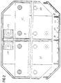
- the reference numeral 1 generally designates a modular base for tile cutters according to the invention.
- the base 1 is constituted by an extruded hollow profiled element 2 made of a material such as aluminum alloys, in which there are an upper thick portion 3a and a lower thick portion 3b which are mutually joined by thin spacers 4, 5 and by stiffening elements 6, 7a, 7b.
- the profiled element is longitudinally provided with a median contrast rib 8 on its upper face and has, along the lateral edges of the stiffening elements 7, respective interlocking joints 9 for coupling optional lateral extensions 10: the rib 8 is longitudinally crossed by a triangular cavity 8a.
- the interlocking joints 9 are of the dovetail type, advantageously of the mortise kind.
- the profiled element 2 has longitudinal supporting ribs 11 at its center and sides in a downward region.
- the extensions 10 are also constituted by an upper thick portion 12a and by a lower thick portion 12b which are joined at their sides by stiffening elements 13 and 14; the stiffening element 13 has a longitudinal supporting rib 15 in a downward region, whereas the stiffening element 14 forms, on one side, a longitudinal dovetail tenon 16 suitable to couple to one of the interlocking joints 9: conveniently, the ends of the extensions are cut at 45 degrees so that the base, as a whole, is shaped like an elongated rectangle with rounded corners.
- closure elements 17 which can be fixed in a snap-together manner and are made of plastic material:
- the closure elements 17 have an elongated rod 18 which is centrally provided with a contoured ridge 19 suitable to rest against the rib 8 (the ridge 19 is centrally provided with a tooth that can interlock in the cavity 8a);
- the rod 18 has, at its sides, two extensions 20 which are inclined at 45 degrees and suitable to rest against the ends of the extensions 10, which are cut at 45 degrees.
- the rod 18 and the two extensions 20 have multiple pairs of lugs 21 which are suitable to fit against the upper and lower thick portions of the profiled element 2 and of the extensions.
- Two supports 24 are mounted at the two ends of the rib 8 and are manufactured by molding a material such as plastics for the rail along which the slider slides: the supports 24 comprise a footing 25 below which there is a fork 26 that lies astride the rib 8 and two shoes 27a, 27b which are crossed by respective holes 28 for screws for fixing to the profiled element 2: in an upward region, the supports 24 form the two arms 29 of a fork with holes 30 for screws for fixing the rail of the slider.
- At least two lateral secondary surfaces 31 are mounted above the base and are covered, in an upward region, by an optional mat 32 made of a material such as rubber: the secondary surfaces are rectangular, are arranged on either side of the rib 8, and have seats 33 for the heads 34 of modular feet 35 for connection to the base: the feet 35 are made of two parts, one of which is a lower stub 36 the expanded head 37 whereof is suitable to pass through a wide hole in the lower thick portion 3b and rest against the edges of a corresponding narrow hole 38 of the upper thick portion 3a: the other part of the feet is constituted by a pin 39 which has a head 34 and is crossed by a central seat 40 for a screw and is provided, in a downward region, with a portion which is cut into sectors, is shaped like a truncated cone, and is suitable to expand when the screw penetrates and to fix itself to the stub 36; in order to prevent rotation of the pin during the tightening of the screw, at the top of the stub there are two radial notches
- the rib 8 In order to vary the level of the top of the rib 8 it is possible to provide the rib 8 so that it can be removed, with an interlocking joint, for example of the dovetail type, at its base in order to couple to a corresponding longitudinal dovetail slot of the profiled element 2.
Landscapes
- Engineering & Computer Science (AREA)
- Mining & Mineral Resources (AREA)
- Mechanical Engineering (AREA)
- Press-Shaping Or Shaping Using Conveyers (AREA)
- Processing Of Stones Or Stones Resemblance Materials (AREA)
- Floor Finish (AREA)
- Perforating, Stamping-Out Or Severing By Means Other Than Cutting (AREA)
Claims (8)
- Modularer Unterbau für Fliesenschneidvorrichtungen, der ein extrudiertes, hohles, profiliertes Element (2) aufweist, welches in Längsrichtung mit einer mittigen Rippe (8) auf einer seiner Seiten versehen ist und welcher entlang seiner seitlichen Ränder Verbindungsmittel zum Ankuppeln seitlicher Verlängerungen (10) aufweist,
dadurch gekennzeichnet,
daß die genannten Verbindungsmittel Verriegelungselemente (9) zum Ankoppeln von optionalen seitlichen Verlängerungen (10) aufweist, wobei sich die genannten Verriegelungselemente (9) über die gesamte Länge der seitlichen Ränder der modularen Basis erstrecken. - Basis nach Anspruch 1,
dadurch gekennzeichnet,
daß die Verriegelungselemente (9) schwalbenschwanzartig sind. - Basis nach Anspruch 2,
dadurch gekennzeichnet,
daß die genannten Verriegelungselemente (9) nutenartig ausgebildet sind. - Basis nach Anspruch 1,
dadurch gekennzeichnet,
daß das profilierte Element (2) in seinem unteren Bereich Rippen (11) in seinem Zentrum und an den Seiten aufweist. - Basis nach Anspruch 1,
dadurch gekennzeichnet,
daß die Enden der genannten profilierten Elemente von entsprechenden, einschnappbaren Verschlußelementen (17) geschlossen werden, die fest an den profilierten Elementen mittels Schrauben gekoppelt werden können, die in entsprechende Sitze (23) einkoppeln, die bei der Extrusion gebildet wurden. - Basis nach Anspruch 1,
dadurch gekennzeichnet,
daß wenigstens zwei seitliche schwingende Senkundäroberflächen (31) in der oberen Region der genannten Basis montiert sind, wobei die sekundären Oberflächen mit modularen Füßen (35) ausgerüstet sind zur Verbindung mit der genannten Basis, wobei spiralförmige Druckfedern auf den Füßen zentriert sind. - Basis nach Anspruch 1,
dadurch gekennzeichnet,
daß die mittige Rippe (8) abnehmbar ist und in ihrer nach unten weisenden Region eine Verriegelungskupplung für einen entsprechenden Längsschlitz im genannten profilierten Element (2) aufweist. - Basis nach Anspruch 7,
dadurch gekennzeichnet,
daß die Verriegelungskupplung der mittleren Rippe schwalbenschwanzartig ausgebildet ist.
Applications Claiming Priority (2)
| Application Number | Priority Date | Filing Date | Title |
|---|---|---|---|
| IT93BO000386A IT1264224B1 (it) | 1993-09-23 | 1993-09-23 | Basamento modulare per tagliapiastrelle |
| ITBO930386 | 1993-09-23 |
Publications (2)
| Publication Number | Publication Date |
|---|---|
| EP0656249A1 EP0656249A1 (de) | 1995-06-07 |
| EP0656249B1 true EP0656249B1 (de) | 2000-11-15 |
Family
ID=11339243
Family Applications (1)
| Application Number | Title | Priority Date | Filing Date |
|---|---|---|---|
| EP94113434A Expired - Lifetime EP0656249B1 (de) | 1993-09-23 | 1994-08-29 | Modulares Unterbau für Fliesenschneidvorrichtungen |
Country Status (5)
| Country | Link |
|---|---|
| EP (1) | EP0656249B1 (de) |
| AT (1) | ATE197568T1 (de) |
| DE (1) | DE69426286T2 (de) |
| ES (1) | ES2151915T3 (de) |
| IT (1) | IT1264224B1 (de) |
Families Citing this family (3)
| Publication number | Priority date | Publication date | Assignee | Title |
|---|---|---|---|---|
| NL1033776C2 (nl) * | 2007-04-27 | 2008-10-28 | Robo Beheer B V | Ultra stijve handbediende tegelsnijder. |
| ES2545036B1 (es) | 2014-02-07 | 2016-06-14 | Bellota Herramientas, S.A. | Máquina modular para cortar piezas cerámicas |
| DE102014102965A1 (de) | 2014-03-06 | 2015-09-10 | Wolfcraft Gmbh | Fliesenschneider mit einem einen Basisholm aufweisenden Auflagegestell |
Family Cites Families (3)
| Publication number | Priority date | Publication date | Assignee | Title |
|---|---|---|---|---|
| GB1481135A (en) * | 1975-05-20 | 1977-07-27 | Brandon Enterprises Ltd | Tile cutters |
| ES2040021T3 (es) * | 1989-11-12 | 1993-10-01 | Kaufmann Gesellschaft M.B.H. & Co.Kg | Dispositivo para cortar baldosas y plaquetas. |
| IT1253014B (it) * | 1991-09-09 | 1995-07-10 | Skc Di Tondini Claudio | Tagliapiastrelle a rotella |
-
1993
- 1993-09-23 IT IT93BO000386A patent/IT1264224B1/it active IP Right Grant
-
1994
- 1994-08-29 AT AT94113434T patent/ATE197568T1/de not_active IP Right Cessation
- 1994-08-29 EP EP94113434A patent/EP0656249B1/de not_active Expired - Lifetime
- 1994-08-29 DE DE69426286T patent/DE69426286T2/de not_active Expired - Fee Related
- 1994-08-29 ES ES94113434T patent/ES2151915T3/es not_active Expired - Lifetime
Also Published As
| Publication number | Publication date |
|---|---|
| ITBO930386A1 (it) | 1995-03-23 |
| DE69426286D1 (de) | 2000-12-21 |
| ITBO930386A0 (it) | 1993-09-23 |
| IT1264224B1 (it) | 1996-09-23 |
| ATE197568T1 (de) | 2000-12-15 |
| ES2151915T3 (es) | 2001-01-16 |
| EP0656249A1 (de) | 1995-06-07 |
| DE69426286T2 (de) | 2001-04-12 |
Similar Documents
| Publication | Publication Date | Title |
|---|---|---|
| EP0437375B1 (de) | Verfahren und Vorrichtung zur Herstellung einer Mauer aus Glasblocksteinen | |
| US10890001B2 (en) | Formwork panel for concrete-work shutterings | |
| US5761867A (en) | Tile support insert | |
| US6076807A (en) | Fence or deck post cap | |
| US3212786A (en) | Skate with plastic frame | |
| US5706625A (en) | Supportless dasher board | |
| US6513826B1 (en) | Device for connecting a snow glider to the boot of a person using a snow glider | |
| EP0656249B1 (de) | Modulares Unterbau für Fliesenschneidvorrichtungen | |
| EP1426526B1 (de) | Schalung | |
| ES2181146T3 (es) | Traviesa de ferrocarril que comprende una zapata, y zapata para dicha traviesa. | |
| CA2170943C (en) | Supportless dasher board | |
| KR102336798B1 (ko) | 에어컨 실외기용 시멘트블록 받침대 제조장치 | |
| US4451032A (en) | Plastic ski slide | |
| JP3230107B2 (ja) | 建築型枠用の合成樹脂製単位枠 | |
| US1079045A (en) | False work for concrete constructions. | |
| KR101879452B1 (ko) | 서포트 거푸집의 틈새 보강 구조체 | |
| AU2008100492A4 (en) | Mounting panel | |
| JP2002235426A (ja) | 簀の子形の床マット | |
| JPS5922832Y2 (ja) | 階段 | |
| KR100530343B1 (ko) | 계단용 디딤블록의 제조형틀 | |
| JPS6118981Y2 (de) | ||
| KR102169180B1 (ko) | 도로경계석 받침대 | |
| US954645A (en) | Mold. | |
| JP2000317926A (ja) | コンクリートスラブ等の製造用型枠 | |
| JPH08112459A (ja) | スターティングブロック |
Legal Events
| Date | Code | Title | Description |
|---|---|---|---|
| PUAI | Public reference made under article 153(3) epc to a published international application that has entered the european phase |
Free format text: ORIGINAL CODE: 0009012 |
|
| AK | Designated contracting states |
Kind code of ref document: A1 Designated state(s): AT DE ES FR |
|
| 17P | Request for examination filed |
Effective date: 19951129 |
|
| 17Q | First examination report despatched |
Effective date: 19980717 |
|
| GRAG | Despatch of communication of intention to grant |
Free format text: ORIGINAL CODE: EPIDOS AGRA |
|
| GRAG | Despatch of communication of intention to grant |
Free format text: ORIGINAL CODE: EPIDOS AGRA |
|
| 17Q | First examination report despatched |
Effective date: 19980717 |
|
| GRAG | Despatch of communication of intention to grant |
Free format text: ORIGINAL CODE: EPIDOS AGRA |
|
| GRAH | Despatch of communication of intention to grant a patent |
Free format text: ORIGINAL CODE: EPIDOS IGRA |
|
| GRAH | Despatch of communication of intention to grant a patent |
Free format text: ORIGINAL CODE: EPIDOS IGRA |
|
| GRAA | (expected) grant |
Free format text: ORIGINAL CODE: 0009210 |
|
| AK | Designated contracting states |
Kind code of ref document: B1 Designated state(s): AT DE ES FR |
|
| REF | Corresponds to: |
Ref document number: 197568 Country of ref document: AT Date of ref document: 20001215 Kind code of ref document: T |
|
| REF | Corresponds to: |
Ref document number: 69426286 Country of ref document: DE Date of ref document: 20001221 |
|
| ET | Fr: translation filed | ||
| REG | Reference to a national code |
Ref country code: ES Ref legal event code: FG2A Ref document number: 2151915 Country of ref document: ES Kind code of ref document: T3 |
|
| PLBE | No opposition filed within time limit |
Free format text: ORIGINAL CODE: 0009261 |
|
| STAA | Information on the status of an ep patent application or granted ep patent |
Free format text: STATUS: NO OPPOSITION FILED WITHIN TIME LIMIT |
|
| 26N | No opposition filed | ||
| PGFP | Annual fee paid to national office [announced via postgrant information from national office to epo] |
Ref country code: FR Payment date: 20020724 Year of fee payment: 9 |
|
| PGFP | Annual fee paid to national office [announced via postgrant information from national office to epo] |
Ref country code: DE Payment date: 20020802 Year of fee payment: 9 |
|
| PGFP | Annual fee paid to national office [announced via postgrant information from national office to epo] |
Ref country code: ES Payment date: 20020821 Year of fee payment: 9 |
|
| PGFP | Annual fee paid to national office [announced via postgrant information from national office to epo] |
Ref country code: AT Payment date: 20020826 Year of fee payment: 9 |
|
| PG25 | Lapsed in a contracting state [announced via postgrant information from national office to epo] |
Ref country code: AT Free format text: LAPSE BECAUSE OF NON-PAYMENT OF DUE FEES Effective date: 20030829 |
|
| PG25 | Lapsed in a contracting state [announced via postgrant information from national office to epo] |
Ref country code: ES Free format text: LAPSE BECAUSE OF NON-PAYMENT OF DUE FEES Effective date: 20030830 |
|
| PG25 | Lapsed in a contracting state [announced via postgrant information from national office to epo] |
Ref country code: DE Free format text: LAPSE BECAUSE OF NON-PAYMENT OF DUE FEES Effective date: 20040302 |
|
| PG25 | Lapsed in a contracting state [announced via postgrant information from national office to epo] |
Ref country code: FR Free format text: LAPSE BECAUSE OF NON-PAYMENT OF DUE FEES Effective date: 20040430 |
|
| REG | Reference to a national code |
Ref country code: FR Ref legal event code: ST |
|
| REG | Reference to a national code |
Ref country code: ES Ref legal event code: FD2A Effective date: 20030830 |