EP0655383A1 - Energieaufnehmende Einrichtung für die Lenksäule eines Kraftfahrzeugs - Google Patents
Energieaufnehmende Einrichtung für die Lenksäule eines Kraftfahrzeugs Download PDFInfo
- Publication number
- EP0655383A1 EP0655383A1 EP94402541A EP94402541A EP0655383A1 EP 0655383 A1 EP0655383 A1 EP 0655383A1 EP 94402541 A EP94402541 A EP 94402541A EP 94402541 A EP94402541 A EP 94402541A EP 0655383 A1 EP0655383 A1 EP 0655383A1
- Authority
- EP
- European Patent Office
- Prior art keywords
- support
- axis
- tube
- energy absorption
- absorption device
- Prior art date
- Legal status (The legal status is an assumption and is not a legal conclusion. Google has not performed a legal analysis and makes no representation as to the accuracy of the status listed.)
- Granted
Links
- 230000002787 reinforcement Effects 0.000 claims description 69
- 238000010521 absorption reaction Methods 0.000 claims description 34
- 230000000903 blocking effect Effects 0.000 claims description 25
- 125000006850 spacer group Chemical group 0.000 claims description 4
- 238000003466 welding Methods 0.000 claims description 4
- 238000002788 crimping Methods 0.000 claims description 3
- 239000004020 conductor Substances 0.000 claims description 2
- 208000031968 Cadaver Diseases 0.000 description 18
- 239000006096 absorbing agent Substances 0.000 description 3
- 241000287107 Passer Species 0.000 description 1
- 229910000831 Steel Inorganic materials 0.000 description 1
- 239000011324 bead Substances 0.000 description 1
- 238000006073 displacement reaction Methods 0.000 description 1
- 239000000463 material Substances 0.000 description 1
- 230000000750 progressive effect Effects 0.000 description 1
- 230000000717 retained effect Effects 0.000 description 1
- 239000010959 steel Substances 0.000 description 1
Images


Classifications
-
- B—PERFORMING OPERATIONS; TRANSPORTING
- B62—LAND VEHICLES FOR TRAVELLING OTHERWISE THAN ON RAILS
- B62D—MOTOR VEHICLES; TRAILERS
- B62D1/00—Steering controls, i.e. means for initiating a change of direction of the vehicle
- B62D1/02—Steering controls, i.e. means for initiating a change of direction of the vehicle vehicle-mounted
- B62D1/16—Steering columns
- B62D1/18—Steering columns yieldable or adjustable, e.g. tiltable
- B62D1/19—Steering columns yieldable or adjustable, e.g. tiltable incorporating energy-absorbing arrangements, e.g. by being yieldable or collapsible
- B62D1/195—Yieldable supports for the steering column
-
- B—PERFORMING OPERATIONS; TRANSPORTING
- B62—LAND VEHICLES FOR TRAVELLING OTHERWISE THAN ON RAILS
- B62D—MOTOR VEHICLES; TRAILERS
- B62D1/00—Steering controls, i.e. means for initiating a change of direction of the vehicle
- B62D1/02—Steering controls, i.e. means for initiating a change of direction of the vehicle vehicle-mounted
- B62D1/16—Steering columns
- B62D1/18—Steering columns yieldable or adjustable, e.g. tiltable
- B62D1/184—Mechanisms for locking columns at selected positions
Definitions
- the present invention relates to a motor vehicle steering column energy absorption device, the steering shaft of which is mounted in a body tube, which is supported and locked on the bodywork in the desired position.
- the object of the present invention is to provide an energy absorption device which can be easily adapted to motor vehicle steering columns while allowing adjustment precise movement effort as well as energy absorbed.
- the deformation element is an independent piece attached to the support.
- the deformation element is integrated into said support.
- blocking the tube-body in the support is made by means of a reinforcement square integral with the tube-body and comprising uprights, each of the uprights of the reinforcement square having a passage through which the blocking system passes, the support comprising uprights correspondents, each of which has a light.
- the articulation of the reinforcement square of the tube-body on the support consists of two half-axes which are mounted on each of the uprights of the tube-body and support.
- the half-axis connects the deformation element, the corresponding amount of the support, and the corresponding amount of the square reinforcement, which are each provided with the through hole of the half-axis, the head of which is applied against the internal face of the upright of the square of reinforcement, and the end piece of which is applied against the external face of deformation element.
- the half-axis connects the deformation element integrated to the amount of the support, and the corresponding amount of the square reinforcement, which are each provided with the hole for passing the half-axis, the head of which is applied against the internal face of the upright of the reinforcement square, and the end piece of which is applied against the external face of the corresponding amount of the support .
- the deformation element consists of a tie rod which is linked to the support in the region of the passageway of the corresponding upright, and which is pierced at the other end to receive the rod of the corresponding half-axis, each of the support uprights being provided with a notch on the half-axis passage hole, of a width less than the diameter of the half-axis, so that in the event of an impact, each of the half-axes linked to the reinforcement square can escape from the support by passing through the corresponding notch, and that the half-axis of the tie rod drives it in order to absorb the desired energy.
- the tie rod can be linked to the support by welding, crimping, riveting or screwing.
- a tie can be provided on each of the uprights of this support.
- the deformation element consists of a tie rod
- this can be placed above the steering axis, and be connected to each of the half-axes, so as to constitute a symmetrical system.
- this can be constituted by a tie rod placed below the steering axis, and connected to each of the half-axes so as to also constitute a symmetrical system.
- the driver can also strike the inflated air bag and transmit the force to the steering wheel via this air bag.
- the motor vehicle steering column energy absorption device thus has the advantage of being able to easily adapt to existing motor vehicle steering columns, while making it possible to predict and adjust precisely the effort of setting in motion, as well as the energy absorbed.
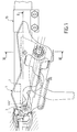
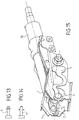
- Figure 1 is an axial longitudinal view of the energy absorption device of a steering column according to the invention.
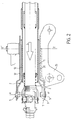
- Figure 2 is a half top view, and a half section along II-II of Figure 1.
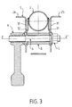
- Figure 3 is a cross section along III-III of Figure 1.
- FIG. 4 is a longitudinal view of the tube-body with its reinforcement square according to the invention shown in FIGS. 1 to 3.
- Figure 5 is a longitudinal view of the support according to the invention shown in Figures 1 to 3.
- Figure 6 is a longitudinal view of a variant of the support according to the invention.
- Figure 7 is a longitudinal view of a variant of the support according to the invention.
- Figure 8 is a longitudinal view of a variant of the support according to the invention.
- Figure 9 is a longitudinal view of a variant of the support according to the invention.
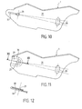
- Figure 10 is a longitudinal view of a variant of the support according to the invention.
- Figure 11 is a longitudinal view of a variant of the support according to the invention.
- Figure 12 is a partial section along XII-XII of Figure 11.
- Figure 13 shows a variant of a semi-axis.
- Figure 14 shows a variant of a semi-axis.
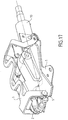
- Figure 15 is a perspective view corresponding to Figure 1.
- FIGS 16 and 17 show in perspective other embodiments of the invention.
- the energy absorption device according to the invention applies to a steering column of a motor vehicle, in particular adjustable in inclination, as can be seen in Figures 1, 2 and 3.
- the steering shaft of this column is mounted in a body tube 10 by means of bearings.
- the tube-body 10 is supported and locked on the body in the desired position.
- a support 1 is linked to the body and receives the body tube 10. This support 1 is the fixed part of the column and it does not move during the adjustment.
- a reinforcement square 2 is integral with the tube-body 10, and this assembly is the movable body, which is the part which supports the steering axis. This assembly moves during the adjustment around the axis XX '.
- This square-reinforcement assembly is conventional, but it could be replaced by an equivalent assembly intended to mount the tube-body 10 on the support 1.
- a blocking system is integral with the tube-body 10 by means of its reinforcement square 2 in the support 1.
- This blocking system has its blocking axis which is perpendicular to the axis of the steering column.
- the device of the invention comprises at least one deformation element which is secured to the support 1 and which is connected to the reinforcement square 2 of the support tube 10 via a connecting element.
- the deformation element is a tie rod referenced 3 mounted on the support 1.
- the support 1 is constituted by two uprights 31 and 32 which are connected to each other at their lower part by a connecting element 27.
- the two uprights and the connecting element can be a single piece or in several parts.
- Each of the two uprights 31 and 32 is extended at its upper part by a respective support face 25 and 26.
- Each of these support faces 25 and 26 is substantially perpendicular to the corresponding amount 31 and 32.
- Each support face 25 and 26 is applied against the body, and has a contour conjugated with the contour of the corresponding part of the body so as to be able to be fixed thereto.
- the two uprights 31 and 32 of the support 1 each have a slot 28 for passing the axis of the locking system. This light is dimensioned so as to allow the travel of the steering column for its tilt adjustment.
- the two uprights 31 and 32 are provided with a through hole 29 of the articulation of the reinforcement square 2 belonging to the tube-body 10. It will be noted that the lights 28 are not necessary for the steering columns which are not adjustable in direction. The invention also finds application for this type of column.
- the reinforcement square 2 consists of two uprights 11 and 12, which are connected to each other at their lower part by a connecting element 13.
- the reinforcement square 2 can be a single piece or an assembly of several rooms.
- the two uprights 11 and 12 are secured to the tube-body at their upper part by weld beads.
- Each of the uprights 11 and 12 is provided with a passage 14 intended to be crossed by the axis of the locking system.
- Each of these passages 14 has a clearance 15 which is produced by a notch 16.
- Each notch 16 is constituted by a semi-circular bottom 17 whose axis corresponds to the axis of the locking system, and this semi-circular bottom 17 East extended by two parallel sides 18, one relative to the other, and opening at the end 20 of the upright located on the side of the driver's steering wheel.
- the two uprights 11 and 12 are provided with a through hole 19 of the articulation of the reinforcement square 2 on the support 1.
- This through hole 19 is located at the other end 21 of each of the uprights which is opposite the driver.
- the system for blocking the tube-body 10 by its reinforcement square 2 in the support 1 is constituted by the clamping screw 4 which passes through each of the uprights 31 and 32 of the support 1, and each of the uprights 11 and 12 of the reinforcement square 2. More specifically, the clamping screw 4 passes through the lumen 28 of each of the uprights 31 and 32 of the support 1, and the passage 14 of each of the uprights 11 and 12 of the reinforcement square 2. In addition, the screw 4 is immobilized in rotation.
- a nut 7 is mounted at one of the threaded ends of the clamping screw 4, and this outside the corresponding upright 31 of the support 1.
- An operating member 6 is mounted at the other end of the clamping screw 4, and outside the corresponding upright 32 of the support 1.
- a spacer 8 is mounted on the operating screw 4 between the two uprights 11 and 12 of the reinforcement square 2.
- the actuator 6 which is tapped and which is mounted at the end of the threaded screw 4, generates by its rotation a movement in the axis of the screw 4 via the screw-nut system. This axial movement tends to more or less compress or release the reinforcement square 2 relative to the support 1, the tube-body 2 being wedged between the support 1 and the spacer 8.
- the clamping screw 4 is immobilized in rotation by a system not shown.
- the nut 7 makes it possible to adjust the tension in the clamping screw 4 of axis Z-Z '. The blocking of the reinforcement square relative to the support 1 is thus done only by adhesion.
- the articulation of the reinforcement square 2 of the tube-body 10 on the support 1 is constituted by two half-axes 5, which are each mounted on corresponding uprights 11 and 31 on the one hand, and 12 and 32 on the other hand .
- This joint constitutes the lower pivot of the steering column.
- the connecting element between the reinforcement square 2 and the deformation element constituted by the tie rod 3 is constituted by one of the two half-axes 5.
- the connecting element constituted by the half-axis 5 connects the tie rod as a deformation element, the corresponding amount 31 of the support 1, and the corresponding amount 11 of the reinforcement square 2.
- Each of these amounts 11 and 31 is provided with the through hole 19 and 29 of the semi-axis 5, the head of which is applied against the internal face of the upright 11 of the reinforcement square 2, and the end piece of which is applied against the external face of the element deformation, that is to say of the tie.
- the half-axis 5 can also be mounted so that the head is applied against the external face of the deformation element and the tip of which is applied against the internal face of the upright 11 of the reinforcement square 2.
- the other half-axis 5 connects the amount 32 of the support 1, and the corresponding amount 12 of the reinforcement square 2.
- Each of these amounts 12 and 32 is provided with the through hole 19 and 29 of the half-axis 5, the head is applied against the internal face of the upright 12 of the reinforcement square 2, and the end piece is applied against the external face of the corresponding upright 32 of the support 1.
- the half-axis 5 can also be mounted so that the head is applied against the external face of the corresponding upright 32 of the support 1, and the end piece of which is pressed against the face internal upright 12 of the reinforcement square 2.
- the half-axes 5 can be in variant embodiments: rivets, screws, axes with the head mounted on the internal or external side of the corresponding amount of the support 1 or of the reinforcement square 2, or on the side of the external face of the deformation element.
- the half-axes 5 can be made with an end piece constituted by a groove provided with a circlip or a stop ring as shown in FIG. 13.
- the axes can also be smooth with a self-tightening ring, which is the case in Figure 14.
- the two half-axes 5 can be replaced by a single axis.
- the deformation element which is constituted by the tie rod 3, is linked to the support 1 in the area of the passage lumen 28 of the corresponding upright 31.
- This tie rod 3 is drilled at the other end to receive the rod of the corresponding semi-axis 5.
- each of the uprights 31 and 32 of the support 1 is provided with a notch 30 on the through hole 29 of the semi-axis 5.
- This notch 30 has a width which is less than the diameter of the half-axis 5, so that in the event of an impact, each of the half-axes 5 linked to the reinforcement square 2 can escape from the support 1, passing through the corresponding notch 30, which allows the half axis 5 of the tie rod 3 to drive the latter in order to absorb the energy.
- the body tube 10 with its square-reinforcement 2 drives the deformation element constituted by the tie rod 3 in order to absorb the energy.
- Each of the passages 14 of the square reinforcement 2 being provided with the clearance 15 oriented in the direction of the driver's steering wheel, allows the square reinforcement 2 to be released from the blocking system.
- the tie rod 3 is linked to the support 1 by welding. Without departing from the scope of the invention, this tie rod 3 could be linked to the support 1 by crimping, riveting or screwing.
- the tie rod 3 is unique and asymmetrical.
- a tie rod 3 can be provided on each of the uprights 31 and 32 of the support 1, which would thus constitute a symmetrical system.
- Another embodiment of the invention shown in Figures 16 and 17 comprises as deformation element a single tie rod 3 placed above the steering axis, and connected to each of the half-axes 5, so as to produce also a symmetrical system.
- the deformation element may consist of a tie rod placed below the steering axis, and connected to each of the half-axes 5, so to also realize a symmetrical system.
- the operation of the energy absorption device according to the invention takes place as follows.
- the driver of the vehicle hits the steering wheel, he exerts a force on the tube-body 10 with his reinforcement square 2 in the direction of the arrow S as can be seen in FIG. 2.
- the reinforcement square 2 is retained on the support 1 by the two half-axes 5 and by the locking system.
- the notch 16 in the reinforcement square 2 allows the latter to escape from the blocking system.
- the reinforcement square 2 drives one end of the tie rod 3 via a half-axis 5, the other end remaining fixed on the support 1.
- the deformation of this tie rod 3 makes it possible to absorb the necessary energy. Its particular shape of the meander type allows it to deform over a distance which can be of the order of 20 to 50 mm.
- the effort for setting the device in motion is controlled by the interference between the diameter of the passage hole 29 of the articulation provided on each of the uprights 30 and 32 of the support 1, with the width of the notch 30 which exists. at the joint and the thickness of this support 1 at the notch.
- This effort for setting in motion includes the effort due to this interference increased by the adhesion effort at the level of the blocking system. This effort becomes zero after a few millimeters of the order of 5 to 15 mm for example.
- tie rod 3 i.e. the width of the waves, its thickness, the number of waves, the characteristics of the material make it possible to regulate the effort and the course, that is to say ultimately to regulate precisely the energy absorbed.
- the steering column can be further simplified in another embodiment of the invention by integrating the deformation element in the support 1.
- the connecting element is constituted by the half-axis 5 which connects the deformation element integrated into the uprights 31 and 32 of the support 1 and the corresponding uprights 11 and 12 of the reinforcement square 2.
- Each of these uprights 31, 32, 11 and 12 is provided with the through hole 19 and 29 of the semi-axis 5, whose head is applied against the internal face of the upright 11, 12 of the reinforcement square 2 and whose endpiece is applied against the external face of the upright 31, 32 corresponding to the support 1.
- the deformation element integrated into the support 1 is constituted by a zone in each of the uprights 31, 32 arranged around the passage hole 29 of the articulation of the reinforcement square 2 of the tube-body 10. This is then the deformation of the support 1 in the area where the half-axes 5 are located, which allows energy to be absorbed. Special arrangements in this area make it possible to control the force and the displacement of the reinforcement square 2 relative to the support 1.
- the body-tube shown in FIG. 4 with the reinforcement square 2 according to the invention can be mounted in the various alternative embodiments of the support 1 shown in FIGS. 5 to 12.
- FIG. 5 corresponds to the embodiment of the invention comprising a tie rod 3 as shown in FIGS. 1 to 3.
- Figures 6 to 12 show different alternative embodiments of the support 1, when the deformation element is integrated into this support in the area where the half-axes 5 are located.
- the zone of the deformation element comprises a cutout 33 in the form of a lunula, which is directed substantially in the direction of the axis of inclination, that is to say axis driven from the through hole 29 of the joint to the through lumen 28.
- the zone of the deformation element comprises a cutout 34 in the shape of a U which is directed approximately perpendicular to the axis of inclination.
- the zone of the deformation element comprises a cutout 35 in the form of two rafters, which are arranged on either side of the passage hole 29 of the joint, and which are directed in the direction of the tilt axis.
- the zone of the deformation element comprises a cutout 36 in the form of two openings, which are arranged on either side of passage holes 29 of the joint and directed substantially perpendicular to the 'tilt axis.
- the zone of the deformation element comprises a cutout 37 in the form of a lumen, which is arranged in the direction of the axis of inclination, and which opens into the through hole 29 of the joint.
- the zone of the deformation element comprises a return of the upright 31, 32 in the form of a tongue 38, which includes the passage hole 29 of the articulation, and which covers a notch 39 arranged in the direction of the tilt axis.
- the driver can also strike the inflated air bag and transmit the force to the steering wheel via this air bag.
Landscapes
- Engineering & Computer Science (AREA)
- Chemical & Material Sciences (AREA)
- Combustion & Propulsion (AREA)
- Transportation (AREA)
- Mechanical Engineering (AREA)
- Steering Controls (AREA)
- Vibration Dampers (AREA)
Applications Claiming Priority (2)
| Application Number | Priority Date | Filing Date | Title |
|---|---|---|---|
| FR9314260 | 1993-11-29 | ||
| FR9314260A FR2713188B1 (fr) | 1993-11-29 | 1993-11-29 | Dispositif d'absorption d'énergie pour colonne de direction de véhicule automobile. |
Publications (2)
| Publication Number | Publication Date |
|---|---|
| EP0655383A1 true EP0655383A1 (de) | 1995-05-31 |
| EP0655383B1 EP0655383B1 (de) | 1999-01-27 |
Family
ID=9453328
Family Applications (1)
| Application Number | Title | Priority Date | Filing Date |
|---|---|---|---|
| EP94402541A Expired - Lifetime EP0655383B1 (de) | 1993-11-29 | 1994-11-09 | Energieaufnehmende Einrichtung für die Lenksäule eines Kraftfahrzeugs |
Country Status (5)
| Country | Link |
|---|---|
| US (1) | US5673937A (de) |
| EP (1) | EP0655383B1 (de) |
| DE (1) | DE69416261T2 (de) |
| ES (1) | ES2126725T3 (de) |
| FR (1) | FR2713188B1 (de) |
Cited By (1)
| Publication number | Priority date | Publication date | Assignee | Title |
|---|---|---|---|---|
| EP1550599A1 (de) * | 2002-10-07 | 2005-07-06 | Toyota Jidosha Kabushiki Kaisha | Kollisionsenergie aufnehmende lenksäulenvorrichtung |
Families Citing this family (14)
| Publication number | Priority date | Publication date | Assignee | Title |
|---|---|---|---|---|
| FR2748250B1 (fr) * | 1996-05-03 | 1998-06-26 | Lemforder Nacam Sa | Dispositif de positionnement, lors d'un choc, d'une colonne de direction de vehicule automobile |
| JP3612971B2 (ja) | 1997-12-03 | 2005-01-26 | 日本精工株式会社 | 衝撃吸収式ステアリングコラム装置 |
| US6019391A (en) * | 1998-05-04 | 2000-02-01 | General Motors Corporation | Steering column for motor vehicle |
| FR2785863B1 (fr) * | 1998-11-12 | 2001-03-09 | Ecia Equip Composants Ind Auto | Ensemble de colonne de direction a absorption d'energie de choc, notamment pour vehicule automobile |
| GB2393157B (en) * | 2000-11-08 | 2004-05-12 | Nsk Steering Sys Europ Ltd | Collapsible steering column assembly for a vehicle |
| WO2004101345A2 (en) * | 2003-05-14 | 2004-11-25 | Toyota Jidosha Kabushiki Kaisha | Shock absorbing steering column support |
| US7334817B2 (en) * | 2004-09-02 | 2008-02-26 | Delphi Technologies, Inc. | Active energy absorption method using tilt and telescope positions |
| US20060042458A1 (en) * | 2004-09-02 | 2006-03-02 | Krj Industria E Comercio Ltda. | Device applied in electronic connectors of energy provided with unit of detonation incorporated in a button for detonation of cartridge with powder |
| US7306259B2 (en) * | 2004-10-14 | 2007-12-11 | Delphi Technologies, Inc. | Lock for tilting and telescoping steering column |
| US7827880B2 (en) * | 2005-03-21 | 2010-11-09 | Gm Global Technology Operations, Inc. | Steering column assembly with a quick release bolt |
| DE102007002091B4 (de) | 2007-01-09 | 2010-09-09 | Thyssenkrupp Technologies Ag | Lenksäule mit Crasheinrichtung |
| GB0816354D0 (en) * | 2008-09-06 | 2008-10-15 | Trw Ltd | Steering column assembly |
| DE112015001027T5 (de) * | 2014-02-27 | 2016-12-22 | Kyb Corporation | Lenkvorrichtung |
| JP7375462B2 (ja) * | 2019-10-24 | 2023-11-08 | 株式会社ジェイテクト | ステアリングコラム装置 |
Citations (5)
| Publication number | Priority date | Publication date | Assignee | Title |
|---|---|---|---|---|
| GB1523638A (en) * | 1974-12-28 | 1978-09-06 | Toyota Motor Co Ltd | Tiltable steering wheel assembly |
| DE2814145A1 (de) * | 1977-04-06 | 1978-10-19 | Koyo Seiko Co | Halterungsvorrichtung zur befestigung einer lenksaeule |
| DE3619125C1 (de) * | 1986-06-06 | 1987-10-22 | Daimler Benz Ag | Aufnahmevorrichtung fuer eine verstellbare Lenksaeule eines Kraftwagens |
| GB2244032A (en) * | 1990-05-08 | 1991-11-20 | Torrington Co | Mechanism for absorbing impact energy transmitted through a vehicle steering column |
| GB2264906A (en) * | 1992-03-13 | 1993-09-15 | Nsk Ltd | Collapsible steering column |
-
1993
- 1993-11-29 FR FR9314260A patent/FR2713188B1/fr not_active Expired - Lifetime
-
1994
- 1994-11-09 DE DE69416261T patent/DE69416261T2/de not_active Expired - Fee Related
- 1994-11-09 ES ES94402541T patent/ES2126725T3/es not_active Expired - Lifetime
- 1994-11-09 EP EP94402541A patent/EP0655383B1/de not_active Expired - Lifetime
- 1994-11-15 US US08/340,145 patent/US5673937A/en not_active Expired - Lifetime
Patent Citations (5)
| Publication number | Priority date | Publication date | Assignee | Title |
|---|---|---|---|---|
| GB1523638A (en) * | 1974-12-28 | 1978-09-06 | Toyota Motor Co Ltd | Tiltable steering wheel assembly |
| DE2814145A1 (de) * | 1977-04-06 | 1978-10-19 | Koyo Seiko Co | Halterungsvorrichtung zur befestigung einer lenksaeule |
| DE3619125C1 (de) * | 1986-06-06 | 1987-10-22 | Daimler Benz Ag | Aufnahmevorrichtung fuer eine verstellbare Lenksaeule eines Kraftwagens |
| GB2244032A (en) * | 1990-05-08 | 1991-11-20 | Torrington Co | Mechanism for absorbing impact energy transmitted through a vehicle steering column |
| GB2264906A (en) * | 1992-03-13 | 1993-09-15 | Nsk Ltd | Collapsible steering column |
Cited By (3)
| Publication number | Priority date | Publication date | Assignee | Title |
|---|---|---|---|---|
| EP1550599A1 (de) * | 2002-10-07 | 2005-07-06 | Toyota Jidosha Kabushiki Kaisha | Kollisionsenergie aufnehmende lenksäulenvorrichtung |
| EP1550599A4 (de) * | 2002-10-07 | 2007-01-03 | Toyota Motor Co Ltd | Kollisionsenergie aufnehmende lenksäulenvorrichtung |
| US7240922B2 (en) | 2002-10-07 | 2007-07-10 | Toyota Jidosha Kabushiki Kaisha | Impact-absorbing steering column apparatus |
Also Published As
| Publication number | Publication date |
|---|---|
| DE69416261T2 (de) | 1999-09-30 |
| DE69416261D1 (de) | 1999-03-11 |
| EP0655383B1 (de) | 1999-01-27 |
| ES2126725T3 (es) | 1999-04-01 |
| US5673937A (en) | 1997-10-07 |
| FR2713188A1 (fr) | 1995-06-09 |
| FR2713188B1 (fr) | 1996-02-23 |
Similar Documents
| Publication | Publication Date | Title |
|---|---|---|
| EP0755844B1 (de) | Energieaufnehmende und führende Einrichtung für die Lenksäule eines Kraftfahrzeugs | |
| EP0655383B1 (de) | Energieaufnehmende Einrichtung für die Lenksäule eines Kraftfahrzeugs | |
| EP0755842B1 (de) | System zur Führung und Verriegelung für eine Kraftfahrzeuglenksäule | |
| EP1345804B1 (de) | Vorrichtung zum festklemmen eines einstellbaren elements bezüglich einer stützanordnung | |
| EP2155531B1 (de) | Elektrische klemmvorrichtung für eine einstellbare motorfahrzeug-lenksäule | |
| EP1176082B1 (de) | Pyrotechnisch einstellbare Energieabsorptionseinrichtung längs der Achse einer Kraftfahrzeuglenksäule | |
| EP3145790B1 (de) | In die tiefe einstellbarer lenksäulemechanismus mit versenkbarem anschlag | |
| EP0662414A1 (de) | Energieabsorbierende Einrichtung, insbesondere für eine Kraftfahrzeuglenksäule | |
| EP0662413B1 (de) | Energieabsorbierende Einrichtung für eine Kraftfahrzeuglenksäule | |
| WO2008145916A2 (fr) | Dispositif d'absorption d'énergie pour siège de véhicule automobile, assemblage et ensemble comprenant le dispositif | |
| WO2008142312A1 (fr) | Dispositif de maintien en position a absorption d'energie d'une colonne de direction de vehicule automobile | |
| EP0805092A1 (de) | Bei einem Stoss aktive Rückzueinrichtung einer Kraftfahrzeug-Lenksäule | |
| EP1336546B1 (de) | Einstell- Einrichtung eines Energieaufnehme-Systems einer Kraftfahrzeuglenksäule | |
| EP3724057B1 (de) | Lenksäule mit verstellanschlag | |
| FR2881707A1 (fr) | Dispositif d'absorption instantanee d'energie d'une colonne de direction de vehicule automobile | |
| EP0800978B1 (de) | Stossenergieaufnehmende Lenksäuleneinrichtung,insbesondere für ein Kraftfahrzeug | |
| FR2768203A1 (fr) | Securite d'engagement a basculement d'un dispositif de maintien en position d'un systeme de serrage de deux elements | |
| FR2841524A1 (fr) | Dispositif d'absorption d'energie d'une colonne de direction de vehicule automobile | |
| EP1359082B1 (de) | Positionsanpassungseinrichtung einer einstellbaren Kraftfahrzeuglenksäule | |
| EP0443910A1 (de) | Sperrvorrichtung eines tubulären Organs, insbesondere einer Kraftfahrzeuglenksäule | |
| EP1623899B1 (de) | Pedalaufbau für ein Kraftfahrzeug | |
| FR2778704A1 (fr) | Dispositif de serrage d'un systeme de reglage en position d'un element par rapport a un autre element | |
| FR2742718A1 (fr) | Ensemble de colonne de direction reglable en position et a absorption d'energie de choc, notamment pour vehicule automobile | |
| WO1995023299A1 (fr) | Dispositif d'absorption d'energie par deformation plastique, notamment pour volant de direction de vehicule, et volant de direction equipe d'un tel dispositif | |
| FR2714650A1 (fr) | Dispositif d'absorption d'énergie avec amortisseur, pour colonne de direction de véhicule automobile. |
Legal Events
| Date | Code | Title | Description |
|---|---|---|---|
| PUAI | Public reference made under article 153(3) epc to a published international application that has entered the european phase |
Free format text: ORIGINAL CODE: 0009012 |
|
| 17P | Request for examination filed |
Effective date: 19950202 |
|
| AK | Designated contracting states |
Kind code of ref document: A1 Designated state(s): DE ES GB IT |
|
| 17Q | First examination report despatched |
Effective date: 19960306 |
|
| RAP1 | Party data changed (applicant data changed or rights of an application transferred) |
Owner name: LEMFOERDER NACAM SA |
|
| GRAG | Despatch of communication of intention to grant |
Free format text: ORIGINAL CODE: EPIDOS AGRA |
|
| GRAG | Despatch of communication of intention to grant |
Free format text: ORIGINAL CODE: EPIDOS AGRA |
|
| GRAH | Despatch of communication of intention to grant a patent |
Free format text: ORIGINAL CODE: EPIDOS IGRA |
|
| GRAH | Despatch of communication of intention to grant a patent |
Free format text: ORIGINAL CODE: EPIDOS IGRA |
|
| GRAA | (expected) grant |
Free format text: ORIGINAL CODE: 0009210 |
|
| AK | Designated contracting states |
Kind code of ref document: B1 Designated state(s): DE ES GB IT |
|
| REF | Corresponds to: |
Ref document number: 69416261 Country of ref document: DE Date of ref document: 19990311 |
|
| REG | Reference to a national code |
Ref country code: ES Ref legal event code: FG2A Ref document number: 2126725 Country of ref document: ES Kind code of ref document: T3 |
|
| GBT | Gb: translation of ep patent filed (gb section 77(6)(a)/1977) |
Effective date: 19990318 |
|
| ITF | It: translation for a ep patent filed | ||
| PLBE | No opposition filed within time limit |
Free format text: ORIGINAL CODE: 0009261 |
|
| STAA | Information on the status of an ep patent application or granted ep patent |
Free format text: STATUS: NO OPPOSITION FILED WITHIN TIME LIMIT |
|
| 26N | No opposition filed | ||
| PGFP | Annual fee paid to national office [announced via postgrant information from national office to epo] |
Ref country code: ES Payment date: 20001005 Year of fee payment: 7 |
|
| PGFP | Annual fee paid to national office [announced via postgrant information from national office to epo] |
Ref country code: GB Payment date: 20001108 Year of fee payment: 7 |
|
| PG25 | Lapsed in a contracting state [announced via postgrant information from national office to epo] |
Ref country code: GB Free format text: LAPSE BECAUSE OF NON-PAYMENT OF DUE FEES Effective date: 20011109 |
|
| PG25 | Lapsed in a contracting state [announced via postgrant information from national office to epo] |
Ref country code: ES Free format text: LAPSE BECAUSE OF NON-PAYMENT OF DUE FEES Effective date: 20011110 |
|
| REG | Reference to a national code |
Ref country code: GB Ref legal event code: IF02 |
|
| GBPC | Gb: european patent ceased through non-payment of renewal fee |
Effective date: 20011109 |
|
| PGFP | Annual fee paid to national office [announced via postgrant information from national office to epo] |
Ref country code: DE Payment date: 20031210 Year of fee payment: 10 |
|
| REG | Reference to a national code |
Ref country code: ES Ref legal event code: FD2A Effective date: 20021213 |
|
| PG25 | Lapsed in a contracting state [announced via postgrant information from national office to epo] |
Ref country code: DE Free format text: LAPSE BECAUSE OF NON-PAYMENT OF DUE FEES Effective date: 20050601 |
|
| PG25 | Lapsed in a contracting state [announced via postgrant information from national office to epo] |
Ref country code: IT Free format text: LAPSE BECAUSE OF NON-PAYMENT OF DUE FEES;WARNING: LAPSES OF ITALIAN PATENTS WITH EFFECTIVE DATE BEFORE 2007 MAY HAVE OCCURRED AT ANY TIME BEFORE 2007. THE CORRECT EFFECTIVE DATE MAY BE DIFFERENT FROM THE ONE RECORDED. Effective date: 20051109 |