EP0655110B1 - Einheit mit flüssigkeit und elastomer - Google Patents
Einheit mit flüssigkeit und elastomer Download PDFInfo
- Publication number
- EP0655110B1 EP0655110B1 EP19930920276 EP93920276A EP0655110B1 EP 0655110 B1 EP0655110 B1 EP 0655110B1 EP 19930920276 EP19930920276 EP 19930920276 EP 93920276 A EP93920276 A EP 93920276A EP 0655110 B1 EP0655110 B1 EP 0655110B1
- Authority
- EP
- European Patent Office
- Prior art keywords
- fluid
- variable
- elastomer
- passageway
- accordance
- Prior art date
- Legal status (The legal status is an assumption and is not a legal conclusion. Google has not performed a legal analysis and makes no representation as to the accuracy of the status listed.)
- Expired - Lifetime
Links
- 229920001971 elastomer Polymers 0.000 title claims description 37
- 239000000806 elastomer Substances 0.000 title claims description 37
- 239000012530 fluid Substances 0.000 claims abstract description 58
- 230000000712 assembly Effects 0.000 claims description 12
- 238000000429 assembly Methods 0.000 claims description 12
- 230000007704 transition Effects 0.000 claims description 2
- 238000007789 sealing Methods 0.000 claims 1
- 238000013016 damping Methods 0.000 abstract description 25
- 230000035945 sensitivity Effects 0.000 abstract 1
- 230000033001 locomotion Effects 0.000 description 5
- 238000010276 construction Methods 0.000 description 3
- 125000006850 spacer group Chemical group 0.000 description 3
- XAGFODPZIPBFFR-UHFFFAOYSA-N aluminium Chemical compound [Al] XAGFODPZIPBFFR-UHFFFAOYSA-N 0.000 description 2
- 229910052782 aluminium Inorganic materials 0.000 description 2
- 239000002131 composite material Substances 0.000 description 2
- 230000006835 compression Effects 0.000 description 2
- 238000007906 compression Methods 0.000 description 2
- 244000043261 Hevea brasiliensis Species 0.000 description 1
- 230000008602 contraction Effects 0.000 description 1
- 230000007797 corrosion Effects 0.000 description 1
- 238000005260 corrosion Methods 0.000 description 1
- 238000006073 displacement reaction Methods 0.000 description 1
- 238000009434 installation Methods 0.000 description 1
- 229920003052 natural elastomer Polymers 0.000 description 1
- 229920001194 natural rubber Polymers 0.000 description 1
- 229920001296 polysiloxane Polymers 0.000 description 1
- 230000001629 suppression Effects 0.000 description 1
- 230000003245 working effect Effects 0.000 description 1
Images




Classifications
-
- F—MECHANICAL ENGINEERING; LIGHTING; HEATING; WEAPONS; BLASTING
- F16—ENGINEERING ELEMENTS AND UNITS; GENERAL MEASURES FOR PRODUCING AND MAINTAINING EFFECTIVE FUNCTIONING OF MACHINES OR INSTALLATIONS; THERMAL INSULATION IN GENERAL
- F16F—SPRINGS; SHOCK-ABSORBERS; MEANS FOR DAMPING VIBRATION
- F16F13/00—Units comprising springs of the non-fluid type as well as vibration-dampers, shock-absorbers, or fluid springs
- F16F13/04—Units comprising springs of the non-fluid type as well as vibration-dampers, shock-absorbers, or fluid springs comprising both a plastics spring and a damper, e.g. a friction damper
- F16F13/06—Units comprising springs of the non-fluid type as well as vibration-dampers, shock-absorbers, or fluid springs comprising both a plastics spring and a damper, e.g. a friction damper the damper being a fluid damper, e.g. the plastics spring not forming a part of the wall of the fluid chamber of the damper
- F16F13/24—Units comprising springs of the non-fluid type as well as vibration-dampers, shock-absorbers, or fluid springs comprising both a plastics spring and a damper, e.g. a friction damper the damper being a fluid damper, e.g. the plastics spring not forming a part of the wall of the fluid chamber of the damper the central part of the unit being supported by one element and both extremities of the unit being supported by a single other element, i.e. double acting mounting
-
- B—PERFORMING OPERATIONS; TRANSPORTING
- B64—AIRCRAFT; AVIATION; COSMONAUTICS
- B64C—AEROPLANES; HELICOPTERS
- B64C27/00—Rotorcraft; Rotors peculiar thereto
- B64C27/32—Rotors
- B64C27/35—Rotors having elastomeric joints
-
- F—MECHANICAL ENGINEERING; LIGHTING; HEATING; WEAPONS; BLASTING
- F16—ENGINEERING ELEMENTS AND UNITS; GENERAL MEASURES FOR PRODUCING AND MAINTAINING EFFECTIVE FUNCTIONING OF MACHINES OR INSTALLATIONS; THERMAL INSULATION IN GENERAL
- F16F—SPRINGS; SHOCK-ABSORBERS; MEANS FOR DAMPING VIBRATION
- F16F13/00—Units comprising springs of the non-fluid type as well as vibration-dampers, shock-absorbers, or fluid springs
- F16F13/04—Units comprising springs of the non-fluid type as well as vibration-dampers, shock-absorbers, or fluid springs comprising both a plastics spring and a damper, e.g. a friction damper
- F16F13/06—Units comprising springs of the non-fluid type as well as vibration-dampers, shock-absorbers, or fluid springs comprising both a plastics spring and a damper, e.g. a friction damper the damper being a fluid damper, e.g. the plastics spring not forming a part of the wall of the fluid chamber of the damper
- F16F13/08—Units comprising springs of the non-fluid type as well as vibration-dampers, shock-absorbers, or fluid springs comprising both a plastics spring and a damper, e.g. a friction damper the damper being a fluid damper, e.g. the plastics spring not forming a part of the wall of the fluid chamber of the damper the plastics spring forming at least a part of the wall of the fluid chamber of the damper
-
- F—MECHANICAL ENGINEERING; LIGHTING; HEATING; WEAPONS; BLASTING
- F16—ENGINEERING ELEMENTS AND UNITS; GENERAL MEASURES FOR PRODUCING AND MAINTAINING EFFECTIVE FUNCTIONING OF MACHINES OR INSTALLATIONS; THERMAL INSULATION IN GENERAL
- F16F—SPRINGS; SHOCK-ABSORBERS; MEANS FOR DAMPING VIBRATION
- F16F2222/00—Special physical effects, e.g. nature of damping effects
- F16F2222/02—Special physical effects, e.g. nature of damping effects temperature-related
-
- Y—GENERAL TAGGING OF NEW TECHNOLOGICAL DEVELOPMENTS; GENERAL TAGGING OF CROSS-SECTIONAL TECHNOLOGIES SPANNING OVER SEVERAL SECTIONS OF THE IPC; TECHNICAL SUBJECTS COVERED BY FORMER USPC CROSS-REFERENCE ART COLLECTIONS [XRACs] AND DIGESTS
- Y10—TECHNICAL SUBJECTS COVERED BY FORMER USPC
- Y10T—TECHNICAL SUBJECTS COVERED BY FORMER US CLASSIFICATION
- Y10T137/00—Fluid handling
- Y10T137/7722—Line condition change responsive valves
- Y10T137/7837—Direct response valves [i.e., check valve type]
- Y10T137/7847—With leak passage
Definitions
- This invention relates to the area of fluid-and-elastomer devices. Specifically, the invention relates to the area of fluid-and-elastomer devices for providing damping for lead-lag motions of a helicopter rotor blade.
- Additional damping can be added, over and above what is available in an elastomeric damper, by incorporating a fluid within the damper to provide damping at certain predetermined, or tuned, frequencies.
- the commonly assigned US patent 4,811,919 to Jones describes the addition of fluid to an elastomeric mounting which is suitable for mounting an aircraft engine to a strut, and also describes the means for compensating for the fluid expansion due to temperature changes.
- US patent 4,236,607 to Hawles et al. describes a vibration suppression system wherein the fluid passes through the inner member of the mounting to provide amplified counter inertial forces.
- US patent 4,566,677 to Le Pierres describes a damped fluid-and-elastomeric, lead-lag damper for helicopter rotor blades, whereby the fluid is used to add additional damping over and above what is available from the elastomer alone.
- this damper is axially-acting and cannot carrying vertical loads due to flapping, which must be accommodated in bearingless rotor systems.
- US patent 5,004,215 to Aubry et al. (EP-A-0 334 716) describes another axially acting strut-type damper with linear damping by incorporating a viscous fluid. Again, this device cannot carry vertical loads due to flapping motions of the rotor blade, a normally required feature of dampers which are to be used in bearingless rotor systems.
- Another objective is to provide a fluid-and-elastomer, lead-lag damper for use on a helicopter rotor system which provides linear rotor blade damping as a function of amplitude and also is capable of carrying vertical flap loads.
- the present invention consists in a fluid-and-elastomer device having the features of claims 1.
- the passageway assembly can provide linear damping and pressure relief, all within one integrated package.
- the fluid-and-elastomer damper can be utilized to prcvide a damping loss factor of about 1.3 and can be used in bearingless rotor systems.
- the bearingless rotor system generally includes a rotor hub 11 which is preferably of composite construction and which attaches to a mast (not shown) of a helicopter, and a centering bearing 12 or other intermediate member which is generally an elastomeric bearing and which is attached to rotor hub 11 via a shaft 13 , or other means. It also includes a rotor cuff 14 which surrounds the portion of the rotor hub 11 shown and which is preferably of aluminum, but may be of composite construction.
- a pitch horn 18 is generally attached to the rotor cuff 14 such that pitch control can be imparted to the cuff 14 and rotor blades (not shown).
- the system shown also includes the fluid device 20 of the present invention, as contrasted with prior systems generically known as bearingless rotor systems 10 , which utilized purely elastomeric dampers.
- the fluid device 20 describe herein was initially conceived for use in the bearingless rotor environment; however, more conventional installations can be envisioned, as well.
- the fluid device 20 includes a piston 22 which pumps the fluid within the fluid device 20 and which attaches to the previously mentioned centering bearing 12 , or other intermediate member which acts as the means for connecting or interconnecting to the rotor hub 11 .
- the fluid device 20 includes an elastomer section 24 , of preferably laminated shim-and-elastomer construction, which defines a portion of a first variable-volume chamber 26 and which also defines a portion of a like, and generally opposed, second variable-volume chamber 28.
- the elastomer section 24 also provides the stiffness for reacting vertical loads which are due to relative flapping motions which occur between the rotor cuff 14 and rotor hub 11 .
- a housing 30 also defines a portion of the first and second variable-volume chambers 26 and 28, and encloses virtually the entire inner workings within the fluid device 20 .
- the housing 30 is preferably made of aluminum and is anodized for corrosion protection and includes a first half 32 and a second half 34 which are bolted together, recessed in, and fastened to, the rotor cuff 14 .
- the piston 22 may include two primary passageways formed therethrough for connecting, and allowing damping fluid 38 to flow between, the first variable-volume chamber 26 and second variable-volume chamber 28 .
- the fluid 38 is contained within, and substantially fills, the first variable-volume chamber 26 , second variable-volume chamber 28 , and interconnecting passageways.
- the fluid device 20 also includes pressurizer 40 of the compressed-air type for statically pressurizing the fluid 38 such that cavitation of the fluid 38 under large amplitudes does not occur.
- pressurizer 40 also compensates for expansion and contraction of the fluid 38 due to temperature changes.
- the pressurizer 40 includes a third chamber 42 which is annular shaped and is interconnected to one of said first and second chambers 26 and 28 by way of a small passageway 43, a separator 44 such as a flexible diaphragm which includes seal 45, a fourth chamber 46 which is annular in shape and which is filled, under pressure, with air or the like, a plate 48 for attaching to second half 34 by way of bolts 49 , and a valve 50 for providing the access for pressurization.
- a separator 44 such as a flexible diaphragm which includes seal 45
- a fourth chamber 46 which is annular in shape and which is filled, under pressure, with air or the like
- a plate 48 for attaching to second half 34 by way of bolts 49
- a valve 50 for providing the access for pressurization.
- the piston 22 includes an inner member 55 , a spacer 56 which is located relative to the inner member 55 by way of pins 58 , and a fastener 60. Threads 59 formed within fastener 60 attach to a stud (not shown) which is, in turn, attached to centering bearing 12 ( Fig. 1 ).
- Tightening fastener 60 urges centering bearing 12 ( Fig. 1 ) in contact with spacer 56.
- the bores 62 accept pins which are press fit into the centering bearing 12 ( Fig. 1 ) in the same manner as the pins 58 are installed in the spacer 59.
- a pin 64 is cross drilled and pressed into the inner member 55 such that safety wire (not shown) can be placed through the cross-drilled hole in the fastener 60 and also through cross-drilled hole in pin 64, and thus, restrain fastener 60 from turning and unscrewing.
- FIG. 3 Another view of the fluid device 20 is illustrated in Fig. 3 .
- the shims 66 are flat and extend in a plane perpendicular to the line of vertical load application A.
- Two primary passageways 68 extend between first variable- and second variable-volume chambers 26 and 28 ( Fig. 2 ).
- the elastomer section 24 wraps completely around the inner member 55 and is preferably a natural rubber elastomer with a loss factor (tan delta) of less than 0.4, and more preferably a loss factor (tan delta) of about 0.1.
- the elastomer section 24 is preferably integrally bonded to outer member 53 and to inner member 55 . Further, close tolerances between the outer member 53 and the inner surfaces 70 of the upper and lower halves 32 and 34 will allow fluid 38 ( Fig. 2 ) to flow only through the primary passageways 68.
- Fluid device 20 is shown with bores 74 through flanges 72 in first and second halves 32 ( Fig. 3 ) and 34 of housing 30.
- Fastener 60 includes an internal hex as shown. Further, all bolts 49 and bolts 76 are wired together by safety wire 75 .
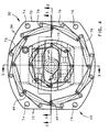
- FIG. 5 Another view of the fluid device 20 is illustrated in Fig. 5 wherein one of the passageway assemblies 80A is shown installed in the inner member 55.
- a like passageway 80B is shown in Fig. 6 .
- the assemblies 80A and likewise 80B include a floating member 82 which has a seat 84 which seals against a similar seat formed in inner member 55.
- the assemblies 80A and 80B also includes a spring 86 which biases the seat 84 against inner member 55 and an adjuster 88 which adjusts the compression of spring 86 .
- the floating member 82 includes a central portion 90 over which the spring 86 is located and slides. The central portion 90 also slides freely within bore 92 formed in adjuster 88 .
- the adjuster 88 includes screwdriver slots 96 and/or a wrench profile for providing for adjustment.
- Integral with the assembly 80A and also 80B are the primary passageways 68 having a diameter D and a length L which are chosen to provide linearity, such that for selected ranges, the stiffnesses K*, K' and K" remain constant.
- K* is the complex stiffness
- K' is the real, or in-phase stiffness
- K" is the imaginary, or out-of-phase, stiffness.
- the present invention fluid device 20 provides complex stiffness K* which is linear for amplitudes of 0.025 to 0.89 cms (0.01 to 0.35 inch) with values of stiffness K* between approximately 1.29 x 10 5 - 1 x 10 5 kg-m -1 (7200 lb/in and 5600 lb/in) at approximately 5 Hz.
- the linear range is defined as the range wherein not more than 15% deviation from nominal K* is present. Linear damping is achieved by the appropriate choice of diameter D, and length L and viscosity ⁇ .
- the diameter D of the present invention should be in the range of 0.13 - 1.27 cms (0.05 and 0.5 inch), and the length L should be in the range of 0.64 - 6.35 cms (0.25 and 2.5 inch).
- the kinematic viscosity should be in the range of between 1 x 10 -3 to 1 x 10 -2 m 2 .s -1 (1,000 and 10,000 centistokes (cs)) and more preferably 2x10 -3 m 2 .s -1 (2000 cs).
- One very distinct advantage is that the present invention allows for linear damping level regardless of the direction of fluid flow.
- the transition zone 94 which occurs at the entrance and exit to the passageway 80 each have a diameter D ' and a length L ' such that the conditions imposed for each direction result in uniform losses. This is particularly important in systems which require linearity as a function of amplitude in each direction.
- FIG. 6 shows the fluid device 20 and two passageway assemblies 80A and 80B .
- the passageway assemblies 80A and 80B allow fluid 38 to flow between the chambers 26 and 28 .
- the two primary passageways 68 within the assemblies 80A and 80B are in fluid-parallel relationship and are unblocked for normal conditions.
- the damping level is also linear as a function of amplitude, due to the appropriate choice of the diameter D , length L and kinematic viscosity ⁇ of the damping fluid. These parameters can be adjusted to allow for linearity of K*, K', and K".
- the flow of fluid 38 through each primary passageway 68 is approximately equal.
- auxiliary flow path 98 Fig. 3
- the passageway 68 and the pressure-relief valve are integrated into one package within the passageway assemblies 80A and 80B .
- the floating members 82 of the passageway assemblies 80A and 80B act in different directions.
- the floating member 82 of each assembly 80A and 80B are oriented to act in one direction only.
- the auxiliary flow path can only flow in one direction for providing pressure relief.
- passageway assembly 80A only opens when the threshold fluid pressure differential is exceeded and the highest pressure occurs in chamber 26 .
- passageway assembly 80B only opens when the threshold fluid-pressure differential is exceeded and the highest pressure occurs in chamber 28 . In this way, even when under going a pressure-relief situation, equal amounts of damping can be present in each direction.
- these pressure-relief valves within the assemblies 80A and 80B act in such a manner that when normal conditions occur, the seats 84 of floating members 82 are in contact with the inner member 55 and the auxiliary flow path 98 has no fluid flowing in it. Upon reaching the threshold pressure, the floating member 82 is opened, and fluid 38 flow is channeled through the auxiliary flow path 98, such as the plurality of channels shown.
- the assembly 80A includes a floating member 82 which includes a valve face 84 which seals against a seat formed in inner member 55 .
- the assembly 80A also includes a spring 86 which biases or spring loads the valve face 84 against the seat in the inner member 55.
- the coil spring shown has a spring rate of about 75 lb/in.
- the assemblies also include an adjuster 88 which adjusts the compression of spring 86.
- the adjuster 88 includes screwdriver slots 96 and/or a wrench profile and is threaded to providing the means for adjustment of the amount of pressure exerted on the seat 84 point of break, or the point at which pressure relief starts.
- This pressure relief/passageway device is integrated into one compact package which can be used to limit the pressure in one direction. In order to limit the pressure in two directions, two opposed assemblies 80A and 80B are used.
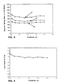
- Fig. 8 illustrates a performance curve for the fluid device 20. This particular damper was tuned to provide linearity in K" over a broad range of amplitudes and at about 5 Hz. The parameters can be adjusted such that linearity occurs at other frequencies over a broad frequency range.
- Fig. 9 illustrates a performance curve for the fluid device 20 .
- the loss factor (tan delta) is shown as being relatively insensitive to amplitude or linear as a function of amplitude.
- the loss factor for this embodiment can range from about 1.3 to 1.1 depending on amplitude.
- the K' component is relative low and in fact, the real component K' is less than the damping component K".
Landscapes
- Engineering & Computer Science (AREA)
- General Engineering & Computer Science (AREA)
- Mechanical Engineering (AREA)
- Aviation & Aerospace Engineering (AREA)
- Fluid-Damping Devices (AREA)
- Combined Devices Of Dampers And Springs (AREA)
Claims (13)
- Fluid- und Elastomereinrichtung (20) mit einer ersten Kammer (26) mit variablem Volumen, einer zweiten Kammer (28) mit variablem Volumen, einem Gehäuse (30), welches einen Teil der ersten und der zweiten Kammer mit variablem Volumen definiert, einer lösbaren Durchlaßanordnung (80A), die die erste und die zweite Kammer mit variablem Volumen verbindet, wobei die Durchlaßanordnung darüber hinaus einen Primärdurchlaß (68) umfaßt, der in die lösbare Durchlaßanordnung integriert ist, mit einem Einlaß und einem Auslaß, die unter normalen Betriebsbedingungen unblockiert sind und mit Übergangszonen gleicher Länge L und Durchmesser D angrenzend an den Einlaß und den Auslaß, die zu gleichen Verlusten in jeder Richtung führen, einem Hilfsströmungsdurchlaß (98), der in die lösbare Durchlaßanordnung integriert ist derart, daß eine Strömung durch den Hilfsdurchlaß von der ersten und der zweiten Kammer mit variablem Volumen zu der jeweils anderen Kammer mit variablem Volumen in einer Richtung gestattet ist, wenn das Druckdifferential oberhalb eines Druckschwellenwertes liegt, welcher eintritt zwischen der ersten und der zweiten Kammer mit variablem Volumen, und ein Fluid enthalten ist innerhalb der ersten und der zweiten Kammer mit variablem Volumen sowie dem Primärdurchlaß, wobei durch eine Verschiebung eines Kolbens (22) relativ zum Gehäuse Fluid durch den Primärdurchlaß zwischen der ersten und der zweiten Kammer mit variablem Volumen führbar ist,
gekennzeichnet durcha) einen einzelnen Elastomerabschnitt (24), der einen Teil der ersten und der zweiten Kammer mit variablem Volumen definiert, wobei der Elastomerabschnitt eine Hochvolumensteifigkeit für die erste und die zweite Kammer mit variablem Volumen bereitstellt und b) einen gemeinsamen Einlaß für die Primär- und Hilfsströmungsdurchlässe. - Fluid- und Elastomereinrichtung nach Anspruch 1, dadurch gekennzeichnet, daß das Fluid innerhalb des Dämpfers eine kinematische Viskosität besitzt im Bereich zwischen 1.000 und 10.000 cs.
- Fluid- und Elastomereinrichtung nach Anspruch 2, dadurch gekennzeichnet, daß das Fluid innerhalb des Dämpfers eine kinematische Viskosität von etwa 2.000 cs besitzt.
- Fluid- und Elastomereinrichtung nach Anspruch 1, dadurch gekennzeichnet, daß der Primärdurchlaß eine Länge L besitzt, die im Bereich von 0,625 cm und 6,25 cm (0,25 und 2,5 Zoll) liegt.
- Fluid- und Elastomereinrichtung nach Anspruch 1, dadurch gekennzeichnet, daß der Primärdurchlaß einen Durchmesser D im Bereich zwischen 0,125 cm und 1,25 cm (0,05 und 0,5 Zoll) besitzt.
- Fluid- und Elastomereinrichtung nach Anspruch 1, dadurch gekennzeichnet, daß der Elastomerabschnitt ein Elastomer mit einem Verlustfaktor von weniger als 0,4 aufweist.
- Fluid- und Elastomereinrichtung nach Anspruch 1, gekennzeichnet durch eine Einrichtung (50) zur Unterdrucksetzung des Fluids.
- Fluid- und Elasatomereinrichtung nach Anspruch 1, dadurch gekennzeichnet, daß das Fluid eine kinematische Viskosität µ besitzt und der Durchmesser D, die Länge L und die kinematische Viskosität µ derart ausgewählt sind, daß sich eine Steifigkeit K*, K' und K" ergibt, die linear ist als Funktion der Amplitude.
- Fluid- und Elastomereinrichtung nach Anspruch 1, gekennzeichnet durch ein Schwimmelement innerhalb der Durchlaßanordnung, welches unter der Belastung einer Schraubenfeder steht mit einer Federkennung von 1.339 kg/m (75 lb/in).
- Fluid- und Elastomereinrichtung nach Anspruch 1, dadurch gekennzeichnet, daß der Hilfsdurchlaß eine Mehrzahl von Kanälen umfaßt.
- Fluid- und Elastomereinrichtung nach Anspruch 1, dadurch gekennzeichnet, daß die Fluid- und Elastomereinrichtung zwei Durchlaßanordnungen umfaßt, die hierin ausgebildet sind, von denen jede in eine andere Richtung wirkt derart, daß die eine das Druckdifferential zwischen der ersten und der zweiten Kammer mit variablem Volumen in einer Richtung begrenzt und die andere das Druckdifferential zwischen der ersten und der zweiten Kammer mit variablem Volumen in der anderen Richtung begrenzt.
- Fluid- und Elastomereinrichtung nach Anspruch 1, dadurch gekennzeichnet, daß die Durchlaßanordnung ein Schwimmelement umfaßt mit einem Sitz zur Abdichtung der Strömung des Fluids durch den Hilfsströmungsdurchlaß.
- Fluid- und Elastomereinrichtung nach Anspruch 12, gekennzeichnet durch eine Einrichtung zur Einstellung des Druckausmaßes auf den Sitz.
Applications Claiming Priority (3)
| Application Number | Priority Date | Filing Date | Title |
|---|---|---|---|
| US07/934,402 US5374039A (en) | 1992-08-24 | 1992-08-24 | Fluid-and-elastomer support device |
| US934402 | 1992-08-24 | ||
| PCT/US1993/007925 WO1994004842A1 (en) | 1992-08-24 | 1993-08-19 | Fluid-and-elastomer device |
Publications (3)
| Publication Number | Publication Date |
|---|---|
| EP0655110A1 EP0655110A1 (de) | 1995-05-31 |
| EP0655110A4 EP0655110A4 (de) | 1996-07-17 |
| EP0655110B1 true EP0655110B1 (de) | 1998-11-11 |
Family
ID=25465507
Family Applications (1)
| Application Number | Title | Priority Date | Filing Date |
|---|---|---|---|
| EP19930920276 Expired - Lifetime EP0655110B1 (de) | 1992-08-24 | 1993-08-19 | Einheit mit flüssigkeit und elastomer |
Country Status (5)
| Country | Link |
|---|---|
| US (1) | US5374039A (de) |
| EP (1) | EP0655110B1 (de) |
| CA (1) | CA2143112C (de) |
| DE (1) | DE69322090T2 (de) |
| WO (1) | WO1994004842A1 (de) |
Families Citing this family (30)
| Publication number | Priority date | Publication date | Assignee | Title |
|---|---|---|---|---|
| US5540549A (en) * | 1994-08-05 | 1996-07-30 | Lord Corporation | Fluid damping devices |
| US5687948A (en) * | 1995-09-26 | 1997-11-18 | Lord Corporation | Vibration isolation system including a passive tuned vibration absorber |
| US5762295A (en) * | 1996-02-23 | 1998-06-09 | Lord Corporation | Dynamically optimized engine suspension system |
| US5788372A (en) * | 1996-05-10 | 1998-08-04 | Lord Corporation | Method and apparatus for reducing transient motion between an aircraft power member and structure during takeoff, landing and maneuvers |
| US6065742A (en) | 1996-09-13 | 2000-05-23 | Lord Corporation | Multi-directional tuned vibration absorber |
| US5957440A (en) | 1997-04-08 | 1999-09-28 | Lord Corporation | Active fluid mounting |
| US6032936A (en) | 1997-08-04 | 2000-03-07 | Lord Corporation | Fluid mount including a partitionless compensator |
| US6293532B2 (en) | 1997-08-04 | 2001-09-25 | Lord Corporation | Fluid and elastomer apparatus |
| US6092795A (en) * | 1997-08-04 | 2000-07-25 | Lord Corporation | Fluid and elastomer damper |
| US6045328A (en) * | 1998-09-23 | 2000-04-04 | Lord Corporation | Fluid damper including flexible damping plate |
| FR2806453B1 (fr) * | 2000-03-20 | 2002-05-03 | Hutchinson | Amortisseur de vibrations notamment pour rotor d'helicoptere |
| US6431530B1 (en) | 2000-05-23 | 2002-08-13 | Bell Helicopter Textron, Inc. | Vertical liquid inertia vibration isolator |
| US6378851B1 (en) | 2000-10-25 | 2002-04-30 | Lord Corporation | Fluid and elastomer apparatus with discrete volume compensator and secondary compliance |
| DE10117661A1 (de) * | 2001-04-09 | 2002-10-31 | Freudenberg Carl Kg | Hydraulisches Zweikammer-Lager zur Dämpfung von Schwingungen |
| US7178794B2 (en) * | 2002-09-10 | 2007-02-20 | Seagate Technology Llc | Fluid isolator assembly and floating elastomeric damping element |
| US6758466B2 (en) * | 2002-11-06 | 2004-07-06 | Lord Corporation | Fluid-elastomeric damper assembly including internal pumping mechanism |
| US7270321B2 (en) * | 2002-11-06 | 2007-09-18 | Lord Corporation | Fluid-elastomeric damper assembly including internal pumping mechanism |
| US7159855B2 (en) * | 2002-11-07 | 2007-01-09 | Delphi Technologies, Inc. | Hydraulic mount with reciprocating secondary orifice track-mass |
| DE04786599T1 (de) | 2003-08-27 | 2007-02-22 | Bell Helicopter Textron, Inc., Fort Worth | Dämpfer mit zwei federkonstanten |
| CN100567762C (zh) | 2005-02-18 | 2009-12-09 | 洛德公司 | 具有内抽吸机构的流体弹性体阻尼组件 |
| US20060261530A1 (en) * | 2005-05-18 | 2006-11-23 | Bell Helicopter Textron Inc. | Preloaded one-way valve accumulator |
| WO2008060681A2 (en) * | 2006-05-06 | 2008-05-22 | Lord Corporation | Helicopter reduced vibration isolator axial support strut |
| US8764396B2 (en) * | 2008-02-12 | 2014-07-01 | Textron Innovations Inc. | Lead-lag damper for rotor hubs |
| FR2939103B1 (fr) * | 2008-12-01 | 2011-01-21 | Airbus France | Systeme hydraulique de transmission d'efforts entre un turbopropulseur d'aeronef et un dispositif d'accrochage |
| US9188190B2 (en) | 2011-02-24 | 2015-11-17 | Textron Innovations Inc. | Temperature adaptive fluid damping system |
| US8672262B2 (en) * | 2012-01-10 | 2014-03-18 | Textron Innovations Inc. | Mechanically optimized liquid inertia vibration eliminator and aircraft pylon system |
| DE102013013092A1 (de) * | 2013-03-25 | 2014-09-25 | Carl Freudenberg Kg | Lager |
| US11131363B2 (en) | 2017-10-16 | 2021-09-28 | Textron Innovations Inc. | Vibration attenuating fluid mount with partitioned compensator |
| US11440648B2 (en) * | 2020-04-22 | 2022-09-13 | Textron Innovations Inc. | Compact vibration isolation systems for aircraft |
| US11674397B2 (en) * | 2020-11-18 | 2023-06-13 | General Electric Company | Variable stiffness damper system |
Family Cites Families (22)
| Publication number | Priority date | Publication date | Assignee | Title |
|---|---|---|---|---|
| DE538802C (de) * | 1929-03-29 | 1931-11-21 | Orenstein & Koppel Akt Ges | Steuereinrichtung fuer durch ein Druckmittel betaetigte Reibungskupplungen |
| US2780321A (en) * | 1952-01-15 | 1957-02-05 | Sturari Chermino | Adjustable shock absorber |
| GB758908A (en) * | 1953-09-15 | 1956-10-10 | Henri Georges Bouly | Improvements in and relating to flow-metering valves |
| US3638885A (en) * | 1970-03-09 | 1972-02-01 | Boeing Co | Lag frequency selective damper |
| US4105365A (en) * | 1976-10-04 | 1978-08-08 | United Technologies Corporation | Helicopter rotor lead-lag damper |
| US4257739A (en) * | 1978-09-11 | 1981-03-24 | Textron, Inc. | Soft inplane helicopter rotor |
| US4236607A (en) * | 1979-02-26 | 1980-12-02 | Textron, Inc. | Vibration suppression system |
| JPS5943657B2 (ja) * | 1980-07-22 | 1984-10-23 | 日産自動車株式会社 | 自動車用エンジンマウント |
| FR2528382A1 (fr) * | 1982-06-11 | 1983-12-16 | Vibrachoc Sa | Amortisseur de vibrations et notamment adaptateur de frequence pour pale d'helicoptere |
| EP0117139B1 (de) * | 1983-02-17 | 1989-10-18 | Honda Giken Kogyo Kabushiki Kaisha | Fluid enthaltendes Motorlager |
| US4733854A (en) * | 1983-06-10 | 1988-03-29 | Honda Giken Kogyo Kabushiki Kaisha | Fluid sealed mounting |
| JPS6196229A (ja) * | 1984-10-16 | 1986-05-14 | Nissan Motor Co Ltd | 液体封入式防振体 |
| JPS629041A (ja) * | 1985-07-05 | 1987-01-17 | Toyota Motor Corp | 防振ゴム装置 |
| FR2595426B2 (fr) * | 1986-01-22 | 1989-09-15 | Peugeot | Articulation hydro-elastique |
| DE3633346C1 (de) * | 1986-10-01 | 1987-11-05 | Messerschmitt Boelkow Blohm | Rotor,insbesondere eines Drehfluegelfluegzeuges |
| US4811919A (en) * | 1987-08-06 | 1989-03-14 | Lord Corporation | Volume compensated fluid mount |
| JP2667176B2 (ja) * | 1987-11-10 | 1997-10-27 | 富士重工業株式会社 | ヘリコプタのピッチ変更及びリードラグ減衰装置 |
| FR2629163B1 (fr) * | 1988-03-24 | 1991-01-04 | Aerospatiale | Contre-fiche de rappel elastique de type elasto-hydraulique a amortissement lineaire incorpore par laminage d'un fluide de viscosite elevee |
| DE3818287A1 (de) * | 1988-05-30 | 1989-12-07 | Boge Ag | Hydraulisch daempfendes gummilager |
| DE3841193A1 (de) * | 1988-12-07 | 1990-06-21 | Boge Ag | Hydraulisch daempfendes gummilager |
| FR2659712B1 (fr) * | 1990-03-16 | 1992-07-17 | Hutchinson | Perfectionnements apportes aux manchons antivibratoires hydrauliques. |
| US5092738A (en) * | 1990-04-06 | 1992-03-03 | United Technologies Corporation | Flexbeam helicopter rotor with improved snubber-vibration damper between the torque tube and the flexible spar member |
-
1992
- 1992-08-24 US US07/934,402 patent/US5374039A/en not_active Expired - Lifetime
-
1993
- 1993-08-19 EP EP19930920276 patent/EP0655110B1/de not_active Expired - Lifetime
- 1993-08-19 WO PCT/US1993/007925 patent/WO1994004842A1/en not_active Ceased
- 1993-08-19 DE DE69322090T patent/DE69322090T2/de not_active Expired - Fee Related
- 1993-08-19 CA CA 2143112 patent/CA2143112C/en not_active Expired - Fee Related
Also Published As
| Publication number | Publication date |
|---|---|
| EP0655110A1 (de) | 1995-05-31 |
| US5374039A (en) | 1994-12-20 |
| WO1994004842A1 (en) | 1994-03-03 |
| EP0655110A4 (de) | 1996-07-17 |
| CA2143112C (en) | 1999-04-27 |
| DE69322090D1 (de) | 1998-12-17 |
| DE69322090T2 (de) | 1999-05-06 |
| CA2143112A1 (en) | 1994-03-03 |
Similar Documents
| Publication | Publication Date | Title |
|---|---|---|
| US5374039A (en) | Fluid-and-elastomer support device | |
| EP1115614B1 (de) | Flüssigkeitsgefüllter dämpfer mit einer flexiblen dämpfungsplatte | |
| US5413320A (en) | Fluid mount for devices such as engines | |
| EP1086322B1 (de) | Vibrations-und/oder stossdampfergeräte und eingebaute kompensationselemente | |
| US7931258B2 (en) | Fluid-elastomeric damper assembly including internal pumping mechanism | |
| US4768627A (en) | Frictionless hydraulic damper and damper-snubber | |
| US5318156A (en) | Rigid volume viscous damper | |
| KR920008871Y1 (ko) | 감쇠력의 선형 변화 특성에 맞는 예비 하중이 작용된 밸브를 갖는 유압식 완충기 | |
| US5004215A (en) | Resilient return strut of the elastic-hydraulic type with incorporated linear damping by throttling a high-viscosity fluid | |
| US8740200B2 (en) | Fluid-elastomeric damper assembly including internal pumping mechanism | |
| EP0759128A1 (de) | Hybride flüssigkeits-und elastomerdämpfer | |
| GB2087511A (en) | Self-leveling fluid damped elastomeric spring unit | |
| CA2021986C (en) | Hydraulically dampened engine mount | |
| US5918833A (en) | Hydraulic torque restraint system | |
| US11787552B2 (en) | Engine mount system and elements for reduced force transmission and reduced static motion | |
| GB2322427A (en) | Hydraulically damped mounting device | |
| EP1396360B1 (de) | Selbstnivellierender Fahrzeugradaufhängungsdämpfer | |
| CN216895517U (zh) | 阻尼器集成式组合阀 | |
| US20190105957A1 (en) | Top mount assembly for counterbalancing static load | |
| GB2044404A (en) | Non return valves |
Legal Events
| Date | Code | Title | Description |
|---|---|---|---|
| PUAI | Public reference made under article 153(3) epc to a published international application that has entered the european phase |
Free format text: ORIGINAL CODE: 0009012 |
|
| 17P | Request for examination filed |
Effective date: 19950302 |
|
| AK | Designated contracting states |
Kind code of ref document: A1 Designated state(s): DE FR GB IT |
|
| RAP1 | Party data changed (applicant data changed or rights of an application transferred) |
Owner name: LORD CORPORATION |
|
| A4 | Supplementary search report drawn up and despatched |
Effective date: 19960528 |
|
| AK | Designated contracting states |
Kind code of ref document: A4 Designated state(s): DE FR GB IT |
|
| 17Q | First examination report despatched |
Effective date: 19970728 |
|
| GRAG | Despatch of communication of intention to grant |
Free format text: ORIGINAL CODE: EPIDOS AGRA |
|
| GRAG | Despatch of communication of intention to grant |
Free format text: ORIGINAL CODE: EPIDOS AGRA |
|
| GRAH | Despatch of communication of intention to grant a patent |
Free format text: ORIGINAL CODE: EPIDOS IGRA |
|
| GRAH | Despatch of communication of intention to grant a patent |
Free format text: ORIGINAL CODE: EPIDOS IGRA |
|
| GRAA | (expected) grant |
Free format text: ORIGINAL CODE: 0009210 |
|
| AK | Designated contracting states |
Kind code of ref document: B1 Designated state(s): DE FR GB IT |
|
| REF | Corresponds to: |
Ref document number: 69322090 Country of ref document: DE Date of ref document: 19981217 |
|
| ET | Fr: translation filed | ||
| PLBE | No opposition filed within time limit |
Free format text: ORIGINAL CODE: 0009261 |
|
| STAA | Information on the status of an ep patent application or granted ep patent |
Free format text: STATUS: NO OPPOSITION FILED WITHIN TIME LIMIT |
|
| 26N | No opposition filed | ||
| REG | Reference to a national code |
Ref country code: GB Ref legal event code: IF02 |
|
| PGFP | Annual fee paid to national office [announced via postgrant information from national office to epo] |
Ref country code: IT Payment date: 20080828 Year of fee payment: 16 Ref country code: FR Payment date: 20080818 Year of fee payment: 16 |
|
| PGFP | Annual fee paid to national office [announced via postgrant information from national office to epo] |
Ref country code: GB Payment date: 20080827 Year of fee payment: 16 |
|
| PGFP | Annual fee paid to national office [announced via postgrant information from national office to epo] |
Ref country code: DE Payment date: 20080930 Year of fee payment: 16 |
|
| GBPC | Gb: european patent ceased through non-payment of renewal fee |
Effective date: 20090819 |
|
| REG | Reference to a national code |
Ref country code: FR Ref legal event code: ST Effective date: 20100430 |
|
| PG25 | Lapsed in a contracting state [announced via postgrant information from national office to epo] |
Ref country code: FR Free format text: LAPSE BECAUSE OF NON-PAYMENT OF DUE FEES Effective date: 20090831 Ref country code: DE Free format text: LAPSE BECAUSE OF NON-PAYMENT OF DUE FEES Effective date: 20100302 |
|
| PG25 | Lapsed in a contracting state [announced via postgrant information from national office to epo] |
Ref country code: GB Free format text: LAPSE BECAUSE OF NON-PAYMENT OF DUE FEES Effective date: 20090819 |
|
| PG25 | Lapsed in a contracting state [announced via postgrant information from national office to epo] |
Ref country code: IT Free format text: LAPSE BECAUSE OF NON-PAYMENT OF DUE FEES Effective date: 20090819 |