EP0653157A1 - Device to produce an air flow having a flattened cross section - Google Patents
Device to produce an air flow having a flattened cross section Download PDFInfo
- Publication number
- EP0653157A1 EP0653157A1 EP94402524A EP94402524A EP0653157A1 EP 0653157 A1 EP0653157 A1 EP 0653157A1 EP 94402524 A EP94402524 A EP 94402524A EP 94402524 A EP94402524 A EP 94402524A EP 0653157 A1 EP0653157 A1 EP 0653157A1
- Authority
- EP
- European Patent Office
- Prior art keywords
- box
- air
- injector
- section
- convergent
- Prior art date
- Legal status (The legal status is an assumption and is not a legal conclusion. Google has not performed a legal analysis and makes no representation as to the accuracy of the status listed.)
- Granted
Links
Images

Classifications
-
- F—MECHANICAL ENGINEERING; LIGHTING; HEATING; WEAPONS; BLASTING
- F04—POSITIVE - DISPLACEMENT MACHINES FOR LIQUIDS; PUMPS FOR LIQUIDS OR ELASTIC FLUIDS
- F04D—NON-POSITIVE-DISPLACEMENT PUMPS
- F04D23/00—Other rotary non-positive-displacement pumps
- F04D23/001—Pumps adapted for conveying materials or for handling specific elastic fluids
-
- A—HUMAN NECESSITIES
- A01—AGRICULTURE; FORESTRY; ANIMAL HUSBANDRY; HUNTING; TRAPPING; FISHING
- A01M—CATCHING, TRAPPING OR SCARING OF ANIMALS; APPARATUS FOR THE DESTRUCTION OF NOXIOUS ANIMALS OR NOXIOUS PLANTS
- A01M7/00—Special adaptations or arrangements of liquid-spraying apparatus for purposes covered by this subclass
- A01M7/0003—Atomisers or mist blowers
- A01M7/0014—Field atomisers, e.g. orchard atomisers, self-propelled, drawn or tractor-mounted
-
- A—HUMAN NECESSITIES
- A01—AGRICULTURE; FORESTRY; ANIMAL HUSBANDRY; HUNTING; TRAPPING; FISHING
- A01M—CATCHING, TRAPPING OR SCARING OF ANIMALS; APPARATUS FOR THE DESTRUCTION OF NOXIOUS ANIMALS OR NOXIOUS PLANTS
- A01M7/00—Special adaptations or arrangements of liquid-spraying apparatus for purposes covered by this subclass
- A01M7/005—Special arrangements or adaptations of the spraying or distributing parts, e.g. adaptations or mounting of the spray booms, mounting of the nozzles, protection shields
- A01M7/006—Mounting of the nozzles
Definitions
- the present invention relates to a device capable of producing a stream of air having a flattened shape in cross section, in particular for spraying a treatment product on the ground or on plants.
- a first type (US-A-3 252 656 GREENWOOD, US-A-3 653 130 PATRICK, FR-A-1 314 453 BERTHOUD patents) includes a axial fan which projects a jet of air at high speed and moderate speed. the direction of the axis of rotation of its propeller.
- This air jet can be deflected using suitable deflectors to be transformed into an air stream with a flattened cross section, but, if it is desired to create an air sheet in parallel movement, of large width, it is it is necessary to provide several fans each having its deflectors.
- the air thus compressed is conveyed by suitable conduits to nozzles which produce jets of air at high speed and low initial section.
- the air jets produced which can be flattened in cross section, and which can all be arranged in the same plane, penetrate into the air, and also into the foliage of plants, like daggers, it that is to say that the air moves at high speed in the axis of each jet, but this air has an almost zero speed between the jets. This results in a poor distribution of the treatment product.
- the document GB-A-2.227.399 uses another technique, which is that of the venturi.
- a high speed air jet is injected, by injector formed by a nozzle or the like, axially at the inlet of a diffuser formed by a convergent-divergent duct.
- the jet of air communicates its energy with the air which is in the diffuser, so that one can obtain a flow of air with great flow and moderate speed, analogous to that which provides a helical fan.
- the first solution is known to give good results only in a narrow range of flow rates, and the second solution results in a complex and heavy structure, and in a complicated assembly.
- the object of the present invention is to provide a device which provides the performance of a system with several assemblies each comprising a closed section diffuser associated with a single injector, and which can at the same time be constructed in a simple and inexpensive manner.
- the box structure provides, as is known, great rigidity for a weight much lower than that of more complex structures of the same rigidity.
- the supply conduits for the injectors comprise an auxiliary collector, which supplies each of the injectors by a conduit connected, by other conduits, inside the box which forms a main collector.
- the entire device is thus composed by assembling two parts of large dimensions but easy to obtain, the box and the collector, and of low-cost annex parts such as the aforementioned conduits.
- these means are also carried by the box.
- these means are sprinklers placed in cavities of the box.
- the spraying means comprise a bursting part which has a rounded edge turned upstream of the gas flow and a sharp angle edge directed opposite, and a supply means in treatment liquid capable of creating, on at least part of the bursting piece, a substantially continuous coating of said liquid, the bursting piece and the supply means being placed in the region of the outlet of the injector and of the neck of the convergent-divergent formed by the passage.
- this duct is housed at least partly in a groove of the box, and / or that this duct passes at least partially inside the box and / or of a compressed air supply pipe in the box.
- the air in the diffuser is stationary when the injector is not in action. If the device is mounted on a vehicle, the air in the diffuser can move at low speed depending on the speed of the vehicle, the wind, and the orientation of the diffuser. This speed is usually relatively low.
- a helical fan is associated with the diffuser so as to create in this an air flow which will be accelerated by the Venturi effect when the injector is in action. This creates a "force-feeding" effect.
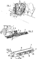
- Figure 1 is a schematic perspective view of a spraying apparatus equipped with devices according to the invention for creating air currents in the form of a vertical sheet.
- Figure 2 is a view similar to Figure 1 but with a device according to the invention, installed to produce an air flow in the form of a horizontal sheet.
- Figure 3 is a schematic perspective view of a unit blowing panel according to the invention.
- Figure 4 is a plan view, partially in section along the plane IV-IV of Figure 3, of a fan panel.
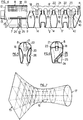
- Figures 5 and 6 are cross sections along lines V-V and VI-VI of Figure 4.
- Figure 7 is a perspective diagram showing the shape of a diffuser.
- Figure 8 is a view similar to Figure 3, of a variant.
- Figure 9 is an enlarged partial view of the section of Figure 4, with another device for spraying treatment liquid.
- FIG. 1 shows a tractor 1 which carries two projection ramps 2 arranged vertically to the left and to the right, supported by a gantry 3, a centrifugal compressor 4 mounted at the rear of the tractor, and conduits 5 connecting the compressor to each of the ramps.
- FIG. 2 shows a projection ramp 2 mounted horizontally on a trailer 6 coupled to the tractor 1 and provided with a gantry 3.
- the centrifugal compressor 4 is also mounted on the trailer, and it is connected to the ramp by conduits 5.
- ramps may be fine other arrangements and orientations, vertical, horizontal or oblique, depending on the problems raised.
- Each ramp 2 is made up of a number of aligned fan panels 7, which will now be described in more detail with the aid of FIGS. 3 to 6.
- Each panel 7 has the shape of an elongated and flattened box, with a first edge or inlet edge, 8, in the shape of a half-cylinder, an opposite edge, or projection edge, 9, thinner, and edges right and left 11, 12 substantially planes and converging towards the thin edge 9, the assembly somewhat evoking a portion of an aircraft wing.
- the panel 7 constitutes a sealed box, provided at one of its ends with a cylindrical end piece 13, which makes it possible to connect it in a sealed manner to a neighboring box, or to an inlet of compressed air, and at the same time to modify its orientation by pivoting around the axis of the end piece 13. If several panels are placed in series, a end piece 13 is provided at each end of the intermediate panels.
- a long box can be made by assembling standardized sections. You can form in very long pieces, then cut them to form sections of the desired length.
- the diameter of the passage increases from the neck to the projection edge.
- the passages 14 may not be parallel but converge towards a point situated in front, in the direction of the air movement, for a more concentrated action at a distance from the device. They can also diverge, starting from a point located behind, in the direction of the air movement, for a wider action.
- the outlet part 17 can also have a rectangular or flattened shape, for example for reasons of robustness or ease of construction, or to obtain a particular structure of the air jets.
- This surface is normally a plane, but in special cases, for example to treat shrubs having a particular shape, it is conceivable that it has another shape.
- the intake portion 15 of the passages 14 opens into an intake chamber 18 connected to the outside by a screen 19 which constitutes the intake edge 8.
- the part of the interior volume of the box 7 which is not occupied by the passages 14 or the intake chamber 18 constitutes a main manifold, filled with compressed air during the operation of the device.
- Injectors 20 are placed so as to be coaxial with the passages 14. They are located in the intake portion 15 of each passage 14, and directed towards the neck 16.
- the injectors 20 are connected to the main manifold, which supplies them with compressed air, by means of an auxiliary manifold 21 placed in the intake chamber 18.
- the auxiliary manifold 21 extends over almost the entire length of the intake chamber. It is connected to each injector 20 by a rectilinear conduit 22, coaxial with the passage 14, and other rectilinear conduits 23 parallel to the first conduits 22 connect the auxiliary collector to the main collector.
- the conduits 23 are arranged between two adjacent passages 14. As shown in Figure 4, this gives a very rigid, robust symmetrical structure and a regularly distributed power supply. However, other modes of execution can be provided.
- each injector can be connected directly to the main manifold by a tube bent at 180 °.
- nozzles 24 for a liquid treatment product are of the type which produces a flattened sheet of liquid droplets, this sheet being V-shaped, the top of which is located on the nozzle.
- the nozzles 24 are located in the plane which contains the axes of the passages 14, and the nozzles are arranged so as to produce a sheet of droplets which is essentially in the same plane.
- a nozzle is provided by two passages 14. It has been observed that a homogeneous distribution of the product is obtained, at a short distance from the box 7 treatment in the air stream obtained with all of the diffusers 14 of the box, operating together. It is however possible to provide a different arrangement of the nozzles, for example nozzles placed alternately with the outlets 17 of the diffusers, or in two lines situated on each side of the line of the outlets 17.
- the nozzles 24 are placed in cavities 25 provided in one of the right or left edges 11, 12 of the box 7.
- the same edge has a groove 26 perpendicular to the direction of the passages 14, and in which is housed a supply duct 27 sprinklers in treatment product.
- the nozzles 24 are thus easy to access, while being protected from shocks.
- the nozzles are of the rotating disc type described in document FR-A-2,497,439 in the name of the applicant. These nozzles produce a sheet of droplets projected by centrifugal force into an angular sector of the plane of the rotating disc.
- the disc is arranged so as to produce a sheet of droplets roughly tangent to the air sheet at the outlet of the diffusers.
- the nozzles are rotating discs whose plane is perpendicular to the direction of air flow. In the case of a rotating disc nozzle, it will preferably be placed beyond the cavity 25 in the direction of the air flow, or even in this flow itself.
- the groove 26 In the vicinity of the end of the box, the groove 26 is interrupted, and the conduit 27 penetrates inside the box to cross the junction plane between two adjacent boxes. The conduit 27 is thus protected in the region of the junction.
- FIG. 9 there is provided a device for spraying liquid of the type described in French patent application 94.07659, not published at the time of filing of this application.
- a "bursting piece" 28 which has a rounded edge facing upstream from the gas flow and a sharply angled edge directed opposite, and a means 29 for supplying treatment liquid capable of creating, on at least part of the bursting piece, a coating of substantially continuous treatment liquid .
- the supply means 29 is a tube which is connected to the conduit 27 and has suitably arranged orifices.
- the tube 29 crosses the wall of the passage 14, it is mounted as an extension of the conduit 27, which is then entirely inside the box, and there is neither cavity 25 nor groove 26.
- Other embodiments are possible, in accordance with the aforementioned French patent application 94.07659, which is incorporated into the present application for reference.
- the intake edge 8 is not constituted by a screen, but by a solid sheet in which are arranged small axial fans 30 arranged to send air into the chamber.
- the arrangement and the number of fans 30 are, of course, to be adapted to the problem posed and to the shape of the device.
- the drive motors 31 of the fans 30 can be electric or hydraulic motors.
- the fans can also be driven by a drive shaft connected to a common motor, which can be that of the carrier vehicle.
- the blower panel 7 is shown as a single piece, of relatively large dimensions.
- the current technique makes it possible to make such parts without major difficulties.
- the modular structure of the device allows its dimensions to be quickly adapted to requirements. However, if it is desired to temporarily change the number of passages 14 in activity, it is advantageous to provide shutters of calculated form for closing at least one injector, while being held in place by the converging part of the corresponding passage.
- FIG 4 there is shown in Figure 4, in broken lines, such a shutter 40 consisting of a mass 41 of deformable plastic which closes the injector 20 while being held by the convergent of the Venturi.
- a handle 42 is used for fitting and removing the shutter.
- the mass 41 also closes the passage 14, which is advantageous but not essential.
Landscapes
- Life Sciences & Earth Sciences (AREA)
- Engineering & Computer Science (AREA)
- Insects & Arthropods (AREA)
- Pest Control & Pesticides (AREA)
- Wood Science & Technology (AREA)
- Zoology (AREA)
- Environmental Sciences (AREA)
- Mechanical Engineering (AREA)
- General Engineering & Computer Science (AREA)
- Nozzles (AREA)
- Structures Of Non-Positive Displacement Pumps (AREA)
- Jet Pumps And Other Pumps (AREA)
Abstract
Description
La présente invention est relative à un dispositif apte à produire un courant d'air ayant en section transversale une forme aplatie, notamment pour projeter un produit de traitement sur le sol ou sur des végétaux.The present invention relates to a device capable of producing a stream of air having a flattened shape in cross section, in particular for spraying a treatment product on the ground or on plants.
Pour envoyer un courant d'air chargé de produit de traitement vers le sol ou vers des végétaux, on utilise habituellement deux types d'appareillages. Un premier type (brevets US-A-3 252 656 GREENWOOD, US-A-3 653 130 PATRICK, FR-A-1 314 453 BERTHOUD) comprend un ventilateur hélicoïdal qui projette un jet d'air à grand débit et vitesse modérée dans la direction de l'axe de rotation de son hélice. Ce jet d'air peut être dévié à l'aide de déflecteurs appropriés pour être transformé en un courant d'air à section transversale aplatie, mais, si on désire créer une nappe d'air en déplacement parallèle, de grande largeur, il est nécessaire de prévoir plusieurs ventilateurs ayant chacun ses déflecteurs.To send a stream of air laden with treatment product to the ground or to plants, two types of apparatus are usually used. A first type (US-A-3 252 656 GREENWOOD, US-A-3 653 130 PATRICK, FR-A-1 314 453 BERTHOUD patents) includes a axial fan which projects a jet of air at high speed and moderate speed. the direction of the axis of rotation of its propeller. This air jet can be deflected using suitable deflectors to be transformed into an air stream with a flattened cross section, but, if it is desired to create an air sheet in parallel movement, of large width, it is it is necessary to provide several fans each having its deflectors.
Un deuxième type d'appareillage (brevets US-A-4 026 469 FRANKEL, US-A-2 925 222 SPRENG) pour produire un courant d'air comprend un compresseur centrifuge unique, qui débite de l'air à débit modéré, sous une pression relativement élevée. L'air ainsi comprimé est acheminé par des conduits convenables jusqu'à des buses qui produisent des jets d'air à grande vitesse et faible section initiale. Les jets d'air produits, qui peuvent être de forme aplatie en section transversale, et qui peuvent être disposés tous dans un même plan, pénètrent dans l'air, et aussi dans le feuillage des végétaux, à la façon de poignards, c'est-à-dire que l'air se déplace à grande vitesse dans l'axe de chaque jet, mais cet air a une vitesse quasi-nulle entre les jets. Il en résulte une mauvaise répartition du produit de traitement.A second type of apparatus (patents US-A-4,026,469 KAISER + KRAFT, US-A-2,925,222 SPRENG) for producing an air stream comprises a single centrifugal compressor, which delivers air at moderate rate, under relatively high pressure. The air thus compressed is conveyed by suitable conduits to nozzles which produce jets of air at high speed and low initial section. The air jets produced, which can be flattened in cross section, and which can all be arranged in the same plane, penetrate into the air, and also into the foliage of plants, like daggers, it that is to say that the air moves at high speed in the axis of each jet, but this air has an almost zero speed between the jets. This results in a poor distribution of the treatment product.
Dans le document US-A-3 164 324, BRUINSMA, on a décrit un appareil qui contient à la fois un compresseur centrifuge et des ventilateurs hélicoïdaux. Le compresseur centrifuge sert seulement à produire un jet d'air à grande vitesse qui sert à déchiqueter un jet de liquide de traitement en fines gouttelettes, qui sont injectées, à l'aide du même jet d'air à grande vitesse, selon l'axe du courant d'air créé par le ventilateur hélicoïde. Cette solution compliquée ne permet pas d'échapper aux inconvénients des appareillages à ventilateurs hélicoïdes.In US-A-3,164,324, BRUINSMA, an apparatus has been described which contains both a centrifugal compressor and helical fans. The centrifugal compressor is only used to produce a high speed air jet which is used to shred a liquid jet from treatment in fine droplets, which are injected, using the same air jet at high speed, along the axis of the air current created by the helical fan. This complicated solution does not make it possible to escape the drawbacks of equipment with axial fans.
Le document GB-A-2.227.399 fait appel à une autre technique, qui est celle du venturi. Selon cette technique, un jet d'air à grande vitesse est injecté, par injecteur formé d'une buse ou analogue, axialement à l'entrée d'un diffuseur formé d'un conduit convergent-divergent. Le jet d'air communique son énergie à l'air qui se trouve dans le diffuseur, si bien qu'on peut obtenir un écoulement d'air à grand débit et vitesse modérée, analogue à celui que fournit un ventilateur hélicoïdal.The document GB-A-2.227.399 uses another technique, which is that of the venturi. According to this technique, a high speed air jet is injected, by injector formed by a nozzle or the like, axially at the inlet of a diffuser formed by a convergent-divergent duct. The jet of air communicates its energy with the air which is in the diffuser, so that one can obtain a flow of air with great flow and moderate speed, analogous to that which provides a helical fan.
Pour obtenir un courant d'air de forme aplatie, il est prévu, selon le document qu'on vient de citer, d'utiliser soit un diffuseur unique, rectiligne en section transversale, et de grande longueur, alimenté par une série d'injecteurs montés sur un collecteur parallèle au diffuseur, soit une série d'ensembles injecteur-diffuseur, dans lesquels chaque diffuseur est à section fermée, ovale ou circulaire, et associé à un injecteur unique, relié au collecteur par un conduit.To obtain a flattened air current, according to the document just cited, it is intended to use either a single diffuser, rectilinear in cross section, and of great length, supplied by a series of injectors mounted on a manifold parallel to the diffuser, ie a series of injector-diffuser assemblies, in which each diffuser is of closed section, oval or circular, and associated with a single injector, connected to the collector by a conduit.
La première solution est connue pour ne donner de bons résultats que dans une gamme de débits étroite, et la seconde solution aboutit à une structure complexe et lourde, et à un montage compliqué.The first solution is known to give good results only in a narrow range of flow rates, and the second solution results in a complex and heavy structure, and in a complicated assembly.
La présente invention a pour but de fournir un dispositif qui procure les performances d'un système à plusieurs ensembles comprenant chacun un diffuseur à section fermée associée à un injecteur unique, et qui puisse en même temps être construit de façon simple et peu coûteuse.The object of the present invention is to provide a device which provides the performance of a system with several assemblies each comprising a closed section diffuser associated with a single injector, and which can at the same time be constructed in a simple and inexpensive manner.
Pour obtenir ce résultat, l'invention fournit un dispositif pour produire un courant d'air ayant une forme aplatie en section transversale, ce dispositif comprenant:
- au moins deux diffuseurs, formés chacun d'un conduit convergent-divergent ouvert à ses deux extrémités, ces diffuseurs étant placés dans le plan de la plus grande dimension de la section transversale du courant d'air qu'on désire obtenir, et
- un injecteur associé à chaque diffuseur, à peu près coaxial au conduit formant le diffuseur, et situé dans sa partie convergente en étant dirigé vers la partie divergente, ledit injecteur étant relié par des moyens d'amenée d'air comprimé à un compresseur centrifuge de telle façon que l'air comprimé produit par le compresseur et projeté par l'injecteur met en mouvement, ou accélère, l'air se trouvant dans le diffuseur par effet Venturi,
dispositif qui comprend un caisson qui peut être alimenté en air comprimé par le compresseur centrifuge et constitue un collecteur, ce caisson étant traversé de façon étanche par des passages séparés, situés dans le plan de la plus grande dimension de la section transversale du jet d'air à produire, ces passages étant de forme convergente-divergente et constituant les diffuseurs, et les injecteurs étant placés à l'intérieur des passages et étant reliés à l'intérieur du caisson par des conduits d'alimentation.To obtain this result, the invention provides a device for producing an air stream having a flattened shape in cross section, this device comprising:
- at least two diffusers, each formed of a convergent-divergent duct open at its two ends, these diffusers being placed in the plane of the largest dimension of the cross section of the air stream that it is desired to obtain, and
- an injector associated with each diffuser, roughly coaxial with the duct forming the diffuser, and located in its converging part while being directed towards the diverging part, said injector being connected by means of compressed air supply to a centrifugal compressor of such that the compressed air produced by the compressor and projected by the injector sets in motion, or accelerates, the air in the diffuser by the Venturi effect,
device which comprises a box which can be supplied with compressed air by the centrifugal compressor and constitutes a collector, this box being crossed in leaktight manner by separate passages, situated in the plane of the largest dimension of the cross section of the jet of air to be produced, these passages being of convergent-divergent form and constituting the diffusers, and the injectors being placed inside the passages and being connected to the interior of the box by supply conduits.
La structure en caisson procure, comme il est connu, une grande rigidité pour un poids très inférieur à celui de structures plus complexes de même rigidité. La forme particulière du caisson traversé par des passages peut être obtenue, sans difficulté particulière, par les techniques actuelles de moulage-soufflage sous pression de matières plastiques.The box structure provides, as is known, great rigidity for a weight much lower than that of more complex structures of the same rigidity. The particular shape of the box through which passages can be obtained, without particular difficulty, by the current blow-molding techniques under pressure of plastic materials.
Avantageusement, les conduits d'alimentation des injecteurs comprennent un collecteur auxiliaire, qui alimente chacun des injecteurs par un conduit relié, par d'autres conduits, à l'intérieur du caisson qui forme un collecteur principal.Advantageously, the supply conduits for the injectors comprise an auxiliary collector, which supplies each of the injectors by a conduit connected, by other conduits, inside the box which forms a main collector.
L'ensemble du dispositif est ainsi composé par assemblage de deux pièces de grandes dimensions mais d'obtention facile, le caisson et le collecteur, et de pièces annexes de faible coût telles que les conduits précités.The entire device is thus composed by assembling two parts of large dimensions but easy to obtain, the box and the collector, and of low-cost annex parts such as the aforementioned conduits.
Dans le cas d'un dispositif comportant des moyens de pulvérisation de produit de traitement, disposés à proximité des sorties des diffuseurs, dans le sens de déplacement de l'air, il est avantageux de prévoir que ces moyens sont également portés par le caisson. Avantageusement, ces moyens sont des gicleurs placés dans des cavités du caisson.In the case of a device comprising means for spraying treatment product, disposed near the outputs of the diffusers, in the direction of movement of the air, it is advantageous to provide that these means are also carried by the box. Advantageously, these means are sprinklers placed in cavities of the box.
Suivant une réalisation plus avantageuse encore, les moyens de pulvérisation comprennent une pièce d'éclatement qui a un bord arrondi tourné vers l'amont de l'écoulement gazeux et une arête à angle vif dirigée à l'opposé, et un moyen d'alimentation en liquide de traitement apte à créer, sur au moins une partie de la pièce d'éclatement, un revêtement sensiblement continu dudit liquide, la pièce d'éclatement et le moyen d'alimentation étant placés dans la région de la sortie de l'injecteur et du col du convergent-divergent formé par le passage.According to an even more advantageous embodiment, the spraying means comprise a bursting part which has a rounded edge turned upstream of the gas flow and a sharp angle edge directed opposite, and a supply means in treatment liquid capable of creating, on at least part of the bursting piece, a substantially continuous coating of said liquid, the bursting piece and the supply means being placed in the region of the outlet of the injector and of the neck of the convergent-divergent formed by the passage.
Dans le cas qu'on vient d'évoquer, et si les moyens de pulvérisation sont reliés séparément à un conduit d'alimentation commun, pour une meilleure protection, il est encore avantageux de prévoir que ce conduit est logé au moins en partie dans une rainure du caisson, et/ou que ce conduit passe au moins en partie à l'intérieur du caisson et/ou d'un conduit d'amenée d'air comprimé dans le caisson.In the case just mentioned, and if the spraying means are connected separately to a common supply duct, for better protection, it is still advantageous to provide that this duct is housed at least partly in a groove of the box, and / or that this duct passes at least partially inside the box and / or of a compressed air supply pipe in the box.
Ces structures mettent à profit la rigidité du caisson pour un maximum d'allégement et de simplification de l'ensemble sans compliquer exagérément la fabrication du caisson.These structures take advantage of the rigidity of the box for maximum lightening and simplification of the assembly without excessively complicating the manufacture of the box.
Si le dispositif est placé dans un appareillage fixe, l'air dans le diffuseur est immobile quand l'injecteur n'est pas en action. Si le dispositif est monté sur un véhicule, l'air dans le diffuseur peut se déplacer à faible vitesse en fonction de la vitesse du véhicule, du vent, et de l'orientation du diffuseur. Cette vitesse est habituellement relativement faible.If the device is placed in a fixed apparatus, the air in the diffuser is stationary when the injector is not in action. If the device is mounted on a vehicle, the air in the diffuser can move at low speed depending on the speed of the vehicle, the wind, and the orientation of the diffuser. This speed is usually relatively low.
Suivant un mode de réalisation intéressant pour réaliser des courants d'air puissants, un ventilateur hélicoïde est associé au diffuseur de façon à créer dans celui-ci un écoulement d'air qui sera accéléré par l'effet Venturi quand l'injecteur sera en action. On crée ainsi un effet de "gavage".According to an advantageous embodiment for producing strong air currents, a helical fan is associated with the diffuser so as to create in this an air flow which will be accelerated by the Venturi effect when the injector is in action. This creates a "force-feeding" effect.
L'invention va maintenant être décrite de façon plus détaillée à l'aide d'un exemple pratique illustré à l'aide des dessins parmi lesquels :The invention will now be described in more detail with the aid of a practical example illustrated with the aid of the drawings among which:
La figure 1 est une vue perspective schématique d'un appareillage de pulvérisation équipé de dispositifs selon l'invention pour créer des courants d'air en forme de nappe verticale.Figure 1 is a schematic perspective view of a spraying apparatus equipped with devices according to the invention for creating air currents in the form of a vertical sheet.
La figure 2 est une vue analogue à la figure 1 mais avec un dispositif conforme à l'invention, installé pour produire un courant d'air en forme de nappe horizontale.Figure 2 is a view similar to Figure 1 but with a device according to the invention, installed to produce an air flow in the form of a horizontal sheet.
La figure 3 est une vue perspective schématique d'un panneau soufflant unitaire conforme à l'invention.Figure 3 is a schematic perspective view of a unit blowing panel according to the invention.
La figure 4 est une vue en plan, partiellement en coupe selon le plan IV-IV de la figure 3, d'un panneau soufflant.Figure 4 is a plan view, partially in section along the plane IV-IV of Figure 3, of a fan panel.
Les figures 5 et 6 sont des coupes transversales selon les lignes V-V et VI-VI de la figure 4.Figures 5 and 6 are cross sections along lines V-V and VI-VI of Figure 4.
La figure 7 est un schéma en perspective montrant la forme d'un diffuseur.Figure 7 is a perspective diagram showing the shape of a diffuser.
La figure 8 est une vue analogue à la figure 3, d'une variante.Figure 8 is a view similar to Figure 3, of a variant.
La figure 9 est une vue partielle agrandie de la coupe de la figure 4, avec un autre dispositif de pulvérisation de liquide de traitement.Figure 9 is an enlarged partial view of the section of Figure 4, with another device for spraying treatment liquid.
La figure 1 montre un tracteur 1 qui porte deux rampes de projection 2 disposées verticalement à gauche et à droite, supportées par un portique 3, un compresseur centrifuge 4 monté à l'arrière du tracteur, et des conduits 5 reliant le compresseur à chacune des rampes.FIG. 1 shows a tractor 1 which carries two
La figure 2 montre une rampe de projection 2 montée horizontalement sur une remorque 6 attelée au tracteur 1 et pourvue d'un portique 3. Le compresseur centrifuge 4 est également monté sur la remorque, et il est relié à la rampe par des conduits 5.FIG. 2 shows a
On notera que les figures 1 et 2 ne donnent que des exemples non limitatifs. Les rampes peuvent avoir bien d'autres dispositions et orientations, verticales, horizontales ou obliques, selon les problèmes posés.Note that Figures 1 and 2 give only non-limiting examples. The ramps may be fine other arrangements and orientations, vertical, horizontal or oblique, depending on the problems raised.
Chaque rampe 2 est constituée d'un certain nombre de panneaux soufflants 7, alignés, qu'on va maintenant décrire plus en détail à l'aide des figures 3 à 6.Each
Chaque panneau 7 a la forme d'un caisson allongé et aplati, avec un premier bord ou bord d'admission, 8, en forme de demi-cylindre, un bord opposé, ou bord de projection, 9, plus mince, et des bords droit et gauche 11, 12 sensiblement plans et convergeant vers le bord mince 9, l'ensemble évoquant un peu une partie d'aile d'avion.Each
On notera que les dénominations "droit" et "gauche" sont purement arbitraires : Si la rampe de projection est verticale et perpendiculaire au sens de la marche, comme dans la figure 1, un des bords droit ou gauche est en avant dans le sens de la marche du tracteur, et l'autre est en arrière. Si la rampe de projection est horizontale, comme dans la figure 2, un des bords droit ou gauche est situé au-dessus, et l'autre au-dessous.Note that the denominations "right" and "left" are purely arbitrary: If the projection ramp is vertical and perpendicular to the direction of travel, as in Figure 1, one of the right or left edges is forward in the direction of the tractor walking, and the other is back. If the projection ramp is horizontal, as in figure 2, one of the right or left edges is located above, and the other below.
Le panneau 7 constitue un caisson étanche, pourvu à une de ses extrémités d'un embout cylindrique 13, qui permet de le raccorder de façon étanche à un caisson voisin, ou à une arrivée d'air comprimé, et en même temps de modifier son orientation par pivotement autour de l'axe de l'embout 13. Si plusieurs panneaux sont placés en série, un embout 13 est prévu à chacune des extrémités des panneaux intermédiaires.The
Suivant un mode de réalisation préféré, il n'y a pas d'embout 13 à proprement parler, mais les extrémités de deux caissons successifs sont ouvertes et liées l'une à l'autre à l'aide de manchons, ou plutôt en prévoyant qu'elles ont une section de taille légèrement différente si bien que l'extrémité la plus petite est enfoncée, avec étanchéité, dans l'autre. A la figure 8, on a représenté un caisson ayant une extrémité élargie 13A, mais une disposition différente est possible. Bien entendu, le mode de liaison est indépendant du dispositif de gavage également montré à la figure 8 et décrit plus loin.According to a preferred embodiment, there is no
Une telle réalisation permet des fabrications simplifiées. Par exemple, on peut constituer un caisson de grande longueur par assemblage de tronçons standardisés. On peut former dans des pièces de grande longueur, puis les couper pour former des tronçons de la longueur désirée.Such an embodiment allows simplified manufacturing. For example, a long box can be made by assembling standardized sections. You can form in very long pieces, then cut them to form sections of the desired length.
Un certain nombre de passages 14, parallèles entre eux, débouchent sur le bord de projection 9. Ils présentent une forme convergente-divergente. Comme le montre la figure 7, leur section transversale varie progressivement d'une forme rectangulaire à leur partie d'admission 15 à une forme circulaire au niveau de leur col 16 où l'aire de la section est minimale. La partie de sortie 17, qui rejoint le bord de projection 9, a une section transversale de forme circulaire. Le diamètre du passage augmente depuis le col jusqu'au bord de projection. Une telle forme permet par comparaison avec une forme circulaire d'un bout à l'autre, d'augmenter la section d'admission sans changer l'écart entre passages voisins.A number of
La disposition et/ou la forme des passages peuvent être différentes de celle qui est décrite, en fonction de la nature des problèmes posés. En particulier, les passages 14 peuvent ne pas être parallèles mais converger vers un point situé en avant, dans le sens du déplacement d'air, pour une action plus concentrée à distance du dispositif. Ils peuvent aussi diverger, à partir d'un point situé en arrière, dans le sens du déplacement d'air, pour une action plus élargie. D'autre part, la partie de sortie 17 peut aussi avoir une forme rectangulaire ou aplatie, par exemple pour des raisons de robustesse ou de facilité de construction, ou pour obtenir une structure particulière des jets d'air.The arrangement and / or the shape of the passages may be different from that described, depending on the nature of the problems raised. In particular, the
Il est important que les axes des jets d'air constituent ensemble une surface continue. Cette surface est normalement un plan, mais dans des cas particuliers, par exemple pour traiter des arbustes ayant une forme particulière, on peut concevoir qu'elle ait une autre forme.It is important that the axes of the air jets together form a continuous surface. This surface is normally a plane, but in special cases, for example to treat shrubs having a particular shape, it is conceivable that it has another shape.
La partie d'admission 15 des passages 14 débouche dans une chambre d'admission 18 reliée à l'extérieur par un grillage 19 qui constitue le bord d'admission 8.The
La partie du volume intérieur du caisson 7 qui n'est pas occupée par les passages 14 ou la chambre d'admission 18 constitue un collecteur principal, rempli d'air comprimé pendant le fonctionnement du dispositif.The part of the interior volume of the
Des injecteurs 20 sont placés de façon à être coaxiaux aux passages 14. Ils sont situés dans la partie d'admission 15 de chaque passage 14, et dirigés vers le col 16.
Les injecteurs 20 sont reliés au collecteur principal, qui les alimente en air comprimé, par l'intermédiaire d'un collecteur auxiliaire 21 placé dans la chambre d'admission 18.The
Le collecteur auxiliaire 21 s'étend sur à peu près toute la longueur de la chambre d'admission. Il est relié à chaque injecteur 20 par un conduit rectiligne 22, coaxial au passage 14, et d'autres conduits rectilignes 23 parallèles aux premiers conduits 22 relient le collecteur auxiliaire au collecteur principal. Les conduits 23 sont disposés entre deux passages 14 adjacents. Comme le montre la figure 4, on obtient ainsi une structure symétrique très rigide, robuste et une alimentation régulièrement répartie. On peut toutefois prévoir d'autres modes d'exécution. Par exemple, chaque injecteur peut être relié directement au collecteur principal par un tube coudé à 180°.The
A proximité du bord de projection 9 du caisson 7 sont placés des gicleurs 24 pour un produit de traitement liquide. Ces gicleurs sont du type qui produit une nappe aplatie de gouttelettes de liquide, cette nappe étant en forme de V dont le sommet se trouve sur le gicleur. Les gicleurs 24 sont situés dans le plan qui contient les axes des passages 14, et les gicleurs sont disposés de façon à produire une nappe de gouttelettes qui est essentiellement dans le même plan. Il est prévu un gicleur par deux passages 14. On a constaté qu'on obtient, à faible distance du caisson 7, une répartition homogène du produit de traitement dans le courant d'air obtenu avec l'ensemble des diffuseurs 14 du caisson, fonctionnant ensemble. Il est cependant possible de prévoir une disposition différente des gicleurs, par exemple des gicleurs placés en alternance avec les sorties 17 des diffuseurs, ou en deux lignes situées de chaque côté de la ligne des sorties 17.Near the
Les gicleurs 24 sont placés dans des cavités 25 prévues dans un des bords droit ou gauche 11, 12 du caisson 7. Le même bord présente une rainure 26 perpendiculaire à la direction des passages 14, et dans laquelle est logé un conduit 27 d'alimentation des gicleurs en produit de traitement. Les gicleurs 24 sont ainsi d'accès facile, tout en étant protégés des chocs.The
Dans une variante, les gicleurs sont du type à disque tournant décrit dans le document FR-A-2.497.439 au nom de la demanderesse. Ces gicleurs produisent une nappe de gouttelettes projetées par la force centrifuge dans un secteur angulaire du plan du disque tournant. Ici le disque est disposé de façon à produire une nappe de gouttelettes à peu près tangente à la nappe d'air à la sortie des diffuseurs.In a variant, the nozzles are of the rotating disc type described in document FR-A-2,497,439 in the name of the applicant. These nozzles produce a sheet of droplets projected by centrifugal force into an angular sector of the plane of the rotating disc. Here the disc is arranged so as to produce a sheet of droplets roughly tangent to the air sheet at the outlet of the diffusers.
Dans une autre variante, les gicleurs sont des disques tournants dont le plan est perpendiculaire à la direction d'écoulement d'air. Dans le cas d'un gicleur à disque tournant, il sera placé de préférence au-delà de la cavité 25 dans le sens de l'écoulement d'air, ou même dans cet écoulement lui-même.In another variant, the nozzles are rotating discs whose plane is perpendicular to the direction of air flow. In the case of a rotating disc nozzle, it will preferably be placed beyond the
Au voisinage de l'extrémité du caisson, la rainure 26 s'interrompt, et le conduit 27 pénètre à l'intérieur du caisson pour traverser le plan de jonction entre deux caissons adjacents. Le conduit 27 est ainsi protégé dans la zone de la jonction.In the vicinity of the end of the box, the
Dans une autre variante intéressante, illustré à la figure 9, on prévoit un dispositif de pulvérisation de liquide du type décrit dans la demande de brevet français 94.07659, non publiée au moment du dépôt de la présente demande.In another interesting variant, illustrated in FIG. 9, there is provided a device for spraying liquid of the type described in French patent application 94.07659, not published at the time of filing of this application.
Plus précisément, il est prévu, dans la région de la sortie 17 de l'injecteur 20 et du col 16 du Venturi formé par le passage 14, une "pièce d'éclatement" 28 qui a un bord arrondi tourné vers l'amont de l'écoulement gazeux et une arête à angle vif dirigée à l'opposé, et un moyen 29 d'alimentation en liquide de traitement apte à créer, sur au moins une partie de la pièce d'éclatement un revêtement de liquide de traitement sensiblement continu.More specifically, there is provided, in the region of the
Dans l'exemple décrit à la figure 9, le moyen d'alimentation 29 est un tube qui est relié au conduit 27 et présente des orifices convenablement disposés. Le tube 29 traverse la paroi du passage 14, il est monté en prolongement du conduit 27, qui est alors entièrement à l'intérieur du caisson, et il n'y a ni cavité 25 ni rainure 26. D'autres réalisations sont possibles, conformément à la demande de brevet français 94.07659 précitée, qui est incorporée à la présente demande à titre de référence.In the example described in Figure 9, the supply means 29 is a tube which is connected to the
Dans une variante illustrée à la figure 8, le bord d'admission 8 n'est pas constitué par un grillage, mais par une tôle pleine dans laquelle sont disposés de petits ventilateurs hélicoïdes 30 disposés pour envoyer de l'air dans la chambre d'admission 18, et créer dans la partie d'admission 15 des passages 14 un courant d'air qui sera accéléré par effet Venturi sous l'action du jet d'air produit par l'injecteur 20. On obtient ainsi un effet de "gavage" qui améliore sensiblement le rendement des ensembles diffuseur-injecteur.In a variant illustrated in FIG. 8, the
La disposition et le nombre des ventilateurs 30 sont, bien entendu, à adapter au problème posé et à la forme du dispositif. Les moteurs d'entraînement 31 des ventilateurs 30 peuvent être des moteurs électriques ou hydrauliques. Les ventilateurs peuvent également être entraînés par un arbre de transmission relié à un moteur commun, qui peut être celui du véhicule porteur.The arrangement and the number of
Sur les dessins, on a représenté le panneau soufflant 7 comme d'une seule pièce, d'assez grandes dimensions. La technique actuelle permet de faire de telles pièces sans difficultés majeures. Toutefois, il peut être préférable de constituer le panneau soufflant par assemblage d'éléments unitaires, de préférence identiques, correspondant chacun à un seul passage 14 ou à un petit nombre de passages. On peut ainsi facilement adapter en usine la dimension du panneau soufflant à la demande.In the drawings, the
La structure modulaire du dispositif permet d'adapter rapidement ses dimensions aux besoins. Toutefois, au cas où on désire momentanément modifier le nombre de passages 14 en activité, il est avantageux de prévoir des obturateurs de forme calculée pour obturer au moins un injecteur, en étant maintenus en place par la partie convergente du passage correspondant.The modular structure of the device allows its dimensions to be quickly adapted to requirements. However, if it is desired to temporarily change the number of
On a représenté à la figure 4, en tirets, un tel obturateur 40 constitué d'une masse 41 de matière plastique déformable qui vient obturer l'injecteur 20 en étant maintenu par le convergent du Venturi. Une poignée 42 sert à la mise en place et à l'enlèvement de l'obturateur. Dans le cas représenté sur la figure, la masse 41 obture également le passage 14, ce qui est avantageux mais non indispensable.There is shown in Figure 4, in broken lines, such a
Claims (12)
Applications Claiming Priority (2)
| Application Number | Priority Date | Filing Date | Title |
|---|---|---|---|
| FR9313437 | 1993-11-10 | ||
| FR9313437A FR2712354B1 (en) | 1993-11-10 | 1993-11-10 | Device for producing an air stream having a flattened shape in cross section. |
Publications (2)
| Publication Number | Publication Date |
|---|---|
| EP0653157A1 true EP0653157A1 (en) | 1995-05-17 |
| EP0653157B1 EP0653157B1 (en) | 1999-03-17 |
Family
ID=9452738
Family Applications (1)
| Application Number | Title | Priority Date | Filing Date |
|---|---|---|---|
| EP94402524A Expired - Lifetime EP0653157B1 (en) | 1993-11-10 | 1994-11-08 | Device to produce an air flow having a flattened cross section |
Country Status (9)
| Country | Link |
|---|---|
| US (1) | US5586725A (en) |
| EP (1) | EP0653157B1 (en) |
| AU (1) | AU679569B2 (en) |
| BR (1) | BR9404395A (en) |
| DE (1) | DE69417151T2 (en) |
| DK (1) | DK0653157T3 (en) |
| ES (1) | ES2130376T3 (en) |
| FR (1) | FR2712354B1 (en) |
| ZA (1) | ZA948859B (en) |
Cited By (4)
| Publication number | Priority date | Publication date | Assignee | Title |
|---|---|---|---|---|
| WO2007043090A1 (en) * | 2005-10-11 | 2007-04-19 | Ivano Marcantoni | Vertical air conveyor for agricultural sprayer machines |
| EP2420138A1 (en) | 2010-08-17 | 2012-02-22 | Exel Industries | System for producing at least one air current with elongate cross section |
| CN105850954A (en) * | 2016-04-06 | 2016-08-17 | 华南农业大学 | Multi-atomization fluttering-preventing sprayer |
| WO2019122221A1 (en) | 2017-12-22 | 2019-06-27 | Institut National De Recherche En Sciences Et Technologies Pour L'environnement Et L'agriculture | System and method for spraying a product, notably a plant-protection product |
Families Citing this family (5)
| Publication number | Priority date | Publication date | Assignee | Title |
|---|---|---|---|---|
| US6257498B1 (en) | 1997-10-07 | 2001-07-10 | James R. Siebol | Method and apparatus for an agricultural air handler |
| US6338439B1 (en) * | 1999-12-22 | 2002-01-15 | Visteon Global Tech., Inc. | Nozzle assembly |
| FR2892893B1 (en) * | 2005-11-04 | 2007-12-28 | Gerard Balespouey | SPRAYER OF TREATMENT PRODUCTS ON CROPS |
| DE102010017595A1 (en) * | 2010-06-25 | 2011-12-29 | Teddington Luftschleieranlagen Gmbh | Device for producing an air curtain |
| WO2013090641A1 (en) * | 2011-12-13 | 2013-06-20 | Genz Corp. | Recapture sprayer |
Citations (6)
| Publication number | Priority date | Publication date | Assignee | Title |
|---|---|---|---|---|
| FR1314453A (en) * | 1961-11-27 | 1963-01-11 | P Berthoud Ets | Improvements to agricultural turbine sprayers |
| US3164324A (en) * | 1962-05-18 | 1965-01-05 | Kiekens Wervelwind Holland Kie | Spraying vehicle |
| US3252656A (en) * | 1963-11-20 | 1966-05-24 | Fmc Corp | Spray discharge head |
| US4026469A (en) * | 1974-02-27 | 1977-05-31 | The State Of Israel, Ministry Of Agriculture | Apparatus for spraying bushes and trees |
| JPH01257414A (en) * | 1987-12-14 | 1989-10-13 | Masuda Hideo | Diffuser for mixed gas |
| GB2227399A (en) * | 1989-01-25 | 1990-08-01 | Nat Res Dev | Spraying using high pressure air. |
Family Cites Families (11)
| Publication number | Priority date | Publication date | Assignee | Title |
|---|---|---|---|---|
| US2735719A (en) * | 1956-02-21 | Paint sprayer | ||
| US2925222A (en) * | 1957-01-30 | 1960-02-16 | F E Myers & Bro Co | Spraying machine |
| US3472454A (en) * | 1967-10-26 | 1969-10-14 | Subscription Television Inc | Low volume sprayer system |
| US3994437A (en) * | 1975-09-19 | 1976-11-30 | Albany International Corporation | Broadcast dissemination of trace quantities of biologically active chemicals |
| US4375954A (en) * | 1979-12-26 | 1983-03-08 | Roger Trudel | Oil and gas combination nozzle |
| US4634054A (en) * | 1983-04-22 | 1987-01-06 | Combustion Engineering, Inc. | Split nozzle tip for pulverized coal burner |
| US5176322A (en) * | 1986-08-29 | 1993-01-05 | Sartor Giuseppe M | Crop-spraying apparatus |
| DE3833983A1 (en) * | 1988-10-06 | 1990-04-12 | Gardena Kress & Kastner Gmbh | IRRIGATION DEVICE |
| US5305548A (en) * | 1992-11-12 | 1994-04-26 | Siebol James R | Orchard heat exchanger |
| US5307992A (en) * | 1992-11-18 | 1994-05-03 | Usbi Co. | Method and system for coating a substrate with a reinforced resin matrix |
| US5310116A (en) * | 1992-12-01 | 1994-05-10 | The Broyhill Company | Drift control enclosure for an agricultural sprayer |
-
1993
- 1993-11-10 FR FR9313437A patent/FR2712354B1/en not_active Expired - Fee Related
-
1994
- 1994-11-08 DE DE69417151T patent/DE69417151T2/en not_active Expired - Lifetime
- 1994-11-08 EP EP94402524A patent/EP0653157B1/en not_active Expired - Lifetime
- 1994-11-08 DK DK94402524T patent/DK0653157T3/en active
- 1994-11-08 ES ES94402524T patent/ES2130376T3/en not_active Expired - Lifetime
- 1994-11-09 US US08/338,738 patent/US5586725A/en not_active Expired - Lifetime
- 1994-11-09 BR BR9404395A patent/BR9404395A/en not_active IP Right Cessation
- 1994-11-09 ZA ZA948859A patent/ZA948859B/en unknown
- 1994-11-09 AU AU77709/94A patent/AU679569B2/en not_active Ceased
Patent Citations (6)
| Publication number | Priority date | Publication date | Assignee | Title |
|---|---|---|---|---|
| FR1314453A (en) * | 1961-11-27 | 1963-01-11 | P Berthoud Ets | Improvements to agricultural turbine sprayers |
| US3164324A (en) * | 1962-05-18 | 1965-01-05 | Kiekens Wervelwind Holland Kie | Spraying vehicle |
| US3252656A (en) * | 1963-11-20 | 1966-05-24 | Fmc Corp | Spray discharge head |
| US4026469A (en) * | 1974-02-27 | 1977-05-31 | The State Of Israel, Ministry Of Agriculture | Apparatus for spraying bushes and trees |
| JPH01257414A (en) * | 1987-12-14 | 1989-10-13 | Masuda Hideo | Diffuser for mixed gas |
| GB2227399A (en) * | 1989-01-25 | 1990-08-01 | Nat Res Dev | Spraying using high pressure air. |
Non-Patent Citations (1)
| Title |
|---|
| PATENT ABSTRACTS OF JAPAN vol. 14, no. 14 (C - 674) 12 January 1990 (1990-01-12) * |
Cited By (5)
| Publication number | Priority date | Publication date | Assignee | Title |
|---|---|---|---|---|
| WO2007043090A1 (en) * | 2005-10-11 | 2007-04-19 | Ivano Marcantoni | Vertical air conveyor for agricultural sprayer machines |
| EP2420138A1 (en) | 2010-08-17 | 2012-02-22 | Exel Industries | System for producing at least one air current with elongate cross section |
| CN105850954A (en) * | 2016-04-06 | 2016-08-17 | 华南农业大学 | Multi-atomization fluttering-preventing sprayer |
| WO2019122221A1 (en) | 2017-12-22 | 2019-06-27 | Institut National De Recherche En Sciences Et Technologies Pour L'environnement Et L'agriculture | System and method for spraying a product, notably a plant-protection product |
| US11882822B2 (en) | 2017-12-22 | 2024-01-30 | Institut National De Recherche Pour L'agriculture, L'alimentation Et L'environnement | System and method for spraying a product, in particular a plant-protection product |
Also Published As
| Publication number | Publication date |
|---|---|
| DE69417151T2 (en) | 1999-07-01 |
| AU7770994A (en) | 1995-05-18 |
| DE69417151D1 (en) | 1999-04-22 |
| DK0653157T3 (en) | 1999-10-11 |
| ZA948859B (en) | 1995-07-26 |
| FR2712354A1 (en) | 1995-05-19 |
| US5586725A (en) | 1996-12-24 |
| ES2130376T3 (en) | 1999-07-01 |
| FR2712354B1 (en) | 1996-01-05 |
| AU679569B2 (en) | 1997-07-03 |
| EP0653157B1 (en) | 1999-03-17 |
| BR9404395A (en) | 1995-06-20 |
Similar Documents
| Publication | Publication Date | Title |
|---|---|---|
| EP2271835B1 (en) | Device with secondary jets reducing the noise generated by an aircraft jet engine | |
| FR3037826B1 (en) | SPRAY UNIT, COMPACT SPRAY MODULE COMPRISING SUCH A UNIT AND SPRAY AND PILOTAGE SYSTEM COMPRISING A PLURALITY OF SUCH MODULES | |
| EP2257704B1 (en) | Device for reducing the noise generated by an aircraft jet engine with fluid jets of the same orientation | |
| EP2279341B1 (en) | Device for reducing noise generated by an aircraft jet engine with curved ducts | |
| CA1037443A (en) | Suction and wet dust eliminating means_ | |
| EP0653157B1 (en) | Device to produce an air flow having a flattened cross section | |
| EP2846115B1 (en) | Device for producing artificial snow, and method for producing artificial snow | |
| EP0999947A1 (en) | Motor vehicle ventilation device | |
| EP2441523B1 (en) | Device for spraying a treatment fluid and system for spraying a treatment fluid including at least one such device | |
| EP3726980B1 (en) | System and method for spraying a product, notably a plant-protection product | |
| EP3325792B1 (en) | Aircraft propulsion assembly comprising a thrust reverser | |
| EP0454548B1 (en) | Device for centrifugally spraying a coating material, more particularly for electrostatic spray coating | |
| CA1314914C (en) | Forced jet granular material spreader | |
| FR2795914A1 (en) | MECHANICAL COMPRESSED GAS TRIMMER | |
| EP0893047B1 (en) | Method and device for cutting vegetation | |
| FR2891474A1 (en) | Mist sprayer e.g. for cooling or disinfecting air in enclosed building has centrifugal fan to generate gas flow carrying liquid droplets | |
| EP0730498B1 (en) | Surface treatment nozzle and method and device for surface treatment using such a nozzle | |
| FR2668399A1 (en) | Spray device for treating vegetables, using a liquid sprayed into an air jet | |
| CA2253676C (en) | Process and device for cutting vegetation | |
| WO2023238083A1 (en) | Section of boom for spraying a product onto a plant target, spray boom and agricultural sprayer | |
| FR2641479A1 (en) | Method and device for delivering a treatment product to plants | |
| WO2004030828A1 (en) | Liquid spraying device and agricultural machinery equipped with at least one device | |
| EP0363282B1 (en) | Use of a nozzle having a convergent-divergent profile in an ejection device for a root-cutter | |
| FR2991013A1 (en) | Air guiding device for use in ventilator nozzle to support drive motor of ventilator propeller in cooling module of car, has deflector for modifying direction of air at exit of propeller to direct air toward radial direction | |
| FR2779073A1 (en) | Apparatus for liquid spraying of plants |
Legal Events
| Date | Code | Title | Description |
|---|---|---|---|
| PUAI | Public reference made under article 153(3) epc to a published international application that has entered the european phase |
Free format text: ORIGINAL CODE: 0009012 |
|
| 17P | Request for examination filed |
Effective date: 19941111 |
|
| AK | Designated contracting states |
Kind code of ref document: A1 Designated state(s): DE DK ES FR IT NL |
|
| 17Q | First examination report despatched |
Effective date: 19970731 |
|
| GRAG | Despatch of communication of intention to grant |
Free format text: ORIGINAL CODE: EPIDOS AGRA |
|
| GRAG | Despatch of communication of intention to grant |
Free format text: ORIGINAL CODE: EPIDOS AGRA |
|
| GRAG | Despatch of communication of intention to grant |
Free format text: ORIGINAL CODE: EPIDOS AGRA |
|
| GRAH | Despatch of communication of intention to grant a patent |
Free format text: ORIGINAL CODE: EPIDOS IGRA |
|
| GRAH | Despatch of communication of intention to grant a patent |
Free format text: ORIGINAL CODE: EPIDOS IGRA |
|
| RAP1 | Party data changed (applicant data changed or rights of an application transferred) |
Owner name: EXEL INDUSTRIES |
|
| GRAA | (expected) grant |
Free format text: ORIGINAL CODE: 0009210 |
|
| AK | Designated contracting states |
Kind code of ref document: B1 Designated state(s): DE DK ES FR IT NL |
|
| REF | Corresponds to: |
Ref document number: 69417151 Country of ref document: DE Date of ref document: 19990422 |
|
| ITF | It: translation for a ep patent filed |
Owner name: BIANCHETTI - BRACCO - MINOJA S.R.L. |
|
| REG | Reference to a national code |
Ref country code: ES Ref legal event code: FG2A Ref document number: 2130376 Country of ref document: ES Kind code of ref document: T3 |
|
| REG | Reference to a national code |
Ref country code: DK Ref legal event code: T3 |
|
| PLBE | No opposition filed within time limit |
Free format text: ORIGINAL CODE: 0009261 |
|
| STAA | Information on the status of an ep patent application or granted ep patent |
Free format text: STATUS: NO OPPOSITION FILED WITHIN TIME LIMIT |
|
| 26N | No opposition filed | ||
| PGFP | Annual fee paid to national office [announced via postgrant information from national office to epo] |
Ref country code: DK Payment date: 20071019 Year of fee payment: 14 |
|
| PGFP | Annual fee paid to national office [announced via postgrant information from national office to epo] |
Ref country code: NL Payment date: 20081021 Year of fee payment: 15 |
|
| REG | Reference to a national code |
Ref country code: DK Ref legal event code: EBP |
|
| PG25 | Lapsed in a contracting state [announced via postgrant information from national office to epo] |
Ref country code: DK Free format text: LAPSE BECAUSE OF NON-PAYMENT OF DUE FEES Effective date: 20081130 |
|
| REG | Reference to a national code |
Ref country code: NL Ref legal event code: V1 Effective date: 20100601 |
|
| PG25 | Lapsed in a contracting state [announced via postgrant information from national office to epo] |
Ref country code: NL Free format text: LAPSE BECAUSE OF NON-PAYMENT OF DUE FEES Effective date: 20100601 |
|
| PGFP | Annual fee paid to national office [announced via postgrant information from national office to epo] |
Ref country code: DE Payment date: 20131210 Year of fee payment: 20 |
|
| PGFP | Annual fee paid to national office [announced via postgrant information from national office to epo] |
Ref country code: IT Payment date: 20131126 Year of fee payment: 20 Ref country code: FR Payment date: 20131128 Year of fee payment: 20 Ref country code: ES Payment date: 20131219 Year of fee payment: 20 |
|
| REG | Reference to a national code |
Ref country code: DE Ref legal event code: R071 Ref document number: 69417151 Country of ref document: DE |
|
| REG | Reference to a national code |
Ref country code: ES Ref legal event code: FD2A Effective date: 20150126 |
|
| PG25 | Lapsed in a contracting state [announced via postgrant information from national office to epo] |
Ref country code: ES Free format text: LAPSE BECAUSE OF EXPIRATION OF PROTECTION Effective date: 20141109 |