EP0653129B1 - Einrichtung zur leitungsungebundenen signalübertragung mittels licht - Google Patents
Einrichtung zur leitungsungebundenen signalübertragung mittels licht Download PDFInfo
- Publication number
- EP0653129B1 EP0653129B1 EP93917930A EP93917930A EP0653129B1 EP 0653129 B1 EP0653129 B1 EP 0653129B1 EP 93917930 A EP93917930 A EP 93917930A EP 93917930 A EP93917930 A EP 93917930A EP 0653129 B1 EP0653129 B1 EP 0653129B1
- Authority
- EP
- European Patent Office
- Prior art keywords
- optical
- fibre
- communication system
- optical communication
- light
- Prior art date
- Legal status (The legal status is an assumption and is not a legal conclusion. Google has not performed a legal analysis and makes no representation as to the accuracy of the status listed.)
- Expired - Lifetime
Links
Images



Classifications
-
- H—ELECTRICITY
- H04—ELECTRIC COMMUNICATION TECHNIQUE
- H04B—TRANSMISSION
- H04B10/00—Transmission systems employing electromagnetic waves other than radio-waves, e.g. infrared, visible or ultraviolet light, or employing corpuscular radiation, e.g. quantum communication
- H04B10/11—Arrangements specific to free-space transmission, i.e. transmission through air or vacuum
- H04B10/114—Indoor or close-range type systems
- H04B10/1149—Arrangements for indoor wireless networking of information
Definitions
- the present invention relates to optical communication system.
- an infra-red source to pass information
- a television remote control apparatus or an infra-red transmission system in a theatre for transmitting signals to a handset receiver for use, for example, by people with impaired hearing.
- Optical free-space transmission is the new alternative to radio and microwave communications for future mobile computer networks. It is capable of offering far greater bandwidth and, where it is used inside rooms where it is used, it does not interfere with other systems.
- These new infra-red communications systems could be based on very low-cost consumer opto-electronic components such as 850nm sources and silicon detectors. The projected cost of optical free-space wireless systems is therefore much lower than microwave-based systems.
- European patent application EP-A-0398181 discloses a device which is used to transmit an optical signal to terminal equipment in a domestic environment.
- the device is set at the end of an optical fibre cable and couples the optical signal from the cable, scattering the light throughout a room.
- the scattering element may be a lens or a short length of optical fibre having high scatter loses.
- the terminal equipment includes a receiver for the scattered light.
- a lens for example a binocular lens, (the diameter of the lens is defined in the standard to be 50mm) to focus the infra-red radiation from the transmitter onto the skin, or worse still, the retina and to possibly damage the skin or retina.
- the lens of the eye may focus the light from a point source to a small intense spot on the retina, whilst the same optical energy from a large area source will give a much larger spot on the retina and will thus result in less of a hazard.
- the increasing exploitation of wavelengths in the near-infra-red range for communications and other applications has stimulated more detailed examination of the biological damage levels for these wavelengths.
- the relevant optical wavelengths for LAN systems are about 850nm, 1300nm, 1480nm and 1550nm or other wavelengths where suitable emitter and detector components are available.
- the maximum safe-power levels will be relatively low, near the visible part of the spectrum, because the eye is particularly efficient at focusing and absorbing the radiation.
- the retina is less at risk, but skin damage is still possible.
- Proposed changes, in Amendment 2 of IEC825, will incorporate relaxations to the safe-power levels at the relevant wavelengths.
- the present invention provides an optical communication system for free space communication comprising an optical source including means to modulate the optical output to provide an optical signal, said optical source being connected to an optical fibre to pass said signal therealong, the optical fibre including antenna means comprising an optical fibre transmit portion comprising a core, and a cladding, characterised in that said cladding of said optical fibre transmit portion includes a substantially flat surface extending along its length and means to couple light out of the optical fibre through said substantially flat surface, and scattering means to incoherently scatter into free space light thus coupled out of the fibre; and a plurality of antenna means are provided at spaced intervals along the optical fibre.
- said optical fibre transmit portion includes a coating surrounding said cladding.
- the distance between said core and said surface and the relative refractive indices of the cladding and the coating is such that said optical signal from the optical fibre transmit portion is scattered into free space to provide incoherent scattered light outside the fibre.
- the light from within the optical fibre is scattered through an angle of more than 90° to the direction of passage of light along the fibre.
- the antenna means includes means to further incoherently scatter the light into free space.
- the further scattering means includes a diffuser in the form of a diffuse screen or scattering lens elements.
- said scattering lens elements are lenticular elements formed by spraying transparent material on to at least one of said at least one flat surface and allowing individual droplets to set.
- the further scattering means comprises glass beads.
- the further glass beads have diameters in the range 3 to 18 ⁇ m.
- the coating is transparent to said light and said glass beads are provided within the coating on the outer surface of the coating or both.
- the further scattering means comprises irregularities in the core of the fibre.
- the irregularities comprise small crystals within the fibre core which provide Rayleigh scattering.
- the further scattering means comprises a holographic element.
- said holographic element is formed on at least one of said substantially flat surface of said fibre.
- optical fibre transmit portions are provided at spaced intervals along the optical fibre.
- said spaced optical fibre transmit portions are arranged so that, successive portions are arranged to transmit an increasing proportion of the available light in the fibre whereby the amount of light transmitted by each portion is substantially the same.
- the optical fibre transmit portion is between 1 and 100m in length.
- the optical fibre transmit portion is between 1 and 10m in length.
- the optical source is arranged to transmit 10mW to 1W of light along the optical fibre.
- the optical fibre includes a dopant capable when stimulated of amplifying the signal from the source as the signal travels along the fibre.
- the optical source and a pump source are connected to the fibre through a wavelength multiplexer the pump source providing a signal at a shorter wavelength than the signal from the optical source to stimulate the dopant in the fibre.
- the source is a laser having a power output up to 200mW and in that the light transmitted from the optical communication system is arranged so that it is not possible, with a lens of up to 50mm diameter, to form the light to provide an energy density sufficient to damage a human as defined.
- the distance (d) between the periphery of said core and said substantially flat surface of the cladding is approximately 5 ⁇ m.
- the distance (d) between the periphery of said core and said substantially flat surface of the cladding is approximately 5 ⁇ m.
- said cladding is surrounded by a coating of diameter in the range of 250 to 400 ⁇ m.
- the invention also provides an optical communication system for free space communication comprising an optical source, including means to modulate the optical output to provide an optical signal, said optical source being connected to an optical fibre to pass said signal thereto, the optical fibre including signal transmit means comprising an optical fibre transmit portion comprising a core, and cladding, characterised in that the core includes optically effective irregularities whereby some of said optical signal from the optical fibre transmit portion is scattered through the cladding to provide incoherent scattering into free space outside the fibre; and a plurality of optically effective irregularities are provided at spaced intervals along the optical fibre.
- said irregularities comprise small crystals within the fibre core which provide Rayleigh scattering.
- the inventors have appreciated that in order to meet the safety requirement, it is desirable to (a) provide an extended source so that even with the use of, for example, a focusing lens, it is not possible to focus the light from the extended source so as to provide an energy density of radiation sufficient to damage a human (i.e. less than 0.4mW, preferably less than 0.24mW at 850nm, less than 8mW, preferably less than 0.6mW at 1300nm, less than 10mW, preferably less than 0.8mW at 1480-1550nm) and (b) to provide incoherent scattering of the transmitted light so that there are no untoward concentrations of light transmitted to any spatial point.
- a human i.e. less than 0.4mW, preferably less than 0.24mW at 850nm, less than 8mW, preferably less than 0.6mW at 1300nm, less than 10mW, preferably less than 0.8mW at 1480-1550nm
- an extensive source prevents light from all points along that extensive source being brought to a spot by any focusing means in a practical environment. If, for example, the extensive source is a metre long and across the ceiling of a typical room, say 2.5 metres above desk height, then the light from the extensive source cannot be brought to a spot. An image must be formed.
- the size of the image of the extensive source will depend upon the focal length of the lens in question. Generally speaking, the ratio of the size of the image of the extensive source itself to the size of the extensive source itself will be the same as the ratio of the focal length of the lens to the distance from the lens to the extensive image. To produce an image which can be brought within the pupil of an eye would require a lens, in these circumstances of extremely short focal length and therefore of very limited aperture.
- the amount of energy which can be collected by such a small lens is very limited.
- the power density on the retina will depend on the power density incident on the cornea and the size of the source in terms of the angle subtended by the optical source at the eye.
- a more appropriate measure of light for safety purposes for these large sources is the radiance (W/m 2 /ster) of the source.
- W/m 2 /ster the radiance of the source.
- this value is a more fundamental measure with which to assess safety.
- the maximum safe radiance for continuous viewing IEC825) is 12.8 kW/m 2 /ster.
- the maximum safe power density on the emitting surface will be 41 kW/m 2 .
- this power density will be scaled according to the total solid angle covered.
- a value of 41 kW/m 2 would appear to be very large to be considered as eye-safe, especially as it exceeds the MPE level for skin damage, 2kW/m 2 .
- Initial proposals indicate that the maximum safe power density from a Lambertian source for continuous viewing at a wavelength of 850nm could be as low as 0.37 kW/m 2 .
- D-fibre This fibre is produced by removing a portion of the circular cladding at the fibre preform stage to give a D-shaped cross section with the core close to the flat of the "D".
- the D-shape When the fibre is drawn the D-shape is maintained, and long lengths of fibre can be fabricated with the core only a matter of microns below the flat surface.
- Optical power is guided by this structure with low loss, providing the material in contact with the flat of the D-fibre has a lower reflective index than that of the fibre core. If a material with higher index meets the flat surface, light will couple from the core into the material overlaid.
- the rate at which the light couples out with distance is determined primarily by the distance from the core to the flat of the D-fibre.
- the refractive index of the overlay material determines the angle at which the light emerges, and, to a lesser extent, the coupling rate.
- the overlay material can be formed by microlens or scattering surfaces on the D-fibre flat.
- the emergent optical power can be made to cover wide angles with different inclinations to the fibre surface according to the application.
- the scattering features can be incorporated into the fibre or overlay materials themselves. These overlay materials may simply form the fibre coatings.
- Amplifiers may be provided and the amount of light radiated from the end closest to the amplifier should be controlled so as to be of a suitable radiation density to comply with above described relevant safety standards, and yet at the same time is sufficiently high that power is still being radiated from the fibre at the end remote from the amplifier. This may require a continuous amplification system or amplifiers spaced along the length of the fibre.
- an optical fibre including such an arrangement may be provided across the ceiling of a room and it may be arranged so as to provide a diffuse pattern of light into the room, which light will carry a signal which may be picked up and utilised, for example, by radiation receivers forming part of televisions or computers which are thereby not directly connected to a signal source by hard wire.
- This is particularly convenient in auditoria, corridors, temporary rooms, and rooms of an unusual shape.
- Such an arrangement is particularly convenient as the televisions or computers may be moved around the room and continue to receive the signal. Also because of the use of light, the band width is increased allowing simultaneous transmission of many signals.
- Such an arrangement may also be used to transmit, for example, a signal such as a television signal remotely to one or more buildings.
- optical and light are intended to refer to that part of the electromagnetic spectrum which is generally known as the visible region together with those parts of the infrared and ultraviolet regions at each end of the visible region which are capable, for example, of being transmitted by dielectric optical waveguides such as optical fibres.
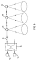
- an optical communication system which comprises a source 10 of light, light being passed by the source into an optical fibre 11.
- the source 10 can be a generally conventional source of optical light (usually of infra-red wavelength) which carries signal information and the optical fibre 11 may be of generally conventional construction and includes one or more discrete amplifiers 12 or an amplifier which is distributed along the fibre itself.
- the optical fibre includes antenna means 13 at spaced intervals along its length.
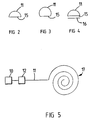
- the antenna means 13 comprises an extensive length of the optical fibre 11 which may be arranged so that light from within the fibre passes out of the fibre into free space. This may be done in a preferred arrangement by providing a length of the fibre formed as a "D-fibre" (the cross-section of which is shown in Figure 2), that is, the cross section of the fibre is reduced from its normally circular cross section to a semi circular cross section by a transverse bisecting flat or planar surface 15.
- D-fibre the cross-section of which is shown in Figure 2
- Such a construction is well known as a technique for removing light from the fibre and passing it to, for example, another fibre in contact therewith.
- the antenna means 13 may be in the form of optical fibre of between 1 and 100 metre length, and the amount of light transmitted may be between 10mW and 1W.
- the source 10 may be in the form of a laser which may provide 10mW, or 40mW power.
- the transmit means 13 comprises a 1 metre length of fibre, and it is desired to transmit 10mW of power, then if the laser has a power output of 40mW then the coupling between the core of the fibre and free space must be arranged so as to transmit a quarter of the power of the laser from the fibre evenly along that length of fibre.
- the so called "D"-fibre comprises a circular central core which is typically between 8 ⁇ m and 10 ⁇ m in diameter, of a glass of refractive index of the order of 1.454, surrounded by the D cross section cladding of glass of refractive index of 1.444 and of a diameter of about 125 ⁇ m.
- This glass cladding is surrounded by a coating of plastic (polymer) of a refractive index so as to allow light from within the cladding to spill into the coating, and the coating can have a typical diameter of between 250 and 400 ⁇ m, typically 350 ⁇ m.
- the d-value (the distance in ⁇ m from the periphery of the fibre core to the flat face) and/or the refractive index of the coating can be chosen to vary the power to be radiated from the fibre, and might be for example between about 1 and 25 ⁇ m.
- d-values For D-fibre matching standard system fibre and a coating index of 1.584 (at 589nm), d-values have been calculated which would provide fibre light losses of 0.05dB/m, 0.5dB/m and 10dB/m for use in various regimes.
- the light loss required would be of the order of 0.05dB/m and this requires a d-value of about 22 ⁇ m.
- D-fibre type can be chosen to suit run-lengths of a few metres for point source applications, tens of metres for office environments and hundreds of metres for airport lounges or railway termini. (The light is required to leak out slowly, for long fibre runs, to maintain sufficient power along the length, whereas in the office environment the power can be released over a shorter distance.) D-fibre can be made using any of these values with no additional complexity in the manufacturing technique.
- the starting point will be the relevant safety standard and this, when transmitted into the distance between a person and the transmit means, and the length of the transmit means, will indicate laser power required, and the efficiency of coupling between the fibre core and free space which is required in a particular circumstance.
- the cross section may be greater than semi circular as shown in Figure 3, ie, the transverse surface 15 may be spaced from the longitudinal axis of the fibre 1 so that less material is removed from the fibre.
- diffuser means 16 which provides a predetermined diffuse pattern of radiated light
- this diffuser means 16 may be in the form of scattering lenses (which may be formed, for example, of moulded plastic or may be formed by spraying transparent material onto the transverse flat surface 15, allowing the individual droplets to set and form lenticular elements which may be of random different focal lengths), a diffuse screen (which may be formed separately or may comprise a suitably roughened transverse flat surface 15), refractive lenses, or one or more holographic elements. Details of a holographic element suitable to the purpose is described in our copending EP 580 905A.
- the transmit means 13 may comprise scattering centres on a round fibre, or coatings on a D-fibre with scattering centres as will be described later.
- the effect is to create a diffuse distribution pattern of radiated light in free space which cannot be focused on to the retina or skin of a person with a lens in a manner such that the retina or skin can be damaged.
- the transmit means 13 can be arranged to radiate light into free space in a diffuse manner but in a predetermined pattern as is indicated at 14.
- the patterns may overlap or be separated as is desired.
- the optical fibre 11 may be arranged to traverse the ceiling of a room and patterns 14 covering the room may be provided.
- the power level in the fibre 11 will generally drop exponentially along the length of the feeder run. This can be compensated by adjusting the dynamic range of the optical receivers associated with the respective transmitters 13, or by saturating the feeder 11 with optical power from the source 10 and amplifier 12. Another possibility would be to use binary related transmit means along the fibre 11 such that the amount of power that can be leaked at each transmit means 13 is progressively increased by a factor of 2. To avoid having a very high power source at one end of the feeder, it would also be possible to have a half power source at each end.
- the feeder run 11 consists of an optical fibre doped with erbium ions, or with any dopant that produces optical amplification. It is then possible to pump the fibre at a shorter wavelength than the signal wavelength to excite the ions and thereby amplify the signal as it travels along the fibre.
- a fibre doped with erbium ions and carrying a signal at 1500nm could be pumped at a wavelength of 890nm. The 1500nm signal is then coupled from the fibre at each tapping 13 while the pump power at 980nm is retained by the fibre for optical amplification. In this way, the signal strength can be maintained over an indefinite length.
- the signals from the pump source 14 and the signal source 10 are coupled to the fibre 11 through a wavelength division multiplexer 15.
- a wavelength division multiplexer 15 By suitable choice of pump powers, doping densities, and rates at which the signal power is coupled out of the feeder, the distribution of coupled power along the feeder can be made essentially uniform.
- Figure 6 shows a transverse section of a fourth embodiment of fibre for use with the invention.
- Optical fibres are prone to breakage if put under tension, and it has become a well known technique to install optical fibres in a system by initially installing a conduit for the fibre which may be in the form of a tube.
- the conduit is of material which is not damaged by the inevitable bending and pulling which accompanies installation.
- the optical fibre is fed along the conduit by means of a flow of air.
- Such a method is described in EP0108590B.
- ballotini tiny glass beads
- ballotini of diameter between 3 and 18 ⁇ m
- coating material having the same refractive index as the UV coating and are used to thinly coat a D-fibre (typically 82nm D-fibre) substrate.
- Figure 7 shows a cross section of the optical fibre thereby coated.
- a desired arrangement of transparent conduits is mounted across the ceiling of the room into which the light is to be transmitted.
- the D-fibre is then blown into the conduit across the ceiling as described.
- the D-fibre orientation varies randomly along the transparent conduit and up to 50% of the available light is directed away from the useful direction for example towards the ceiling. Much of this wasted power can be regained by using a reflector behind the conduit.
- the arrangement provides illumination with a 3dB dynamic range at a desk height in an area 5m wide.
- the leakage rate is completely uniform along the fibre run direction.
- the d-value (the distance in ⁇ m from the periphery of the fibre core to the flat face) and/or the refractive index of the primary coating, can be altered to vary the power to be radiated from the fibre.
- d-values For D-fibre matching standard system fibre and a primary coating index of 1.584 (at 589nm), d-values have been calculated which can provide fibre light losses of 0.05dB/m, 0.5dB/m and 10dB/m for use in various situations. These calculations have shown that the D-fibre type can be chosen to suit cable run-lengths of a few metres for point source application, tens of metres for office environments and hundreds of metres for airport lounges or railway termini.
- the ballotini are scattered throughout the fibre coating as well as towards the outside edge. This provides scattering from within the coating.
- a special fibre which has a much higher Rayleigh scattering coefficient than normal.
- the scattering properties of the fibre are enhanced by growing small crystals in the fibre core or by forming the fibre itself from a highly and multiply doped silica glass.
- a fibre (which need not be a D-fibre) may be used to provide a leaky feed over 500 metres which scatters light out of the fibre at a rate of 40dB/km.
- the small crystals in the fibre core may be produced by controlled reheating of an optical fibre (or by slowing cooling the optical fibre after manufacture) through a temperature band between the glass transition temperature T G and the crystallisation temperature T X of the glass in question.
- a typical temperature band would be of the order of 500 to 1000°C and, depending upon the glass, the glass should be maintained in the desired temperature band for a period of time between less than one minute and one hour, typically one to two minutes.
- a length of D-fibre was fusion-spliced to the tail of a semiconductor communication laser of wavelength 1500nm.
- a silicon microlens array measuring 1cm 2 and containing 6400 lenses on a 250 ⁇ m grid was placed, in optical contact, on to part of the D-fibre flat.
- the light emitted by the panel of microlenses is symmetrically distributed normal to the panel and spatially incoherent. The power thus distributed can therefore be higher, before safety considerations impose a limit, than is the case for direct laser or LED distribution.
- the power emission lobe has a 38°, 3 dB half angle. In fact, 80% of the input power from the laser diode was detected in the output lobe. It is calculated that this would transmit signals over a 4m width at desk level, from a ceiling height of 2.5m.
- Quasi-continuous illumination could therefore be obtained by placing a microlens array every 4m along a cable run, spliced or connected into the transmission path. It is easy to imagine continuous distribution from suitably coated fibre, installed as a continuous length into a transparent conduit. This installation might be conveniently effected by the blown fibre technique for installing a fibre into a preinstalled conduit.
- the proportion of the light passing out of the fibre within a 5cm aperture will be 5/200 of the total light, although it is understood that there would be a greater amount of light transmitted from the fibre at the source end rather than the end remote from the source. This makes for inherent safety.
- the arrangement of this invention has a multiplicity of uses.
- the light transmitter may be provided in the form of the fibre 11 extending across the ceiling of a room, and a signal from the fibre 11 carrying broadcast information may be transmitted into the room from where it may be picked up by, for example, suitable receivers (such as light sensitive semiconductor elements) forming part of computers (such as portable computers) or televisions.
- suitable receivers such as light sensitive semiconductor elements
- computers such as portable computers
- the apparatus of the invention is particularly useful in circumstances where, for example, the information is either broadcast as above described or where there is considerably more information to be broadcast to the terminal than from the terminal.
- the information is either broadcast as above described or where there is considerably more information to be broadcast to the terminal than from the terminal.
- a very simple solid or radio link can be provided between the terminal and the database which can pass the necessary interrogation information at a relatively slow rate, but the data which the terminal requires to answer the particular question can be considerable and this can be transported by a system of the invention at a very high data rate.
- an optical communication system in accordance with the invention may be provided remotely from houses or buildings and broadcast information, for example, television signals, may be broadcast to the houses or buildings from a remote location to be received by receivers.
- broadcast information for example, television signals
- the arrangement of the invention may be used in the common situation inside a theatre where an audio signal is impressed upon the light within the fibre and may be transmitted to a suitable headset.
Landscapes
- Engineering & Computer Science (AREA)
- Computing Systems (AREA)
- Physics & Mathematics (AREA)
- Electromagnetism (AREA)
- Computer Networks & Wireless Communication (AREA)
- Signal Processing (AREA)
- Optical Couplings Of Light Guides (AREA)
- Light Guides In General And Applications Therefor (AREA)
Claims (26)
- Optisches Kommunikationssystem für die Kommunikation im freien Raum mit einer optischen Quelle (10), die eine Einrichtung zum Modulieren der optischen Ausgabe aufweist, um ein optisches Signal zu liefern, wobei die optische Quelle (10) mit einer optischen Faser (11) verbunden ist, um durch sie das Signal zu leiten, wobei die optische Faser (11) eine Antenneneinrichtung (13) mit einem Übertragungsbereich der optischer Faser aufweist, der einen Kern sowie eine Umhüllung hat, dadurch gekennzeichnet, daßdie Umhüllung des Übertragungsbereichs der optischen Faser eine im wesentlichen flache Oberfläche (15) aufweist, die sich längs ihrer Länge erstreckt, sowie eine Einrichtung, mit der durch die im wesentlichen flache Oberfläche Licht aus der optischen Faser (11) ausgekoppelt werden kann, sowie eine Streueinrichtung (16) zum inkohärenten Streuen des so aus der Faser ausgekoppelten Lichts in den freien Raum;und daß mehrere Antenneneinrichtungen (13) längs der optischen Faser (11) beabstandet zueinander vorgesehen sind.
- Optisches Kommunikationssystem nach Anspruch 1, dadurch gekennzeichnet, daß
jeder Übertragungsbereich einer optischen Faser eine Ummantelung aufweist, die die Umhüllung umgibt. - Optisches Kommunikationssystem nach Anspruch 2, dadurch gekennzeichnet, daß
der Abstand zwischen dem Kern und der flachen Oberfläche (15) und die relativen Brechungsindices der Umhüllung und der Ummantelung so sind, daß das optische Signal von jedem Übertragungsbereich der optischen Faser in den freien Raum gestreut wird, um außerhalb der Faser (11) inkohärent gestreutes Licht zu erzeugen. - Optisches Kommunikationssystem nach einem der Ansprüche 1 bis 3,
dadurch gekennzeichnet, daß
sie bei jeder Antenneneinrichtung (13) das Licht von innerhalb der optischen Faser (11) um einen Winkel von größer als 90° bezüglich der Richtung, in die das Licht längs der Faser läuft, gestreut wird. - Optisches Kommunikationssystem nach einem der Ansprüche 1 bis 4,
dadurch gekennzeichnet, daß
jede Antenneneinrichtung (13) eine Einrichtung zum weiteren inkohärenten Streuen des Lichts in den freien Raum aufweist. - Optisches Kommunikationssystem nach Anspruch 5,
dadurch gekennzeichnet, daß
jede weitere Streueinrichtung einen Diffusor (16) in Form eines diffusen Schirms oder eines Streulinsenelements aufweist. - Optisches Kommunikationssystem nach Anspruch 6,
dadurch gekennzeichnet, daß
die Streulinsenelemente linsenartige Elemente (29) sind, die gebildet werden, indem transparentes Material auf zumindest eine der zumindest einen flachen Oberfläche gesprüht wird, wobei Tröpfchenbildung erlaubt wird. - Optisches Kommunikationssystem nach Anspruch 5,
dadurch gekennzeichnet, daß
jede weitere Streueinrichtung Glasperlen aufweist. - Optisches Kommunikationssystem nach Anspruch 8,
dadurch gekennzeichnet, daß
die Glasperlen Durchmesser im Bereich zwischen 3 und 18 µm haben. - Optisches Kommunikationssystem nach Anspruch 8 oder 9, soweit sie sich auf Anspruch 2 zurückbeziehen,
dadurch gekennzeichnet, daß
die Ummantelung für Licht transparent ist und die Glasperlen innerhalb der Ummantelung oder an der äußeren Oberfläche der Ummantelung oder an beiden Stellen vorgesehen sind. - Optisches Kommunikationssystem nach Anspruch 5,
dadurch gekennzeichnet, daß
jede weitere Streueinrichtung im Faserkern Unregelmäßigkeiten (30) aufweist. - Optisches Kommunikationssystem nach Anspruch 11,
dadurch gekennzeichnet, daß
die Unregelmäßigkeiten innerhalb des Faserkerns Kristalle aufweisen, die zu Rayleigh-Streuung führen. - Optisches Kommunikationssystem nach Anspruch 5,
dadurch gekennzeichnet, daß
jedes weitere Streuelement ein holographisches Element aufweist. - Optisches Kommunikationssystem nach Anspruch 13,
dadurch gekennzeichnet, daß
das holographische Element auf zumindest einer der im wesentlichen flachen Oberflächen (15) der Faser ausgebildet ist. - Optisches Kommunikationssystem nach einem der Ansprüche 1 bis 14,
dadurch gekennzeichnet, daß
aufeinanderfolgend oder beabstandet Übertragungsbereiche der optischen Faser derart angeordnet sind, daß ein zunehmender Anteil des verfügbaren Lichts in der Faser (11) übertragen wird, wodurch die von jedem Bereich übertragene Lichtmenge im wesentlichen gleich ist. - Optisches Kommunikationssystem nach einem der Ansprüche 1 bis 15,
dadurch gekennzeichnet, daß
jeder Übertragungsbereich der optischen Faser zwischen 1 und 100 m lang ist. - Optisches Kommunikationssystem nach einem der Ansprüche 1 bis 15,
dadurch gekennzeichnet, daß
jeder Übertragungsbereich der optischen Faser zwischen 1 und 10 m lang ist. - Optisches Kommunikationssystem nach Anspruch 16 oder 17,
dadurch gekennzeichnet, daß
die optische Quelle (10) dazu ausgelegt ist, ein optisches Signal zwischen 10 mW und 1 W längs der optischen Faser (11) zu übertragen. - Optisches Kommunikationssystem nach einem der Ansprüche 1 bis 18,
dadurch gekennzeichnet, daß
die optische Faser (11) einen Dotierungsstoff enthält, der dazu in der Lage ist, dann, wenn er stimuliert wird, das Signal aus der Quelle (10) dann, wenn es längs der Faser läuft, zu verstärken. - Optisches Kommunikationssystem nach Anspruch 19,
dadurch gekennzeichnet, daß
die optische Quelle (10) und eine Pumpquelle (14) mit der Faser (11) über einen Wellenlängenmultiplexer (15) verbunden sind, wobei die Pumpquelle (14) ein Signal bei einer kürzeren Wellenlänge als das Signal von der optischen Quelle (10) zur Stimulierung des Dotierungsstoffs in der Faser liefert. - Optisches Kommunikationssystem nach einem der Ansprüche 1 bis 20,
dadurch gekennzeichnet, daß
der Abstand (d) zwischen dem Rand des Kerns und der im wesentlichen flachen Oberfläche (15) der Umhüllung zwischen 1 und 10 µm liegt. - Optisches Kommunikationssystem nach Anspruch 21,
dadurch gekennzeichnet, daß
der Abstand (d) zwischen dem Rand des Kerns und der im wesentlichen flachen Oberfläche (15) der Umhüllung etwa 5 µm ist. - Optisches Kommunikationssystem nach einem der Ansprüche 3 bis 22, soweit sie sich auf Anspruch 2 zurückbeziehen,
dadurch gekennzeichnet, daß
die Umhüllung einen Durchmesser im Bereich von 250 bis 400 µm hat. - Optisches Kommunikationssystem nach Anspruch 23,
dadurch gekennzeichnet, daß
die Umhüllung durch eine Ummantelung umgeben ist, deren Durchmesser im Bereich von etwa 350 µm liegt. - Optisches Kommunikationssystem für die Kommunikation im freien Raum, mit einer optischen Quelle (10), die eine Einrichtung zum Modulieren der optischen Ausgabe aufweist, um ein optisches Signal zu liefern, wobei die optische Quelle (10) mit einer optischen Faser (11) verbunden ist, um durch sie das Signal zu leiten, wobei die optische Faser (11) eine Signalweiterleitungseinrichtung mit einem Weiterleitungsbereich der optischen Faser aufweist, der einen Kern sowie eine Umhüllung hat,
dadurch gekennzeichnet, daßder Kern optisch wirksame Unregelmäßigkeiten (13) aufweist, wodurch ein Teil des optischen Signals vom Übertragungsbereich der optischen Faser durch die Umhüllung gestreut wird, um inkohärente Streuung in den freien Raum außerhalb der Faser zu erzeugen;und daß mehrere optisch wirksame Unregelmäßigkeiten längs der optischen Faser (11) beabstandet voneinander vorgesehen sind. - Optisches Kommunikationssystem nach Anspruch 25,
dadurch gekennzeichnet, daß
die Unregelmäßigkeiten kleine Kristalle innerhalb des Faserkerns aufweisen, die Rayleigh-Streuung erzeugen.
Priority Applications (1)
| Application Number | Priority Date | Filing Date | Title |
|---|---|---|---|
| EP93917930A EP0653129B1 (de) | 1992-07-28 | 1993-07-28 | Einrichtung zur leitungsungebundenen signalübertragung mittels licht |
Applications Claiming Priority (4)
| Application Number | Priority Date | Filing Date | Title |
|---|---|---|---|
| EP92306885 | 1992-07-28 | ||
| EP92306885 | 1992-07-28 | ||
| EP93917930A EP0653129B1 (de) | 1992-07-28 | 1993-07-28 | Einrichtung zur leitungsungebundenen signalübertragung mittels licht |
| PCT/GB1993/001590 WO1994002997A1 (en) | 1992-07-28 | 1993-07-28 | Free space optical communication system |
Publications (2)
| Publication Number | Publication Date |
|---|---|
| EP0653129A1 EP0653129A1 (de) | 1995-05-17 |
| EP0653129B1 true EP0653129B1 (de) | 1997-06-04 |
Family
ID=8211450
Family Applications (1)
| Application Number | Title | Priority Date | Filing Date |
|---|---|---|---|
| EP93917930A Expired - Lifetime EP0653129B1 (de) | 1992-07-28 | 1993-07-28 | Einrichtung zur leitungsungebundenen signalübertragung mittels licht |
Country Status (6)
| Country | Link |
|---|---|
| US (1) | US5748813A (de) |
| EP (1) | EP0653129B1 (de) |
| AU (1) | AU4717393A (de) |
| DE (1) | DE69311345T2 (de) |
| ES (1) | ES2103484T3 (de) |
| WO (1) | WO1994002997A1 (de) |
Families Citing this family (22)
| Publication number | Priority date | Publication date | Assignee | Title |
|---|---|---|---|---|
| JP3461653B2 (ja) * | 1995-10-19 | 2003-10-27 | 富士ゼロックス株式会社 | 光ファイバ伝送と自由空間伝送に共用可能な光送受信器および光通信ネットワーク |
| US6931183B2 (en) | 1996-03-29 | 2005-08-16 | Dominion Lasercom, Inc. | Hybrid electro-optic cable for free space laser antennas |
| US6348986B1 (en) * | 1996-03-29 | 2002-02-19 | Dominion Lasercom. Inc. | Wireless fiber-coupled telecommunication systems based on atmospheric transmission of laser signals |
| US6239888B1 (en) | 1998-04-24 | 2001-05-29 | Lightpointe Communications, Inc. | Terrestrial optical communication network of integrated fiber and free-space links which requires no electro-optical conversion between links |
| US6868237B2 (en) | 1998-04-24 | 2005-03-15 | Lightpointe Communications, Inc. | Terrestrial optical communication network of integrated fiber and free-space links which requires no electro-optical conversion between links |
| JP2002521856A (ja) * | 1998-07-16 | 2002-07-16 | テラビーム・コーポレーション | 自由空間を通じてデータを送受信する光通信システム |
| US6763195B1 (en) * | 2000-01-13 | 2004-07-13 | Lightpointe Communications, Inc. | Hybrid wireless optical and radio frequency communication link |
| WO2002073845A2 (en) * | 2001-03-09 | 2002-09-19 | Lightpointe Communications, Inc. | Free space optical communication network |
| US6889009B2 (en) * | 2001-04-16 | 2005-05-03 | Lightpointe Communications, Inc. | Integrated environmental control and management system for free-space optical communication systems |
| US20020171896A1 (en) * | 2001-05-21 | 2002-11-21 | Lightpointe Communications, Inc. | Free-space optical communication system employing wavelength conversion |
| EP1335508B1 (de) * | 2002-02-11 | 2007-03-07 | Alcatel | Schutzverfahren und Schnittstelle für fiberoptische Systeme |
| US7583642B2 (en) * | 2002-09-10 | 2009-09-01 | Harris Corporation | Communication system providing hybrid optical/wireless communications and related methods |
| DE60316178T2 (de) * | 2002-10-24 | 2008-06-05 | Nakagawa Laboratories, Inc. | Kommunikationsvorrichtung mit beleuchtungslicht |
| US20040120717A1 (en) * | 2002-12-18 | 2004-06-24 | Lightpointe Communications, Inc. | Extended source free-space optical communication system |
| JP2005284250A (ja) * | 2004-03-04 | 2005-10-13 | Nakagawa Kenkyusho:Kk | 通信システム及び漏洩光ファイバ |
| WO2008018281A1 (en) * | 2006-08-07 | 2008-02-14 | Hamamatsu Photonics K.K. | Mobile optical communication system and mobile optical communication method |
| US9590733B2 (en) * | 2009-07-24 | 2017-03-07 | Corning Optical Communications LLC | Location tracking using fiber optic array cables and related systems and methods |
| GB0915163D0 (en) | 2009-09-01 | 2009-10-07 | Board | A communication system |
| WO2018102922A1 (en) | 2016-12-06 | 2018-06-14 | Lensvector Inc. | Liquid crystal beam control |
| GB201706127D0 (en) * | 2017-04-18 | 2017-05-31 | Purelifi Ltd | Luminaire system for optical wireless communication |
| US10277316B1 (en) | 2017-05-01 | 2019-04-30 | The United States Of America As Represented By The Secretary Of The Air Force | Free space optical headset |
| US11234078B1 (en) * | 2019-06-27 | 2022-01-25 | Apple Inc. | Optical audio transmission from source device to wireless earphones |
Family Cites Families (7)
| Publication number | Priority date | Publication date | Assignee | Title |
|---|---|---|---|---|
| JPS5495104A (en) * | 1978-01-12 | 1979-07-27 | Mitsubishi Electric Corp | Optical fiber leakage communication unit |
| JPS5599855A (en) * | 1979-01-25 | 1980-07-30 | Japanese National Railways<Jnr> | Mobile body communication system |
| JPS572005A (en) * | 1980-06-05 | 1982-01-07 | Hitachi Cable Ltd | Leakage optical fiber |
| GB2169464B (en) * | 1985-01-09 | 1988-09-21 | Stc Plc | Optical fibre transmission systems |
| JP2629769B2 (ja) * | 1988-02-02 | 1997-07-16 | 旭硝子株式会社 | 面状照明装置とその用途 |
| US4929050A (en) * | 1988-10-31 | 1990-05-29 | Unisys Corporation | Traveling wave fiber optic interferometric sensor and method of polarization poling fiber optic |
| DE3915977A1 (de) * | 1989-05-17 | 1990-11-29 | Standard Elektrik Lorenz Ag | Vorrichtung zur uebertragung eines optischen signales |
-
1993
- 1993-07-28 US US08/379,449 patent/US5748813A/en not_active Expired - Lifetime
- 1993-07-28 AU AU47173/93A patent/AU4717393A/en not_active Abandoned
- 1993-07-28 DE DE69311345T patent/DE69311345T2/de not_active Expired - Fee Related
- 1993-07-28 WO PCT/GB1993/001590 patent/WO1994002997A1/en not_active Ceased
- 1993-07-28 ES ES93917930T patent/ES2103484T3/es not_active Expired - Lifetime
- 1993-07-28 EP EP93917930A patent/EP0653129B1/de not_active Expired - Lifetime
Also Published As
| Publication number | Publication date |
|---|---|
| DE69311345T2 (de) | 1997-11-06 |
| AU4717393A (en) | 1994-02-14 |
| EP0653129A1 (de) | 1995-05-17 |
| US5748813A (en) | 1998-05-05 |
| ES2103484T3 (es) | 1997-09-16 |
| DE69311345D1 (de) | 1997-07-10 |
| WO1994002997A1 (en) | 1994-02-03 |
Similar Documents
| Publication | Publication Date | Title |
|---|---|---|
| US5748813A (en) | Free space optical communication system | |
| Kihara et al. | Characteristics of thermally expanded core fiber | |
| US4173390A (en) | Fiber optic T-coupler | |
| US20110135261A1 (en) | Optical waveguide, optical waveguide module and method for forming optical waveguide | |
| US6424765B1 (en) | Optical device and method of making the same | |
| US20040120717A1 (en) | Extended source free-space optical communication system | |
| JPH02150806A (ja) | 高光度電磁線送信用光ファイバー束 | |
| CA2772467C (en) | Communication system | |
| US20040264972A1 (en) | Open-Path/Free-Space Optical Communication System and Method Using Reflected or Backscattered Light | |
| CA2013246C (en) | Atmospheric optical communication link | |
| US6965713B2 (en) | Optical beam generating and shaping device | |
| CA2352950A1 (en) | Article comprising a multimode optical fiber coupler | |
| CA2166256C (en) | Optical signal transceiver for use with diffusely transmitted optical radiation | |
| RU2174741C1 (ru) | Устройство для атмосферной оптической связи | |
| Smyth et al. | Optical wireless: New enabling transmitter technologies | |
| US20020141021A1 (en) | Optical communications system and method of protecting an optical route | |
| RU2002118233A (ru) | Оптическое волокно и система передачи оптических сигналов, использующая указанное оптическое волокно | |
| FR2790108B1 (fr) | Fibre optique a grande surface effective et a forte dispersion chromatique | |
| US20020071647A1 (en) | Multi-clad optical fiber and amplifier | |
| JP2002084232A (ja) | 空中光通信のための方法および送受信機 | |
| US20040146308A1 (en) | Receiver for optical transmission systems in air with increased receiving area and method for increasing the receiving area of such a receiver | |
| US6412989B1 (en) | Directable laser transmission module | |
| RU22279U1 (ru) | Система оптической связи | |
| US20040096174A1 (en) | Optical fiber having an expanded mode field diameter and methods of providing such a fiber | |
| EP1146669B1 (de) | Optisches Übertragungssystem und Verfahren zum Schützen einer optischen Strecke |
Legal Events
| Date | Code | Title | Description |
|---|---|---|---|
| PUAI | Public reference made under article 153(3) epc to a published international application that has entered the european phase |
Free format text: ORIGINAL CODE: 0009012 |
|
| 17P | Request for examination filed |
Effective date: 19950214 |
|
| AK | Designated contracting states |
Kind code of ref document: A1 Designated state(s): DE ES FR GB IT NL SE |
|
| 17Q | First examination report despatched |
Effective date: 19960207 |
|
| GRAG | Despatch of communication of intention to grant |
Free format text: ORIGINAL CODE: EPIDOS AGRA |
|
| GRAH | Despatch of communication of intention to grant a patent |
Free format text: ORIGINAL CODE: EPIDOS IGRA |
|
| GRAH | Despatch of communication of intention to grant a patent |
Free format text: ORIGINAL CODE: EPIDOS IGRA |
|
| GRAA | (expected) grant |
Free format text: ORIGINAL CODE: 0009210 |
|
| AK | Designated contracting states |
Kind code of ref document: B1 Designated state(s): DE ES FR GB IT NL SE |
|
| ITF | It: translation for a ep patent filed | ||
| REF | Corresponds to: |
Ref document number: 69311345 Country of ref document: DE Date of ref document: 19970710 |
|
| PG25 | Lapsed in a contracting state [announced via postgrant information from national office to epo] |
Ref country code: SE Effective date: 19970904 |
|
| REG | Reference to a national code |
Ref country code: ES Ref legal event code: FG2A Ref document number: 2103484 Country of ref document: ES Kind code of ref document: T3 |
|
| ET | Fr: translation filed | ||
| PLBE | No opposition filed within time limit |
Free format text: ORIGINAL CODE: 0009261 |
|
| STAA | Information on the status of an ep patent application or granted ep patent |
Free format text: STATUS: NO OPPOSITION FILED WITHIN TIME LIMIT |
|
| 26N | No opposition filed | ||
| PGFP | Annual fee paid to national office [announced via postgrant information from national office to epo] |
Ref country code: NL Payment date: 19980629 Year of fee payment: 6 |
|
| PGFP | Annual fee paid to national office [announced via postgrant information from national office to epo] |
Ref country code: ES Payment date: 19980709 Year of fee payment: 6 |
|
| PG25 | Lapsed in a contracting state [announced via postgrant information from national office to epo] |
Ref country code: ES Free format text: LAPSE BECAUSE OF NON-PAYMENT OF DUE FEES Effective date: 19990729 |
|
| PG25 | Lapsed in a contracting state [announced via postgrant information from national office to epo] |
Ref country code: NL Free format text: LAPSE BECAUSE OF NON-PAYMENT OF DUE FEES Effective date: 20000201 |
|
| NLV4 | Nl: lapsed or anulled due to non-payment of the annual fee |
Effective date: 20000201 |
|
| REG | Reference to a national code |
Ref country code: GB Ref legal event code: 732E |
|
| REG | Reference to a national code |
Ref country code: GB Ref legal event code: IF02 |
|
| PGFP | Annual fee paid to national office [announced via postgrant information from national office to epo] |
Ref country code: FR Payment date: 20030609 Year of fee payment: 11 |
|
| PGFP | Annual fee paid to national office [announced via postgrant information from national office to epo] |
Ref country code: GB Payment date: 20030612 Year of fee payment: 11 |
|
| PGFP | Annual fee paid to national office [announced via postgrant information from national office to epo] |
Ref country code: DE Payment date: 20030625 Year of fee payment: 11 |
|
| REG | Reference to a national code |
Ref country code: ES Ref legal event code: FD2A Effective date: 20000810 |
|
| PG25 | Lapsed in a contracting state [announced via postgrant information from national office to epo] |
Ref country code: GB Free format text: LAPSE BECAUSE OF NON-PAYMENT OF DUE FEES Effective date: 20040728 |
|
| PG25 | Lapsed in a contracting state [announced via postgrant information from national office to epo] |
Ref country code: DE Free format text: LAPSE BECAUSE OF NON-PAYMENT OF DUE FEES Effective date: 20050201 |
|
| GBPC | Gb: european patent ceased through non-payment of renewal fee |
Effective date: 20040728 |
|
| PG25 | Lapsed in a contracting state [announced via postgrant information from national office to epo] |
Ref country code: FR Free format text: LAPSE BECAUSE OF NON-PAYMENT OF DUE FEES Effective date: 20050331 |
|
| REG | Reference to a national code |
Ref country code: FR Ref legal event code: ST |
|
| PG25 | Lapsed in a contracting state [announced via postgrant information from national office to epo] |
Ref country code: IT Free format text: LAPSE BECAUSE OF NON-PAYMENT OF DUE FEES Effective date: 20050728 |