EP0652401A2 - Outdoor luminaire with a device for securing it to a mast - Google Patents
Outdoor luminaire with a device for securing it to a mast Download PDFInfo
- Publication number
- EP0652401A2 EP0652401A2 EP94112387A EP94112387A EP0652401A2 EP 0652401 A2 EP0652401 A2 EP 0652401A2 EP 94112387 A EP94112387 A EP 94112387A EP 94112387 A EP94112387 A EP 94112387A EP 0652401 A2 EP0652401 A2 EP 0652401A2
- Authority
- EP
- European Patent Office
- Prior art keywords
- luminaire
- flange
- mast
- lamp
- connecting piece
- Prior art date
- Legal status (The legal status is an assumption and is not a legal conclusion. Google has not performed a legal analysis and makes no representation as to the accuracy of the status listed.)
- Granted
Links
Images

Classifications
-
- F—MECHANICAL ENGINEERING; LIGHTING; HEATING; WEAPONS; BLASTING
- F21—LIGHTING
- F21V—FUNCTIONAL FEATURES OR DETAILS OF LIGHTING DEVICES OR SYSTEMS THEREOF; STRUCTURAL COMBINATIONS OF LIGHTING DEVICES WITH OTHER ARTICLES, NOT OTHERWISE PROVIDED FOR
- F21V21/00—Supporting, suspending, or attaching arrangements for lighting devices; Hand grips
- F21V21/10—Pendants, arms, or standards; Fixing lighting devices to pendants, arms, or standards
- F21V21/116—Fixing lighting devices to arms or standards
-
- F—MECHANICAL ENGINEERING; LIGHTING; HEATING; WEAPONS; BLASTING
- F21—LIGHTING
- F21S—NON-PORTABLE LIGHTING DEVICES; SYSTEMS THEREOF; VEHICLE LIGHTING DEVICES SPECIALLY ADAPTED FOR VEHICLE EXTERIORS
- F21S8/00—Lighting devices intended for fixed installation
- F21S8/08—Lighting devices intended for fixed installation with a standard
-
- F—MECHANICAL ENGINEERING; LIGHTING; HEATING; WEAPONS; BLASTING
- F21—LIGHTING
- F21W—INDEXING SCHEME ASSOCIATED WITH SUBCLASSES F21K, F21L, F21S and F21V, RELATING TO USES OR APPLICATIONS OF LIGHTING DEVICES OR SYSTEMS
- F21W2131/00—Use or application of lighting devices or systems not provided for in codes F21W2102/00-F21W2121/00
- F21W2131/10—Outdoor lighting
- F21W2131/103—Outdoor lighting of streets or roads
Definitions
- the invention relates to an outdoor lamp according to the preamble of claim 1 and in particular a device for fastening it to a mast.
- a connecting piece between the lamp housing and the mast end in this known solution is an assembly member provided that has an angular cover piece, on the outside of which a sleeve is attached, with which the lamp can be placed on a mast end.
- the cover piece on the outside of the housing rests against both its lower wall and its rear wall and screwed on covering the two housing openings.
- the lower wall and the rear wall of the housing form an angle of 90 ° to 105 ° at the point at which the cover piece is arranged, and the mounting element is designed so that the figure axis of the external sleeve is almost vertical runs to one of these walls.
- the mounting member can be used both for post-top and post-top luminaires.
- the invention is therefore based on the object of specifying a further solution for an outdoor lamp with a device for mast mounting of the type mentioned, which can be used universally, allows simple mounting of the lamp even with different angles of inclination and thereby enables a reliable connection between lamp and mast end .
- the connecting piece can also be oriented by rotating the lamp housing by 180 ° in such a way that it is suitable for both types of fastening, in any case completely covering the lamp opening.
- this mast attachment is designed so that it can be adjusted in its angle of inclination with respect to the longitudinal axis of the lamp in an angular range that covers the angle of inclination of the lamp with respect to the road surface that occurs in practice.
- This solution according to the invention also allows a pre-assembly of the lamp, in which the connector on the lamp housing is already fixed so that the pre-assembled lamp, for example from a work platform, is only pushed onto the mast end after cable entry into the mast and there by tightening one Fixing screw must be set.
- this device can also be designed such that it centers itself on the lamp housing and is therefore particularly easy to install.
- an assembly aid can be provided for an exact adjustment of the inclination angle, so that a special adjustment process is unnecessary here. All of these configurations are such that the installation position once selected is reversible, ie the lamp can be installed in a different position at any time, for example when converting the lighting system, with the aid of the newly set connecting piece.
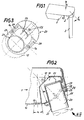
- a street lamp is shown schematically with a lamp body 1, which is placed on a fixture 2 for mast mounting on the end of a lamp mast 3 and firmly connected to this.
- a rounding of the mast-side wall of the lamp body 1 and a corresponding configuration of the contact surface of the device 2 for mast attachment to the lamp body 1 is shown schematically and highlighted by a double arrow labeled ⁇ that the lamp body 1 is to be arranged in relation to this device 2 for mast mounting by this same active ⁇ .
- FIG. 2 shows a cross section of a section from FIG. 1, which is intended to illustrate in particular the design of the device 2 for mast attachment.
- This cross-sectional illustration clearly shows that the housing 10 of the lamp body 1 is rounded in a circular arc on the wall part facing the lamp mast 3.
- a luminaire opening 11 is formed in the lower quadrant of this housing part by housing wall parts which recess inwards and which almost completely fills this quadrant.
- An inner wall of this lamp opening 11 has an opening 12 for the cable feed into the lamp.
- this lamp opening 11, as indicated in Figure 2 by an arrow labeled III, IV, is again shown in a schematic side view.
- This view in conjunction with FIG. 2 shows that the lamp housing 10, comprising the lamp opening 11 on all sides, here jumping back approximately by the thickness of the housing wall, is pulled inwards.
- a curved contact surface 13 is formed in the luminaire housing 10 in the region of the luminaire opening 11 and has a radius R in the plane perpendicular to the longitudinal plane of the luminaire.
- a connecting piece 20, as a further functionally essential part of the device 2 for mast attachment, has a central tube flange 21 which is covered on the light side by a perforated base plate 22 and is open at the outer end for receiving the mast end 31, indicated by dash-dotted lines in FIG. 2 .
- a curved collar Surrounding this pipe flange 21 on the outside, a curved collar is attached to it, which corresponds to the contact surface 13 of the lamp housing in the curvature and forms a fastening flange 23 of the connecting piece 20.
- FIG. 3 as indicated by the arrow III, IV in FIG. 2, a side view of this connecting piece 20 is shown in detail.
- This view illustrates that in the mounting flange 23 to, both sides of the pipe flange 21 slots 24 are provided. These take up fastening screws 14 which engage in threaded bores 15 in the contact surface 13 of the lamp housing 10.
- FIGS 2 and 3 also show that the mounting flange 23 is attached to the pipe flange 21 of the connector 20 via stiffening ribs 25, which include a mounting eye 26, stiffened.
- this fastening eye 26 there is a groove 27 running parallel to the outer wall of the pipe flange 21, into which a threaded nut 28, is rotatably fixed, inserted.
- the fastening eye 26 also has a through hole running perpendicular to the side wall of the tube flange 21. This through hole receives an Allen screw 29, which is screwed into the threaded nut 28 and thereby fixes the connecting piece 20 to the mast end 31 by tensioning the pipe flange 21 with respect to the mast end 31 used.
- FIG. 5 shows a detail of the connection of the fastening flange 23 to the lamp housing 10 in a section which is parallel to the sectional view in FIG. 2.
- This illustration shows that an outwardly projecting knob 17 is provided in the contact surface 13, in the area of the threaded bores 15 embedded in it.
- the outer contour of this knob 17 corresponds to a plurality of groove-shaped recesses 16 on the mounting flange 23.
- this embodiment serves to fix the connecting piece 20 on Luminaire housing 10 as an adjustment aid for determining the angle of inclination ⁇ when mounting the luminaire and as a safeguard against the connecting piece 20 slipping relative to the luminaire housing 10.
- the device for mast attachment described enables the light to be preassembled conveniently, because in every application it is determined for the assembly which mast shape is present and by what angle ⁇ the light should be positioned relative to the mast end.
- the connector 20 can be attached to the luminaire housing 10 in accordance with the respective application. From a work platform, the luminaire can then be plugged directly onto the mast end 31 via the pipe flange 21 of the connector 20 after the cable entry into the mast 3. To fix the lamp mechanically, only the Allen screw 29 is then tightened.
- the lamp opening 11 is always covered by the mounting flange 23 of the connector 20, regardless of the respective angular position ⁇ of the connector 20 with respect to the lamp housing. It is a design detail of the embodiment described here that the outside of the mounting flange 23 is flush with the outer contour of the lamp housing 10 because the contact surface 13 of the lamp housing 10 is drawn inwards. This design detail helps to align the connector 20 with the lamp body 1, but could also be solved differently.
- the connector 20 is rotated by 180 ° placed on the lamp housing 10.
- different angular positions ⁇ of the connecting piece 20 with respect to the luminaire housing 10 are possible, which can be seen immediately from the preceding description and is therefore no longer shown in further examples.
- the different positions of the connector 20 relative to the lamp housing 10 in the examples shown with reference to Figures 2, 6 and 7 also illustrate how the design of the cavity given by the lamp opening 11 takes into account the different positions of the tube flange 21 in the possible positions of the connector 20 and optimizes the utilization of this cavity with high rigidity of the luminaire mast.
- Different braid diameters at the mast ends 31 can then be taken into account by different diameters of the pipe flanges 21 in each case adapted to a specific braid diameter of connecting pieces 20.
Abstract
Description
Die Erfindung bezieht sich auf eine Außenleuchte gemäß dem Oberbegriff des Patentanspruches 1 sowie insbesondere eine Vorrichtung zu ihrer Befestigung an einem Mast.The invention relates to an outdoor lamp according to the preamble of
Fur Außenleuchten ist eine Vielzahl von Befestigungsmöglichkeiten bekannt, die nebeneinander je nach dem Anwendungsfall eingesetzt werden. Selbst wenn man sich, wie im vorliegenden Fall, auf die Anwendungsfälle beschränkt, bei denen die Außenleuchte an einem Mast befestigt wird, gibt es wegen der unterschiedlichen Mastformen, aber auch der Forderung, die Leuchte mit unterschiedlichen Neigungen gegenüber der von ihr beleuchteten Straßendecke anzuordnen, immer noch eine Vielzahl unterschiedlicher Befestigungsformen.A large number of fastening options are known for outdoor lights, which are used next to one another depending on the application. Even if, as in the present case, you restrict yourself to the applications in which the outdoor lamp is attached to a mast, there are, because of the different mast shapes, but also the requirement to arrange the lamp with different inclinations in relation to the street surface it illuminates, still a variety of different attachment types.
Undenkbar wäre es, für jede einzelne Befestigungsart eine individuelle Vorrichtung zum Befestigen der Leuchte an dem Mastende zu schaffen, weil ein derart umfangreiches Zubehörprogramm in der Herstellung aufwendig, in der Lagerhaltung zu teuer sowie bei der Montage mit Sicherheit immer wieder eine kostensteigernde Fehlerursache wäre. Es hat deshalb nicht an Versuchen gefehlt, die Verbindung zwischen der Leuchte und dem Mastende konstruktiv so auszugestalten, daß sie sowohl bei einer Mastansatz- als auch bei einer Mastaufsatzleuchte verwendbar ist. So ist beispielsweise aus der DE-C2-32 37 892 eine Mastleuchte bekannt, deren Gehäuse an der Unterwand und in der Rückwand je eine Öffnung für die Montage auf bzw. an einem Ende eines Lichtmastes aufweist. Als Verbindungsstück zwischen dem Leuchtengehäuse und dem Mastende ist bei dieser bekannten Lösung ein Montageorgan vorgesehen, das ein winkelförmiges Abdeckstück besitzt, an dem außen eine Muffe angebracht ist, mit der die Leuchte auf ein Mastende aufsetzbar ist. Im montierten Zustand der Mastleuchte ist das Abdeckstück an der Außenseite des Gehäuses sowohl an dessen Unterwand als auch dessen Rückwand anliegend und dabei die beiden Gehäuseöffnungen abdeckend angeschraubt.It would be inconceivable to create an individual device for attaching the luminaire to the mast end for each individual type of attachment, because such an extensive range of accessories is complex to manufacture, too expensive to keep in stock, and would always be a cost-increasing cause of error during assembly. There has therefore been no lack of attempts to constructively design the connection between the lamp and the mast end in such a way that it can be used both with a post-top and with a post-top lamp. For example, from DE-C2-32 37 892 a mast light is known, the housing of which has an opening on the lower wall and one in the rear wall for mounting on or at one end of a light pole. As a connecting piece between the lamp housing and the mast end in this known solution is an assembly member provided that has an angular cover piece, on the outside of which a sleeve is attached, with which the lamp can be placed on a mast end. In the assembled state of the mast light, the cover piece on the outside of the housing rests against both its lower wall and its rear wall and screwed on covering the two housing openings.
Bei einer der Ausführungsformen der bekannten Lösung bilden die Unterwand und die Rückwand des Gehäuses an der Stelle, an der das Abdeckstück angeordnet ist, einen Winkel von 90° bis 105° und das Montageorgan ist dazu so ausgebildet, daß die Figurenachse der außenstehenden Muffe nahezu senkrecht zu einer dieser Wände verläuft. Bei dieser Ausgestaltung ist das Montageorgan sowohl bei Mastansatz- als auch bei Mastaufsatzleuchten einsetzbar. Diese bekannte Lösung ist somit bei verschiedenen Mastformen ohne weiteres einsetzbar und dabei dennoch konstruktiv relativ einfach. Allerdings bietet sie keine Möglichkeit, einen vorgegebenen Neigungswinkel der Leuchte gegenüber der Horizontalen der Straßendecke einzustellen.In one embodiment of the known solution, the lower wall and the rear wall of the housing form an angle of 90 ° to 105 ° at the point at which the cover piece is arranged, and the mounting element is designed so that the figure axis of the external sleeve is almost vertical runs to one of these walls. In this embodiment, the mounting member can be used both for post-top and post-top luminaires. This known solution can therefore be used with various mast shapes without any problems and is nevertheless structurally relatively simple. However, it does not offer the possibility of setting a predetermined angle of inclination of the lamp with respect to the horizontal of the road surface.
Der Erfindung liegt daher die Aufgabe zugrunde, für eine Außenleuchte mit einer Vorrichtung zur Mastbefestigung der eingangs genannten Art eine weitere Lösung anzugeben, die universell einsetzbar ist, ein einfaches Montieren der Leuchte auch mit unterschiedlichen Neigungswinkeln gestattet und dabei eine betriebssichere Verbindung zwischen Leuchte und Mastende ermöglicht.The invention is therefore based on the object of specifying a further solution for an outdoor lamp with a device for mast mounting of the type mentioned, which can be used universally, allows simple mounting of the lamp even with different angles of inclination and thereby enables a reliable connection between lamp and mast end .
Bei einer Außenleuchte der eingangs genannten Art wird diese Aufgabe erfindungsgemäß durch die im Kennzeichen des Patentanspruches 1 beschriebenen Merkmale gelöst.In an outdoor lamp of the type mentioned, this object is achieved according to the invention by the features described in the characterizing part of
Für die Bauform der Leuchte, die nur eine einzige Öffnung für das Zuführen der Versorgungsleitungen besitzt, spielt es also keine Rolle, ob sie als Mastansatz- oder als Mastaufsatzleuchte benutzt wird, sie ist in jedem Fall universell einsetzbar. Wie bei der eingangs beschriebenen, bekannten Lösung kann auch hier das Verbindungsstück jeweils durch eine 180°-Drehung am Leuchtengehäuse so orientiert werden, daß es sich - in jedem Fall die Leuchtenöffnung vollständig abdeckend - für beide Befestigungsarten eignet. Darüber hinaus ist diese Mastbefestigung so ausgestaltet, daß sie in ihrem Neigungswinkel gegenüber der Leuchtenlängsachse in einem Winkelbereich einstellbar ist, der die in der Praxis vorkommenden Neigungswinkel der Leuchte gegenüber der Straßendecke überdeckt. Diese erfindungsgemäße Lösung erlaubt außerdem ein Vormontieren der Leuchte, bei der das Verbindungsstück am Leuchtengehäuse bereits so festgelegt wird, daß die so vormontierte Leuchte, beispielsweise von einer Arbeitsbühne aus, nach der Kabeleinführung in den Mast lediglich noch auf das Mastende aufgeschoben und dort durch Anziehen einer Befestigungsschraube festgelegt werden muß.For the design of the luminaire, which has only a single opening for the supply lines, it does not matter whether it is used as a post-top or post-top luminaire, it can be used universally in any case. As with the known solution described at the outset, the connecting piece can also be oriented by rotating the lamp housing by 180 ° in such a way that it is suitable for both types of fastening, in any case completely covering the lamp opening. In addition, this mast attachment is designed so that it can be adjusted in its angle of inclination with respect to the longitudinal axis of the lamp in an angular range that covers the angle of inclination of the lamp with respect to the road surface that occurs in practice. This solution according to the invention also allows a pre-assembly of the lamp, in which the connector on the lamp housing is already fixed so that the pre-assembled lamp, for example from a work platform, is only pushed onto the mast end after cable entry into the mast and there by tightening one Fixing screw must be set.
Gemäß vorteilhafter, in Unteransprüchen beschriebener Weiterbildungen der Erfindung kann diese Vorrichtung auch so ausgestaltet werden, daß sie sich am Leuchtengehäuse selbst zentriert und damit besonders montagefreundlich ist. Ebenso kann eine Montagehilfe für eine exakte Einstellung der Neigungswinkel vorgesehen sein, so daß sich hier ein besonderer Justiervorgang erübrigt. Dabei sind alle diese Ausgestaltungen so beschaffen, daß die einmal gewählte Einbaulage reversibel ist, d. h. die Leuchte jederzeit, beispielsweise bei einer Umrüstung der Beleuchtungsanlage, mit Hilfe des neu eingestellten Verbindungsstückes in einer anderen Position montierbar ist.According to advantageous developments of the invention described in the subclaims, this device can also be designed such that it centers itself on the lamp housing and is therefore particularly easy to install. Likewise, an assembly aid can be provided for an exact adjustment of the inclination angle, so that a special adjustment process is unnecessary here. All of these configurations are such that the installation position once selected is reversible, ie the lamp can be installed in a different position at any time, for example when converting the lighting system, with the aid of the newly set connecting piece.
Ausführungsbeispiele der Erfindung werden im folgenden anhand der Zeichnung näher erläutert, dabei zeigt
Figur 1 schematisch eine Mastaufsatzleuchte in erfindungsgemäßer Ausgestaltung, die eine um einen vorgegebenen Winkel α verstellbare Ausrichtung des Leuchtenkörpers gegenüber einer Mastbefestigungsvorrichtung ermöglicht, die auf das Mastende aufgesetzt ist und dieses mit dem Leuchtenkörper starr verbindet,- Figur 2 in einer Querschnittsdarstellung eine Detailansicht einer Ausführungsform dieser Mastbefestigung,
- Figur 3 eine Seitenansicht der Mastbefestigungsvorrichtung gemäß Figur 2,
- Figur 4 in einer der Ansicht von Figur 3 entsprechenden Sicht die Ausgestaltung eines leuchtenseitigen Flansches zum Anschluß an die Mastbefestigungsvorrichtung,
- Figur 5 in einem Ausschnitt eine Schraubverbindung zwischen der Mastbefestigungsvorrichtung und dem Flansch des Leuchtenkörpers und
- Figur 6 und 7 in der Figur 2 entsprechenden Querschnittsdarstellungen je ein weiteres Ausführungsbeispiel für eine Mastaufsatz- bzw. Mastansatzanordnung bei einer Straßenleuchte.
- 1 schematically shows a post-top luminaire in an embodiment according to the invention, which enables the luminaire body to be adjusted by a predetermined angle α relative to a mast fastening device which is placed on the mast end and rigidly connects it to the luminaire body,
- FIG. 2 shows a cross-sectional illustration of a detailed view of an embodiment of this mast attachment,
- FIG. 3 shows a side view of the mast fastening device according to FIG. 2,
- FIG. 4 in a view corresponding to the view in FIG. 3, the configuration of a lamp-side flange for connection to the mast fastening device,
- Figure 5 in a detail a screw connection between the mast mounting device and the flange of the lamp body and
- FIGS. 6 and 7 in cross-sectional representations corresponding to FIG. 2 each show a further exemplary embodiment of a mast-top or mast extension arrangement in a street lamp.
In Figur 1 ist schematisch eine Straßenleuchte mit einem Leuchtenkörper 1 dargestellt, der über eine Vorrichtung 2 zur Mastbefestigung auf das Ende eines Leuchtenmastes 3 aufgesetzt und mit diesem fest verbunden ist. Dabei ist durch eine Abrundung der mastseitigen Wand des Leuchtenkörpers 1 sowie eine entsprechende Ausgestaltung der Anlagefläche der Vorrichtung 2 zur Mastbefestigung an dem Leuchtenkörper 1 schematisch dargestellt und durch einen mit α bezeichneten Doppelpfeil hervorgehoben, daß der Leuchtenkörper 1 gegenüber dieser Vorrichtung 2 zur Mastbefestigung um eben diesen Wirkel α verschwenkbar anzuordnen ist. Damit werden unterschiedliche Anstellwinkel von Mastenden eines Leuchtenmastes 3 gegenüber der Vertikalen aufgefangen bzw. in einem gewissen Umfang bei Werten des Winkels α zwischen 0° und 15° je nach dem entsprechenden Anwendungsfall gewünschte Anstellwinkel der Leuchte ermöglicht.In Figure 1, a street lamp is shown schematically with a
In Figur 2 ist in einer Querschnittsdarstellung ein Ausschnitt aus Figur 1 gezeigt, der insbesondere die Ausgestaltung der Vorrichtung 2 zur Mastbefestigung illustrieren soll. In dieser Querschnittsdarstellung wird deutlicht, daß das Gehäuse 10 des Leuchtenkörpers 1 an dem dem Leuchtenmast 3 zugekehrten Wandteil kreisbogenförmig abgerundet ist. Ferner ist in dem unteren Quadranten dieses Gehäuseteiles durch nach innen rückspringende Gehäusewandteile eine Leuchtenöffnung 11 gebildet, die nahezu vollständig diesen Quadranten ausfüllt. Eine Innenwand dieser Leuchtenöffnung 11 weist einen Durchbruch 12 zur Kabelzuführung in die Leuchte auf.FIG. 2 shows a cross section of a section from FIG. 1, which is intended to illustrate in particular the design of the device 2 for mast attachment. This cross-sectional illustration clearly shows that the
In Figur 4 ist diese Leuchtenöffnung 11, wie in Figur 2 durch einen mit III, IV bezeichneten Pfeil angedeutet, nochmals in einer schematischen Seitenansicht dargestellt. Diese Ansicht zeigt in Verbindung mit Figur 2, daß das Leuchtengehäuse 10, die Leuchtenöffnung 11 allseitig umfassend, hier etwa um die Dicke der Gehäusewand zurückspringend, nach innen gezogen ist. Dadurch wird in dem Leuchtengehäuse 10 im Bereich der Leuchtenöffnung 11 eine gekrümmte Anlagefläche 13 gebildet, die in der zur Leuchtenlängsebene senkrecht stehenden Ebene einen Radius R aufweist.In Figure 4, this lamp opening 11, as indicated in Figure 2 by an arrow labeled III, IV, is again shown in a schematic side view. This view in conjunction with FIG. 2 shows that the lamp housing 10, comprising the lamp opening 11 on all sides, here jumping back approximately by the thickness of the housing wall, is pulled inwards. As a result, a
Ein Verbindungsstück 20, als weiteres funktional wesentliches Teil der Vorrichtung 2 zur Mastbefestigung, weist einen zentralen Rohrflansch 21 auf, der leuchtenseitig durch eine durchbrochene Grundplatte 22 abgedeckt und am äußeren Ende zur Aufnahme des Mastendes 31, in Figur 2 in strichpunktierten Linien angedeutet, offen ist. Diesen Rohrflansch 21 außen umfassend, ist daran ein gekrümmter Kragen angesetzt, der der Anlagefläche 13 des Leuchtengehäuses in der Krümmung entspricht und einen Befestigungsflansch 23 des Verbindungsstückes 20 bildet. Darauf hinzuweisen ist, daß die geometrische Zuordnung zwischen diesen beiden Flanschteilen des Verbindungsstückes 20 einerseits und der Lage der Anlagefläche 13 andererseits so gewählt ist, daß in beiden möglichen Orientierungslagen des Verbindungsstückes 20 bezüglich des Leuchtengehäuses 10 - bezogen auf eine horizontale Position der Leuchte 1 - der Rohrflansch 21 annähernd senkrecht bzw. parallel zur Leuchtenlängsachse steht, wie noch ausgeführt wird.A connecting
In Figur 3 ist, worauf der Pfeil III, IV in Figur 2 hinweist, als Detail eine Seitenansicht dieses Verbindungsstückes 20 gezeigt. Diese Ansicht verdeutlicht, daß in dem Befestigungsflansch 23 zu, beiden Seiten des Rohrflansches 21 Langlöcher 24 vorgesehen sind. Diese nehmen Befestigungsschrauben 14 auf, die in Gewindebohrungen 15 in der Anlagefläche 13 des Leuchtengehäuses 10 eingreifen.In FIG. 3, as indicated by the arrow III, IV in FIG. 2, a side view of this connecting
Figur 2 und 3 zeigen weiterhin, daß der Befestigungsflansch 23 am Rohrflansch 21 des Verbindungsstückes 20 über Versteifungsrippen 25, die ein Befestigungsauge 26 einschließen, konstruktiv versteift angesetzt ist. In diesem Befestigungsauge 26 ist eine parallel zur Außenwand des Rohrflansches 21 verlaufende Nut 27 vorgesehen, in die eine Gewindemutter 28, drehbeweglich fixiert, eingelegt ist. Das Befestigungsauge 26 weist außerdem eine senkrecht zur Seitenwand des Rohrflansches 21 verlaufende Durchgangsbohrung auf. Diese Durchgangsbohrung nimmt eine Inbusschraube 29 auf, die in die Gewindemutter 28 eingeschraubt ist und dabei durch Verspannen des Rohrflansches 21 gegenüber dem eingesetzten Mastende 31 das Verbindungsstück 20 kraftschlüssig am Mastende 31 festlegt.Figures 2 and 3 also show that the
In der Schnittdarstellung von Figur 2 ist unmittelbar gezeigt sowie in der Seitenansicht von Figur 3 ist mittels gestrichelter Linien angedeutet, daß die Längsausdehnung des Befestigungsflansches 23 des Verbindungsstückes 20 kürzer ist als die entsprechende Kreisbogenlänge der Anlagefläche 13 des Leuchtengehäuses 10. Somit ist das Verbindungsstück 20 in jeder Position innerhalb eines durch den Winkel α bezeichneten Schwenkbereiches am Leuchtengehäuse 10 zu fixieren. Konstruktiv ist die Größe dieses Winkels α, der üblichen Anforderungen bei Außenleuchten entsprechend etwa 15° beträgt, durch die Differenz der Kreisbogenlängen der Anlagefläche 13 des Leuchtengehäuses 10 sowie des Befestigungsflansches 23 des Verbindungsstückes 20 einerseits und die Länge der Langlöcher 24 andererseits festgelegt.In the sectional view of Figure 2 is shown directly and in the side view of Figure 3 is indicated by dashed lines that the longitudinal extent of the
In Figur 5 ist in einem Detailausschnitt die Verbindung des Befestigungsflansches 23 mit dem Leuchtengehäuse 10 in einem Schnitt gezeigt, der parallel zur Schnittdarstellung von Figur 2 geführt ist. Diese Darstellung verdeutlicht, daß in der Anlagefläche 13, im Bereich der in diese eingelassenen Gewindebohrungen 15, eine nach außen vorstehende Noppe 17 vorgesehen ist. Der Außenkontur dieser Noppe 17 entsprechen mehrere rillenförmige Ausnehmungen 16 auf dem Befestigungsflansch 23. Wie Figur 5 verdeutlicht, dient diese Ausgestaltung der Festlegung des Verbindungsstückes 20 am Leuchtengehäuse 10 als Einstellhilfe für die Festlegung des Neigungswinkels α bei der Leuchtenmontage sowie als Sicherung gegen ein mögliches Verrutschen des Verbindungsstückes 20 gegenüber dem Leuchtengehäuse 10.FIG. 5 shows a detail of the connection of the fastening
Die beschriebene Vorrichtung zur Mastbefestigung ermöglicht ein bequemes Vormontieren der Leuchte, weil in jedem Anwendungsfall für die Montage festliegt, welche Mastform vorliegt und um welchen Winkel α die Leuchte gegenüber dem Mastende angestellt sein soll. Somit kann das Verbindungsstück 20, dem jeweiligen Anwendungsfall entsprechend, an dem Leuchtengehäuse 10 befestigt werden, von einer Arbeitsbühne aus ist dann - nach der Kabeleinführung in den Mast 3 - die Leuchte über den Rohrflansch 21 des Verbindungsstückes 20 unmittelbar auf das Mastende 31 aufsteckbar. Zur mechanischen Festlegung der Leuchte ist dann lediglich die Inbusschraube 29 festzuziehen.The device for mast attachment described enables the light to be preassembled conveniently, because in every application it is determined for the assembly which mast shape is present and by what angle α the light should be positioned relative to the mast end. Thus, the
Bei der so montierten Leuchte ist die Leuchtenöffnung 11 unabhängig von der jeweiligen Winkelstellung α des Verbindungsstückes 20 gegenüber dem Leuchtengehäuse immer durch den Befestigungsflansch 23 des Verbindungsstückes 20 abgedeckt. Dabei ist es ein Gestaltungsdetail der hier beschriebenen Ausführungsform, daß die Außenseite des Befestigungsflansches 23 mit der Außenkontur des Leuchtengehäuses 10 fluchtend verläuft, weil die Anlagefläche 13 des Leuchtengehäuses 10 nach innen eingezogen ist. Dieses Gestaltungsdetail hilft, das Verbindungsstück 20 gegenüber dem Leuchtenkörper 1 auszurichten, könnte aber auch anders gelöst sein.In the lamp thus assembled, the
In Figur 6 und Figur 7 sind ergänzend zu Figur 2 zwei weitere Positionen für die Leuchtenbefestigung am Leuchtenmast 3 dargestellt. Während in Figur 2 eine obere Winkelstellung für die Neigung einer Mastaufsatzleuchte gezeigt ist, illustriert Figur 6 in der gleichen Querschnittsdarstellung die andere Extremposition des Verbindungsstückes 20 gegenüber dem Leuchtengehäuse 10, bei der dann die Leuchte bei vertikal stehendem Mast 3 horizontal ausgerichtet ist. Figur 7 zeigt dagegen ein Beispiel für die Verwendung derselben Leuchte als Mastansatzleuchte. Hier ist das Verbindungsstück 20 um 180° gedreht auf das Leuchtengehäuse 10 aufgesetzt. Auch bei Verwendungen als Mastansatzleuchte sind unterschiedliche Winkelstellungen α des Verbindungsstückes 20 gegenüber dem Leuchtengehäuse 10 möglich, was nach der vorausgehenden Beschreibung unmittelbar einzusehen ist und deshalb nicht mehr in weiteren Beispielen dargestellt ist.In FIG. 6 and FIG. 7, in addition to FIG. 2, two further positions for the lamp attachment to the lamp mast 3 are shown. While an upper angular position for the inclination of a post-top luminaire is shown in FIG. 2, illustrated Figure 6 in the same cross-sectional view, the other extreme position of the
Die unterschiedlichen Positionen des Verbindungsstückes 20 gegenüber dem Leuchtengehäuse 10 in den anhand von Figuren 2, 6 bzw. 7 gezeigten Beispielen verdeutlichen zudem, wie die Ausgestaltung des durch die Leuchtenöffnung 11 gegebenen Hohlraumes die unterschiedlichen Lagen des Rohrflansches 21 in den möglichen Positionen des Verbindungsstückes 20 berücksichtigt und bei hoher Festigkeit der Mastbefestigung der Leuchte die Ausnutzung dieses Hohlraumes optimiert.The different positions of the
Unterschiedliche Zopfdurchmesser an den Mastenden 31 können durch unterschiedliche Durchmesser der Rohrflansche 21 dann jeweils an einem bestimmten Zopfdurchmesser angepaßter Verbindungsstücke 20 berücksichtigt werden. Denkbar wäre es aber auch, den Unterschied zwischen dem auf einen großen Zopfdurchmesser bezogenen Innendurchmesser des Rohrflansches und einem kleineren Zopfdurchmesser jeweils mit Hilfe von einer über das Mastende 31 geschobenen Adaptermuffe auszugleichen.Different braid diameters at the mast ends 31 can then be taken into account by different diameters of the
Claims (9)
Applications Claiming Priority (2)
| Application Number | Priority Date | Filing Date | Title |
|---|---|---|---|
| DE4327964 | 1993-08-19 | ||
| DE4327964 | 1993-08-19 |
Publications (3)
| Publication Number | Publication Date |
|---|---|
| EP0652401A2 true EP0652401A2 (en) | 1995-05-10 |
| EP0652401A3 EP0652401A3 (en) | 1995-07-05 |
| EP0652401B1 EP0652401B1 (en) | 1998-07-01 |
Family
ID=6495590
Family Applications (1)
| Application Number | Title | Priority Date | Filing Date |
|---|---|---|---|
| EP94112387A Expired - Lifetime EP0652401B1 (en) | 1993-08-19 | 1994-08-08 | Outdoor luminaire with a device for securing it to a mast |
Country Status (3)
| Country | Link |
|---|---|
| EP (1) | EP0652401B1 (en) |
| AT (1) | ATE167927T1 (en) |
| DE (1) | DE59406365D1 (en) |
Cited By (9)
| Publication number | Priority date | Publication date | Assignee | Title |
|---|---|---|---|---|
| WO2004076918A2 (en) * | 2003-02-26 | 2004-09-10 | Leuci S.P.A. | Lighting apparatus with variable orientation in particular for street lighting |
| WO2007101471A1 (en) * | 2006-03-06 | 2007-09-13 | Fael S.P.A. | Monoblock lighting apparatus body preferably for outdoor environments with a variable angle supporting pole compartment |
| EP1852649A1 (en) * | 2006-04-21 | 2007-11-07 | Jürgen Müller | Solar powered mast luminaire |
| FR2937401A1 (en) * | 2008-10-17 | 2010-04-23 | Eclatec | Fixation knuckle for fixing lamp on post in e.g. road, has closing device to close opening of lamp, where device is efficient for rotational displacement of light, and angular tracking device to permit inclinational positioning of lamp |
| DE202010001578U1 (en) | 2010-01-29 | 2010-05-20 | Schefenacker Grah Sg Automotive D.O.O. | Pole attachment for attaching a luminaire to a luminaire pole |
| DE102010006330A1 (en) | 2010-01-29 | 2011-08-04 | GRAH Automotive d.o.o. | Pole attachment for attaching a luminaire body to a luminaire pole |
| WO2011120651A1 (en) | 2010-04-01 | 2011-10-06 | Siteco Beleuchtungstechnik Gmbh | Mast attachment means for street lights |
| EP2902700A1 (en) * | 2014-01-31 | 2015-08-05 | D W Windsor Limited | Mounting block |
| WO2019229045A1 (en) * | 2018-05-28 | 2019-12-05 | Schreder S.A. | Angle adjustment and rotation element |
Citations (1)
| Publication number | Priority date | Publication date | Assignee | Title |
|---|---|---|---|---|
| DE3237892C2 (en) | 1981-10-29 | 1987-09-17 | N.V. Philips' Gloeilampenfabrieken, Eindhoven, Nl |
Family Cites Families (3)
| Publication number | Priority date | Publication date | Assignee | Title |
|---|---|---|---|---|
| DE1120593B (en) * | 1959-02-04 | 1961-12-28 | Westinghouse Electric Corp | Light for fluorescent lamps |
| US3387866A (en) * | 1966-02-16 | 1968-06-11 | Gen Electric | Luminaire |
| DE9204644U1 (en) * | 1992-04-04 | 1992-10-08 | Zumtobel Licht Ges.M.B.H., Dornbirn, At |
-
1994
- 1994-08-08 EP EP94112387A patent/EP0652401B1/en not_active Expired - Lifetime
- 1994-08-08 DE DE59406365T patent/DE59406365D1/en not_active Expired - Lifetime
- 1994-08-08 AT AT94112387T patent/ATE167927T1/en not_active IP Right Cessation
Patent Citations (1)
| Publication number | Priority date | Publication date | Assignee | Title |
|---|---|---|---|---|
| DE3237892C2 (en) | 1981-10-29 | 1987-09-17 | N.V. Philips' Gloeilampenfabrieken, Eindhoven, Nl |
Cited By (15)
| Publication number | Priority date | Publication date | Assignee | Title |
|---|---|---|---|---|
| WO2004076918A2 (en) * | 2003-02-26 | 2004-09-10 | Leuci S.P.A. | Lighting apparatus with variable orientation in particular for street lighting |
| WO2004076918A3 (en) * | 2003-02-26 | 2004-12-23 | Leuci S P A | Lighting apparatus with variable orientation in particular for street lighting |
| WO2007101471A1 (en) * | 2006-03-06 | 2007-09-13 | Fael S.P.A. | Monoblock lighting apparatus body preferably for outdoor environments with a variable angle supporting pole compartment |
| EP1852649A1 (en) * | 2006-04-21 | 2007-11-07 | Jürgen Müller | Solar powered mast luminaire |
| FR2937401A1 (en) * | 2008-10-17 | 2010-04-23 | Eclatec | Fixation knuckle for fixing lamp on post in e.g. road, has closing device to close opening of lamp, where device is efficient for rotational displacement of light, and angular tracking device to permit inclinational positioning of lamp |
| DE202010001578U1 (en) | 2010-01-29 | 2010-05-20 | Schefenacker Grah Sg Automotive D.O.O. | Pole attachment for attaching a luminaire to a luminaire pole |
| DE102010006330A1 (en) | 2010-01-29 | 2011-08-04 | GRAH Automotive d.o.o. | Pole attachment for attaching a luminaire body to a luminaire pole |
| WO2011092031A2 (en) | 2010-01-29 | 2011-08-04 | GRAH Automotive d.o.o. | Pole attachment piece for fastening a luminaire body to a luminaire pole |
| WO2011092031A3 (en) * | 2010-01-29 | 2011-09-29 | GRAH Automotive d.o.o. | Pole attachment piece for fastening a luminaire body to a luminaire pole |
| WO2011120651A1 (en) | 2010-04-01 | 2011-10-06 | Siteco Beleuchtungstechnik Gmbh | Mast attachment means for street lights |
| DE102010033977A1 (en) | 2010-04-01 | 2011-10-06 | Siteco Beleuchtungstechnik Gmbh | Mast fixing for street light |
| EP2902700A1 (en) * | 2014-01-31 | 2015-08-05 | D W Windsor Limited | Mounting block |
| WO2019229045A1 (en) * | 2018-05-28 | 2019-12-05 | Schreder S.A. | Angle adjustment and rotation element |
| BE1026337B1 (en) * | 2018-05-28 | 2020-01-13 | Schreder Sa | ROTATION AND ANGLE ADJUSTMENT ELEMENT |
| US11525561B2 (en) | 2018-05-28 | 2022-12-13 | Schreder S.A. | Angle adjustment and rotation element |
Also Published As
| Publication number | Publication date |
|---|---|
| EP0652401A3 (en) | 1995-07-05 |
| DE59406365D1 (en) | 1998-08-06 |
| ATE167927T1 (en) | 1998-07-15 |
| EP0652401B1 (en) | 1998-07-01 |
Similar Documents
| Publication | Publication Date | Title |
|---|---|---|
| DE2514897C2 (en) | Clamp for fastening an electromagnetic waveguide to a mast construction of an antenna system | |
| EP0652401A2 (en) | Outdoor luminaire with a device for securing it to a mast | |
| DE3329475C1 (en) | Incandescent lamp holder | |
| EP1396645B1 (en) | Device for assembling mounting rails at an angle | |
| EP3527873B1 (en) | Set for implementing a built-in radiator | |
| DE102005007114B4 (en) | pole Mount | |
| DE3214596C2 (en) | Suspension bracket | |
| DE8017378U1 (en) | BRACKET FOR ATTACHING FLOWER BOXES | |
| DE19734629A1 (en) | Device for attachment support of pipes | |
| EP0947765B1 (en) | Securing device for a recessed light fixture | |
| DE19509754C1 (en) | Roof box fastening device for motor vehicle roof | |
| EP1085257A1 (en) | Lighting projector with locking of the knuckle | |
| EP3663636B1 (en) | Luminaire with fixation device for mast assembly | |
| DE102007022597A1 (en) | Roof top generator support element for wind power generator, in which a pluggable element is provided on one support element for plug-in or push on to second support element | |
| EP0176864B1 (en) | Decorative unit | |
| DE2428529C2 (en) | Clamp for fastening an electromagnetic waveguide | |
| DE2416887B2 (en) | FASTENING DEVICE FOR A RECESSED CEILING LAMP | |
| EP0139836B1 (en) | Lamp socket | |
| EP0219773A2 (en) | Sun-protecting device | |
| EP3193076B1 (en) | Adapter ring for mounting a luminaire | |
| EP0620400B1 (en) | Device for securing accessories to a ceiling light fixture | |
| EP0467056A2 (en) | Trough-shaped reflector for lamps | |
| EP3808916A1 (en) | Wall connection arrangement for a roof covering device, method for producing a wall connection arrangement, use of a slot nut and roof covering device | |
| DE3008307A1 (en) | Profiled section fixing device - comprises clips with pairs of arms engaging with different sections and spread apart | |
| EP0338389B1 (en) | Lighting fixture comprising a pole, a supporting arm and a lamp, particularly for use as a street lamp |
Legal Events
| Date | Code | Title | Description |
|---|---|---|---|
| PUAI | Public reference made under article 153(3) epc to a published international application that has entered the european phase |
Free format text: ORIGINAL CODE: 0009012 |
|
| AK | Designated contracting states |
Kind code of ref document: A2 Designated state(s): AT CH DE FR GB IT LI NL |
|
| PUAL | Search report despatched |
Free format text: ORIGINAL CODE: 0009013 |
|
| AK | Designated contracting states |
Kind code of ref document: A3 Designated state(s): AT CH DE FR GB IT LI NL |
|
| 17P | Request for examination filed |
Effective date: 19951218 |
|
| 17Q | First examination report despatched |
Effective date: 19970421 |
|
| GRAG | Despatch of communication of intention to grant |
Free format text: ORIGINAL CODE: EPIDOS AGRA |
|
| RAP1 | Party data changed (applicant data changed or rights of an application transferred) |
Owner name: SIEMENS BELEUCHTUNGSTECHNIK GMBH & CO. KG |
|
| GRAG | Despatch of communication of intention to grant |
Free format text: ORIGINAL CODE: EPIDOS AGRA |
|
| GRAH | Despatch of communication of intention to grant a patent |
Free format text: ORIGINAL CODE: EPIDOS IGRA |
|
| GRAH | Despatch of communication of intention to grant a patent |
Free format text: ORIGINAL CODE: EPIDOS IGRA |
|
| GRAA | (expected) grant |
Free format text: ORIGINAL CODE: 0009210 |
|
| AK | Designated contracting states |
Kind code of ref document: B1 Designated state(s): AT CH DE FR GB IT LI NL |
|
| PG25 | Lapsed in a contracting state [announced via postgrant information from national office to epo] |
Ref country code: NL Free format text: LAPSE BECAUSE OF FAILURE TO SUBMIT A TRANSLATION OF THE DESCRIPTION OR TO PAY THE FEE WITHIN THE PRESCRIBED TIME-LIMIT Effective date: 19980701 Ref country code: IT Free format text: LAPSE BECAUSE OF FAILURE TO SUBMIT A TRANSLATION OF THE DESCRIPTION OR TO PAY THE FEE WITHIN THE PRE;WARNING: LAPSES OF ITALIAN PATENTS WITH EFFECTIVE DATE BEFORE 2007 MAY HAVE OCCURRED AT ANY TIME BEFORE 2007. THE CORRECT EFFECTIVE DATE MAY BE DIFFERENT FROM THE ONE RECORDED.SCRIBED TIME-LIMIT Effective date: 19980701 Ref country code: GB Free format text: LAPSE BECAUSE OF FAILURE TO SUBMIT A TRANSLATION OF THE DESCRIPTION OR TO PAY THE FEE WITHIN THE PRESCRIBED TIME-LIMIT Effective date: 19980701 Ref country code: FR Free format text: LAPSE BECAUSE OF FAILURE TO SUBMIT A TRANSLATION OF THE DESCRIPTION OR TO PAY THE FEE WITHIN THE PRESCRIBED TIME-LIMIT Effective date: 19980701 |
|
| REF | Corresponds to: |
Ref document number: 167927 Country of ref document: AT Date of ref document: 19980715 Kind code of ref document: T |
|
| REG | Reference to a national code |
Ref country code: CH Ref legal event code: EP |
|
| REF | Corresponds to: |
Ref document number: 59406365 Country of ref document: DE Date of ref document: 19980806 |
|
| PG25 | Lapsed in a contracting state [announced via postgrant information from national office to epo] |
Ref country code: AT Free format text: LAPSE BECAUSE OF NON-PAYMENT OF DUE FEES Effective date: 19980808 |
|
| PG25 | Lapsed in a contracting state [announced via postgrant information from national office to epo] |
Ref country code: LI Free format text: LAPSE BECAUSE OF NON-PAYMENT OF DUE FEES Effective date: 19980831 Ref country code: CH Free format text: LAPSE BECAUSE OF NON-PAYMENT OF DUE FEES Effective date: 19980831 |
|
| RAP2 | Party data changed (patent owner data changed or rights of a patent transferred) |
Owner name: SITECO BELEUCHTUNGSTECHNIK GMBH |
|
| EN | Fr: translation not filed | ||
| NLV1 | Nl: lapsed or annulled due to failure to fulfill the requirements of art. 29p and 29m of the patents act | ||
| GBV | Gb: ep patent (uk) treated as always having been void in accordance with gb section 77(7)/1977 [no translation filed] |
Effective date: 19980701 |
|
| REG | Reference to a national code |
Ref country code: CH Ref legal event code: PL |
|
| PLBE | No opposition filed within time limit |
Free format text: ORIGINAL CODE: 0009261 |
|
| STAA | Information on the status of an ep patent application or granted ep patent |
Free format text: STATUS: NO OPPOSITION FILED WITHIN TIME LIMIT |
|
| 26N | No opposition filed | ||
| PGFP | Annual fee paid to national office [announced via postgrant information from national office to epo] |
Ref country code: DE Payment date: 20120904 Year of fee payment: 19 |
|
| PG25 | Lapsed in a contracting state [announced via postgrant information from national office to epo] |
Ref country code: DE Free format text: LAPSE BECAUSE OF NON-PAYMENT OF DUE FEES Effective date: 20140301 |
|
| REG | Reference to a national code |
Ref country code: DE Ref legal event code: R119 Ref document number: 59406365 Country of ref document: DE Effective date: 20140301 |