EP0651305B1 - System zur Positionierung einer Pfahlrammenriggeinrichtung oder dergleichen - Google Patents
System zur Positionierung einer Pfahlrammenriggeinrichtung oder dergleichen Download PDFInfo
- Publication number
- EP0651305B1 EP0651305B1 EP94203131A EP94203131A EP0651305B1 EP 0651305 B1 EP0651305 B1 EP 0651305B1 EP 94203131 A EP94203131 A EP 94203131A EP 94203131 A EP94203131 A EP 94203131A EP 0651305 B1 EP0651305 B1 EP 0651305B1
- Authority
- EP
- European Patent Office
- Prior art keywords
- vehicle
- laser
- receiver
- processor
- laser transmitter
- Prior art date
- Legal status (The legal status is an assumption and is not a legal conclusion. Google has not performed a legal analysis and makes no representation as to the accuracy of the status listed.)
- Expired - Lifetime
Links
- 238000009434 installation Methods 0.000 title claims description 7
- 238000004891 communication Methods 0.000 claims description 21
- 238000012546 transfer Methods 0.000 claims description 5
- 238000005553 drilling Methods 0.000 claims description 4
- 230000007613 environmental effect Effects 0.000 claims description 3
- 239000003550 marker Substances 0.000 claims description 2
- 230000005855 radiation Effects 0.000 claims description 2
- 238000000034 method Methods 0.000 description 19
- 230000008569 process Effects 0.000 description 12
- 239000000523 sample Substances 0.000 description 5
- 238000009412 basement excavation Methods 0.000 description 3
- 230000006870 function Effects 0.000 description 3
- 238000012937 correction Methods 0.000 description 2
- 230000001419 dependent effect Effects 0.000 description 2
- 238000010586 diagram Methods 0.000 description 2
- 239000000463 material Substances 0.000 description 2
- 238000005259 measurement Methods 0.000 description 2
- 239000003381 stabilizer Substances 0.000 description 2
- 230000009466 transformation Effects 0.000 description 2
- 230000009471 action Effects 0.000 description 1
- 230000008901 benefit Effects 0.000 description 1
- 238000010276 construction Methods 0.000 description 1
- 238000013461 design Methods 0.000 description 1
- 238000011161 development Methods 0.000 description 1
- 230000018109 developmental process Effects 0.000 description 1
- 230000000694 effects Effects 0.000 description 1
- 230000007246 mechanism Effects 0.000 description 1
- 230000002093 peripheral effect Effects 0.000 description 1
- 238000000844 transformation Methods 0.000 description 1
Images


Classifications
-
- G—PHYSICS
- G01—MEASURING; TESTING
- G01C—MEASURING DISTANCES, LEVELS OR BEARINGS; SURVEYING; NAVIGATION; GYROSCOPIC INSTRUMENTS; PHOTOGRAMMETRY OR VIDEOGRAMMETRY
- G01C15/00—Surveying instruments or accessories not provided for in groups G01C1/00 - G01C13/00
- G01C15/002—Active optical surveying means
-
- G—PHYSICS
- G05—CONTROLLING; REGULATING
- G05D—SYSTEMS FOR CONTROLLING OR REGULATING NON-ELECTRIC VARIABLES
- G05D1/00—Control of position, course, altitude or attitude of land, water, air or space vehicles, e.g. using automatic pilots
- G05D1/02—Control of position or course in two dimensions
- G05D1/021—Control of position or course in two dimensions specially adapted to land vehicles
- G05D1/0231—Control of position or course in two dimensions specially adapted to land vehicles using optical position detecting means
- G05D1/0238—Control of position or course in two dimensions specially adapted to land vehicles using optical position detecting means using obstacle or wall sensors
- G05D1/024—Control of position or course in two dimensions specially adapted to land vehicles using optical position detecting means using obstacle or wall sensors in combination with a laser
-
- G—PHYSICS
- G05—CONTROLLING; REGULATING
- G05D—SYSTEMS FOR CONTROLLING OR REGULATING NON-ELECTRIC VARIABLES
- G05D1/00—Control of position, course, altitude or attitude of land, water, air or space vehicles, e.g. using automatic pilots
- G05D1/02—Control of position or course in two dimensions
- G05D1/021—Control of position or course in two dimensions specially adapted to land vehicles
- G05D1/0231—Control of position or course in two dimensions specially adapted to land vehicles using optical position detecting means
- G05D1/0244—Control of position or course in two dimensions specially adapted to land vehicles using optical position detecting means using reflecting strips
Definitions
- the invention relates to a system for positioning an operation performing implement within a predetermined area, said operation performing implement being connected to the frame of a vehicle through a number of movable parts, which system is provided with
- Such a system is known from EP-0288314.
- the operation performing implement is embodied as an excavator bucket.
- the described system is specifically destined to control the position of the excavator bucket cutting edge accurately to a desired depth.
- the bucket is connected to the main chassis of the excavator whereby the attachment point of the last movable part to the chassis forms the reference point.
- the processor Based on the received sensor signals the processor repeatedly calculates the location of the cutting edge of the bucket in relation to this reference point.
- the laser subsystem comprises a laser receiver attached to one of the movable parts and a rotating laser transmitter installed in the direct environment of the excavator and transmitting a laser beam in a horizontal plane which is used as the environmental reference. Every time the laser receiver is moved into this horizontal plane and is illuminated by the laser beam the receiver supplies a calibration signal to the processor.
- the operation performing implement is embodied as a load carrying unit used for transporting goods in a warehouse storage installation. Through a number of movable parts the load carrying unit is connected to a vehicle frame, which is able to move along a rail track. Sensors are used to monitor the position of the load carrying unit in relation to the vehicle frame especially in vertical direction.
- the laser subsystem comprises a laser transmitter attached to the vehicle and transmitting a laser beam only in one horizontal direction to a mirror installed at a fixed location in the direct environment. On the basis of the received reflection the distance between the vehicle and the mirror is calculated.
- the invention is not related to rail bound vehicles but related to vehicles which are able to move freely in any horizontal direction within a predetermined area.
- the aim of the invention is to position the operation performing implement attached to the vehicle through the movable parts with great accuracy at a predetermined location in a horizontal plane.
- An object of the invention is now to indicate how the actual operation performing implement of a mobile pile driving rig or other similar vehicle can be positioned with such accuracy that, after positioning, the pile, the pipe, the sheet piling element or another elongated object can be introduced into the ground with the aid of the system with such accuracy that any deviation with respect to the planned ideal position is in the order of at most a few centimetres and preferably is no more than a few millimetres.
- the operation performing implement can be accurately positioned using a two-step procedure.
- the vehicle as a whole is positioned at a suitable location using the laser transmitter/receiver in combination with the laser reflectors.
- the second step using the sensors on the movable parts, the movable parts of the vehicle are driven to such mutual positions that the operation performing implement becomes accurately located at the desired predetermined position.
- One embodiment of the system is characterised in that the reference point on the vehicle is provided with a laser reflector, and in that the laser transmitter/receiver is located at a predetermined position from where it is able to direct radiation onto an adequate number of laser reflectors in order to be able to determine the position of the laser reflector at the reference point from the measured values obtained.
- the location at which the laser transmitter/receiver is positioned can be varied within wide limits. In particular, it is possible in this embodiment to move the laser transmitter to another location in the interim, during operation.
- the processor can first determine the actual position of the laser transmitter/receiver in said new location with respect to the laser reflectors on the site and can then again be used to determine the position of the laser reflector at the reference point on the vehicle.
- the laser transmitter/receiver is located at the said reference point on the vehicle. In this case there is no need to locate a laser reflector at the reference point.
- the communication link between the sensors on the vehicle and the processor for the transfer of measured values from the sensors to the processor is formed by a cordless communication path. If the laser transmitter/receiver is located on the vehicle it is then in many cases simpler to allow communication to proceed via cables, connected between the processor and the diverse sensors.
- the communication path between the processor and the laser transmitter/receiver can also comprise a cordless communication path or a cable link.
- the processor is located on the vehicle.
- the system is provided with an indicator panel which is connected to the processor and on which information regarding the specific position of the location where the elongated object is to be introduced into the ground can be displayed, the indicator panel being located on the vehicle. In this case, the information on the panel is immediately available to the vehicle operator.
- the invention can advantageously be employed in the case of a mobile pile driving rig, drilling rig or similar installation, intended for introducing elongated objects such as piles, sheet piling elements, screw piles, pipes and the like into the ground.
- the indicator panel is designed as a two-dimensional display panel on which the specific position of the location where the elongated object is to be introduced into the ground and/or the position of the vehicle as a whole is displayed as a marking which is superimposed on a plan of the predetermined area. This type of design is found to be very user friendly by the operators.
- means are present for marking at least one predetermined desired position on the plan which is shown on the display panel and that means are present for zooming in on the plan on the display panel to such an extent that it becomes possible for the vehicle operators, by manipulating the vehicle and/or the said parts which are determining for the position where the elongated object is to be introduced into the ground, to cause a desired position to coincide with the said determined position within a predetermined tolerance.
- Figure 1 shows part of a mobile pile driving rig with which the invention can be employed.
- Figure 2 shows, in the form of a block diagram, the means which form part of a preferred embodiment of the system according to the invention.
- Figure 3 shows, in a number of views a, b and c, an example of the way in which the data which are determined by the system can be displayed on the display screen to the operator of the pile driving rig.
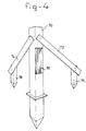
- Figure 4 shows an embodiment of a laser reflector.
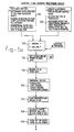
- Figures 5A...5E show a flow chart of the way in which the system functions during operation.
- Figure 5F shows how Figures 5A...5E are related to one another.
- Figure 6 shows an embodiment of the system according to the invention with which neither the processor nor the laser transmitter/receiver are located on the vehicle.
- FIG. 1 shows a mobile pile driving rig, which is indicated in its entirety by 10.
- the pile driving rig is provided with a cabin 12, a generator unit 14 and a ballast block 15, which are positioned together on a frame 16.
- the frame 16 Via a pivot bearing 18, the frame 16 is positioned on a subframe 20 which can be moved by means of the caterpillar tracks 22.
- One end of an extending table 24 is mounted on the frame 16 such that it is able to rotate, whilst the other end of the extending table 24 is fixed via hinge 25 to the vertical pile guide 26, only part of which can be seen in the Figure. Part of a pile 28 can be seen next to the pile guide 26.
- the pile driving rig is first driven on the caterpillar tracks 22 to the desired location.
- the vertical guide 26 is then manoeuvred into the desired position by, if necessary, turning the frame 16 with the aid of the bogie 18 and/or by sliding the extending table 24 further in or out.
- the pile guide 26 is then supported on its foot 30 and the entire rig is also fixed by means of one or more stabiliser legs, one of which, indicated by 32, can be seen in Figure 1 at the rear of the pile driving rig. Following this positioning manoeuvre, driving of the pile 28 can start.
- the position of the locations where the piles have to be introduced is determined by measurements with respect to a number of guide pegs, the position of which is determined with the aid of known measuring methods. Errors can be made when setting out the guide pegs. More significantly, however, the pegs can sometimes be dislodged after they have been set out and then put back by guesswork. Errors can also be made when positioning the pile with respect to the guide peg.
- the pile driving rig known per se is provided with a rotary laser transmitter/receiver 34 which, in the illustrative embodiment shown, is fixed via a supporting element 36 to the ballast block 15. Furthermore, the rig is provided with a first spirit level 38 and a second spirit level 40.
- the first spirit level 38 is used to measure any inclination of the pile driving rig in the transverse direction and in the longitudinal direction, whilst the second spirit level 40 is intended to measure any inclination of the extending table 24 in the longitudinal direction of the rig .
- the rig is also provided witn a length measuring device 42 with which the current length of the extending table is determined.
- the spirit levels 38 and 40 are of a type with which analog or digital signals can be generated, depending on the inclination detected. "Electronic" spirit levels of this type are known per se to those skilled in the art and therefore require no further discussion.
- the length measuring device 42 is also of a type with which analog or digital signals can be generated, depending on the length determined at the particular point in time.
- "Electronic" length measuring devices of this type for example in the form of electronic measuring tapes, are likewise known per se to those skilled in the art and therefore require no further detailed explanation.
- the rig is also provided with at least one temperature probe 41, which, for example, can be mounted on the extending table 24 and which is intended to measure the temperature of the extending table.
- the pile driving rig must be able to operate at substantially varying temperatures.
- the dimensions of various parts of the rig, such as the extending table 24, the frame 16 and the pile guide 26, are temperature-dependent, it is preferable, in connection with the target accuracy, also to have available information regarding the current temperature of the various parts of the pile driving rig.
- several temperature meters can be installed on various parts of the rig for this purpose.
- the laser transmitter/receiver 34 can, for example be of a type which is described in detail in US patent 5,076,690, which has already been mentioned above. With the aid of said laser transmitter/receiver 34 it is possible accurately to determine the location of the transmitter/receiver with respect to a number of reflectors which are located around the building site. Not only the location can be accurately determined; the angular position with respect to an imaginary reference line which is determined by the positions of the various reflectors can also be established; in other words the direction of the longitudinal axis of the pile driving rig as a whole can be determined with the aid of the laser transmitter/receiver.
- the information regarding position which is generated in the laser transmitter/receiver 34 is supplied to a computer 44, which in Figure 1 is located in a separate housing on top of the generator unit 14. Said computer could also be set up in the cabin or in another suitable location.
- the signals from the first spirit level 38, the second spirit level 40, the optional temperature probes 41 and the length measuring device 42 are also supplied to said computer
- a display panel 48 and an input unit 46 for example in the form of a joystick, tracker ball or something similar, which is to be operated by the pile driving rig operator, are located in the cabin 12 of the pile driving rig. Neither can be seen in Figure 1 but both are shown diagrammatically in Figure 2.
- Figure 2 shows, in the form of a block diagram, the means which form part of a preferred embodiment of a system according to the invention.
- the computer 44 receives data regarding the coordinates X, Y and Z relating to the actual position of the laser transmitter/receiver 34 from said laser transmitter/receiver.
- the spirit level 38 supplies data with regard to any angle of inclination in the longitudinal direction of the frame 16 and the direction perpendicular thereto, and the spirit level 40 supplies data with regard to any inclination of the extending table 24 in the lengthwise direction of the pile driving rig 10.
- the length measuring device 42 supplies data with regard to the current length L of the extending table 24.
- a keyboard 43 can be connected to the processor, which keyboard can be used, for example, to program the processor.
- the processor could be coupled to a floppy disk memory, a hard disk memory or another memory medium for mass storage. In view of the fairly harsh environment in which the processor has to carry out its task, it is, however, preferable as far as possible to restrict the number of peripherals during operation.
- data relating to a number of additional fixed dimensions of the rig are stored in the memory of the computer. These dimensions have to be entered and stored in the memory once, when the system is installed. If present, the temperature probes 41 then supply data relating to the current temperature of one or more parts of the rig for which the accurate dimensions are temperature-dependent and therefore can be affected.
- the laser transmitter/receiver 34 continuously determines its own position with respect to the various reflectors. In this operation, in particular the angle with respect to each of the reflectors is determined and the X, Y and Z coordinates of the current position of the laser transmitter/receiver 34 are determined immediately from the combination of incoming signals. These data are read out by the computer 44 and entered into a drawing program, such as, for example, AutoCad. With the aid of this drawing program, as is still to be discussed below, a plan of the entire building site is drawn on the screen 48 in the cabin 12 and the position of the pile driving rig 10 is indicated on said plan on the basis of the X and Y coordinates measured by the laser transmitter/receiver 34.
- a drawing program such as, for example, AutoCad.
- Figure 3a shows, diagrammatically, an example of the way in which the position data can be displayed to the pile driving rig operator.
- a plan of the entire building site with the laser reflectors located on the site individually marked is first shown on the screen 50 of the display unit 48.
- said laser reflectors are indicated as small rectangles 52a, 52b....52x. If a sufficiently large number of reflectors is used, the laser transmitter 34 is then not only capable of determining its own position with respect to the reflectors, but the position of every reflector with respect to the other reflectors can also be determined, assuming that at least a few reference data are known. Should a reflector be removed from its position temporarily, the new position can be "calibrated" easily when the reflector is replaced.
- the laser transmitter/receiver 34 not only calculates the current X and Y coordinates of its own position, but also calculates the direction of the longitudinal axis of the pile driving rig. It is therefore possible to show the pile driving rig on the screen display in the form of a symbol which shows which is the front and the rear of the pile driving rig and at which point the pile guide 26 or the pile 28 is located. Such a symbol 54 is shown on the screen 50 in Figure 3a by way of example.
- the locations in which piles have to be placed are also indicated on the screen by means of suitable indicators, for example crosses 56a, 56b....56x.
- the crane driver therefore sees on the screen the desired position for the piles still to be placed and, on the other hand, the current position of the pile driving rig.
- the operator selects the pile he wishes to place in position.
- the operator now drives the rig 10 to the position where the next pile has to be driven.
- the software which is loaded in the computer 44 preferably functions in such a way that it automatically zooms in on the image on the screen when the selected position is approached.
- the measured values generated by the spirit levels 38 and 40, by the length measuring device 42 and by any temperature probes 41 which are present, now also start to play an important role.
- the measured values transmitted by said sensors are also supplied to the computer 44 and processed therein together with the signal from the laser transmitter/receiver 34 in order to calculate the precise location of the centre of the foot of the pile 28 in the rig.
- Said calculated centre position of the pile 28 is, for example, displayed on the screen as a circle 58 at the end of the symbol indicating the extending table 60, in the manner shown in Figure 3b.
- the desired position where the new pile has to be driven is shown, for example, as a sighting cross 62. The operator must now ensure that the sighting cross is brought into line with the pile circle 58.
- the pile driving rig is fixed by means of the stabiliser legs 32 or, optionally, other means present for this purpose and the next pile 28 is driven.
- the operator uses the joystick 46 to report this to the computer 44, which then labels the pile in the program as "present” and changes the marking for the pile concerned in such a way that this fact is clear to the observer, for example in the manner which is shown at 64 on the screen in Figure 3c.
- the final position of the pile is now logged, as a result of which any deviation from the planned position has been established.
- the operator After installation of the pile, the operator selects a new pile and drives the rig in the direction of the new pile position. As soon as the rig is within a sufficiently short distance, the computer automatically zooms in again on the screen and the operator is able to bring the new pile 28 accurately above the desired position. Following installation, this pile also is labelled as "present” and the operator can continue with the next pile.
- the laser transmitter/receiver 34 would have to have a 360° field of view. Moreover, the unit 34 must always be horizontal, irrespective of any inclination of the pile driving rig itself. An uninterrupted 360° field of view would demand that the laser transmitter/receiver has to be placed on top of the hanging post at the top of the pile guide 26. Although such a position is one of the possibilities, it is not very handy in practice. Therefore, in a practical set-up, a position has been chosen on a corner at the rear of the rig, as is illustrated in Figure 1. In this position, the unit 34 had a field of view of 270° and in combination with a sufficient number of reflectors around the boundary of the site it proved to be possible with this arrangement to be able to determine the position of the unit 34 with the desired accuracy.
- Cardan mounting mechanisms of this type are known per se and a detailed description thereof is therefore also considered superfluous in the context of the invention.
- the reflectors which are located around the boundary of the site preferably consist of posts which are placed vertically in the ground.
- Figure 4 shows an example in which the actual reflector post 70 can be positioned vertically with the aid of two props 72 and 74 and two guide pegs 76 and 78 in a manner such as is customary in the building world.
- Reflecting material 80 is present on the post 70, which reflecting material is applied as vertical strips parallel to one another, in such a way that a coded reflection signal is received during scanning by the horizontally rotating laser beam.
- the laser transmitter/receiver 34 is mounted in the manner shown in Figure 1 such that it does not have a complete 360° field of view. Practical trials have shown that it is preferable to arrange the reflectors such that, if the laser transmitter/receiver should be located approximately in the middle of the building site, one reflector is visible about every 30°. In other words, if the building site is regarded as circular, it is preferable to place 12 reflectors approximately equal distances apart around the boundary of the building site. Under all circumstances, the laser transmitter/receiver 34 then has an adequate number of reflectors within its field of view to be able to establish the position of the pile 28 with the desired accuracy.
- a number of fixed data per building site are recorded. This relates to the determination of the two-dimensional or three-dimensional axial plot of the building site from a number of reference points, reading-in of the building site plan, designated BSP below, together with the piling plan, and also all data relating to the piles, and a transformation of the two-dimensional or three-dimensional axial plot of the building site into the two-dimensional or three-dimensional axial plot of the building site plan.
- Block 102 indicates which fixed data relating to the rig used have to be known to the system. These data relate to the type of machine and the pile guide or hanging post, the location and the type of the laser transmitter/receiver and a specification of the dimensions which are needed for transformations of coordinates from the transmitter/receiver to the centre of the pile/drill with the level plane of the excavation.
- the operator of the pile driving rig has to choose between driving or drilling. Where the data have to be stored and/or retrieved from is then determined in block 104 and subsequently, in block 105, the chosen medium is used to actually store or retrieve all data relating to the building site and the pile driving rig.
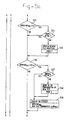
- the current position of the rig is determined and in block 108 the position of the centre of the pile/drill, which is carried by the rig, on the level plane of the excavation is calculated.
- the building site plan BSP is displayed on the screen and the current position of the rig is also shown on this plan.
- the question is posed as to whether the pile position concerned is a new pile position or not. If it is not a new pile position, the procedure continues at block 120; and if it is a new pile position, the procedure continues at block 111. In the last-mentioned block a check is made to establish whether the display on the screen is adequate or not. If the display on the screen is adequate, a new pile position must then be selected in block 112, and in block 113 a check is made to establish whether this selection has in fact been made. If not, the program loops back to block 112 until such time as the new pile position has been marked. As soon as this has been done, action is taken in block 118 to mark the selected pile position on the screen.
- zooming-in is first activated in block 114, after which the pile position must then be selected in the loop in which blocks 115 and 116 are incorporated. Then, in block 117, the screen display is first returned to normal by zooming out, after which, in block 118, the pile selected via this route is marked on the screen.
- the current position of the centre of the pile or of the drill with respect to the level plane of the excavation is calculated and, in addition, the distance between said centre and the new pile position is calculated.
- the display is gradually zoomed in in such a way that the operator of the pile driving rig is able, on the basis of the image which is displayed on the screen, accurately to position the rig at the desired new pile position.
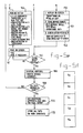
- Block 130 in which a check is made to determine whether the distance away from the new pile position is greater or smaller than 25 metres, is at the start of this zooming-in procedure. If the distance is less than 25 metres, a check is made in block 131 to determine whether the first zooming position "zoom 0" has already been activated. If this is not the case, said zoom position is activated in block 132. Subsequently, a similar process is carried out in blocks 133, 134 and 135, checks now being made to determine whether the distance away from the new pile position is less than 1 metre and, if this is the case, the next zoom position "zoom 1" is then activated if necessary. This process is repeated again in blocks 136, 137 and 138. The distance between the position of the centre of the pile and the new pile position is now less than 30 cm and, to assist the operator of the rig, the coordinates of the new pile position and the distance which still has to be travelled to reach said position are now displayed on the screen.
- the question in block 140 will be answered by "yes”.
- the system pauses until an answer is given by the operator. If the operator elects to start the driving process, this will be displayed on the screen in block 144.
- the procedure continues to cycle in the blocks 145, 146 and 147. As long as the driving process is active, this loop is followed until the operator indicates that the process is complete. In this case, the question in block 147 is answered by "yes" and the process will continue with the combination of blocks 150, 151 and 152.
- block 150 a marker will be displayed on the screen which indicates that the driving process at the location concerned is complete.
- block 151 it is ensured that the data for the pile which has just been driven are stored on an information carrier, such as the IBD, and in block 152 it is ensured that the display on the screen is restored to the initial position, in other words the display is zoomed out again to the full extent such that the complete building site plan can be seen on the screen again.
- block 160 the question is posed as to whether the driving process for the new pile position has been carried out.
- the answer in this block is "no" during the phase in which the operator is engaged in moving the pile driving rig to the new position, the distance between the centre of the pile and the new position not yet having become smaller than 5 cm.
- the process continues with block 161, in which measures are taken for ongoing correction of the position of the rig on the screen.
- block 162 a readout is given of all current measurement data from the laser transmitter/receiver, from the various spirit levels and from the length measuring device, on the basis of which, in block 120, the new current position can then be calculated.
- Block 163 If temperature probes are present, the values from these are read out in block 163. In order to prevent very small and minor corrections having to be made every time, said temperature data are read out only at preset intervals, for example at an interval of 15 minutes. Block 164, in which a check is made to determine whether the relevant interval has elapsed, serves for this purpose.
- block 160 If the question in block 160 is answered by "yes", the operator, or some other person, has a facility, in block 166, for appending any remarks or further comments to the stored data. Subsequently, a check is made in block 168 that all piles have been driven. If not, the process returns to block 110. If all piles have been driven, block 170 offers the facility for appending any concluding remarks to the data and thereafter, in block 172, all data are stored.
- Figure 6 shows, diagrammatically, a plan of a site on which six laser reflectors 200A, 200B...200F are positioned.
- the laser transmitter/receiver 202 and the mobile pile driving rig 203 are also located on the site.
- the mobile pile driving rig 203 is provided with a laser reflector 201 and is also provided with a radio transmitter 204, which is coupled to the various sensors, such as the spirit levels, length measuring device, temperature sensors and the like, which are not shown individually in the figure.
- a processor 205 which is coupled to an indicator unit or display panel 208, is also present on the site.
- the data relating to position, which are collected by the laser transmitter/receiver 202, are transferred to the processor 205 via a communication link 206, for example a radio link and/or light link and/or cable connection.
- a further communication link 207 for example a radio link and/or light link, the data measured by the various sensors are transferred by means of the transmitter/receiver 204 on the pile driving rig 203 to the processor 205.
- a further indicator unit or display panel 208' (not shown in the figure) to be located in the operator's cabin, which unit has the same function as indicator unit 208 and, as it were, is coupled thereto.
- the communication link 207 to transmitter/receiver 204 can also be used for the communication with said indicator unit 208', which is located on or in the vehicle.
- the laser transmitter/receiver can be moved if appropriate, if this is desirable in connection with the building work or the further developments on the site. After moving to a new location, it is necessary merely to determine once again the new position of the laser transmitter/receiver with respect to the reflectors 200A...200F in a separate calibration procedure, after which the entire system can again be used for further positioning of the vehicle. The positioning of the vehicle can then again be carried out by staff who have the requisite data available in the cabin of the vehicle.
Landscapes
- Physics & Mathematics (AREA)
- Engineering & Computer Science (AREA)
- General Physics & Mathematics (AREA)
- Radar, Positioning & Navigation (AREA)
- Remote Sensing (AREA)
- Electromagnetism (AREA)
- Aviation & Aerospace Engineering (AREA)
- Automation & Control Theory (AREA)
- Optics & Photonics (AREA)
- Length Measuring Devices By Optical Means (AREA)
Claims (22)
- System zum Positionieren eines Arbeiten ausführenden Gerätes innerhalb eines vordefinierten Gebiets, wobei das Arbeiten ausführende Gerät mit dem Rahmen eines Fahrzeugs über eine Anzahl beweglicher Teile verbunden ist, wobei das System ausgestattet ist mitdadurch gekennzeichnet, daßeiner Anzahl von auf dem Fahrzeug und/oder den beweglichen Teilen installierten Sensoren, um die wechselseitigen Stellungen der beweglichen Teile zu überwachen,einem Prozessor zum Empfang von Signalen von den Sensoren und zur Berechnung des Standorts dieses Arbeiten ausführenden Geräts in Bezug auf einen Referenzpunkt auf dem Fahrzeug,einem Laser-Subsystem zur Überwachung der Stellung des Fahrzeugs in Relation zu einer Bezugstelle in der Umgebung,der Laser-Subsystem einen Laser-Sender, der einen routierenden Strahl in einer horizontalen Ebene aussendet, einen mit diesem Laser-Sender kombinierten Laser-Empfänger und mindestens drei an Stellungen in oder um das vordefinierte Gebiet angeordnete Laser-Reflektoren umfaßt, wobei einer dieser Reflektoren oder die Kombination aus Laser-Sender und Laser-Empfänger auf dem Bezugspunkt , auf dem Fahrzeug angeordnet ist,das System eine Kommunikationsverbindung zwischen dem Laser-Empfänger und dem Prozessor umfaßt, um Daten über die Stellung des Bezugspunkts in der horizontalen Ebene an den Prozessor zu übertragen,und daß der Prozessor die Stellungsdaten vom Laser-Empfänger empfängt und die genaue Stellung des Arbeiten ausführenden Geräts wenigstens in der horizontalen Ebene berechnet.
- System nach Anspruch 1. dadurch gekennzeichnet, daß das Fahrzeug am Bezugspunkt mit einem Laser-Reflektor versehen ist, und dadurch, daß der Laser-Sender/Empfänger an einer vordefinierten Stelle angeordnet ist, von der aus er in der Lage ist, Strahlung auf eine adäquate Zahl von Laser-Reflektoren zu richten, um in der Lage zu sein, aus den erhaltenen gemessenen Werten die Stellung des Laser-Reflektors auf den Bezugspunkt zu bestimmen.
- System nach Anspruch 1, dadurch gekennzeichnet, daß der Laser-Sender/Empfänger auf dem Bezugspunkt auf dem Fahrzeug lokalisiert ist.
- System nach einem der vorhergehenden Ansprüche, dadurch gekennzeichnet, daß die Kommunikationsverbindung zwischen den Sensoren auf dem Fahrzeug und dem Prozessor zur Übertragung der gemessenen Werte von den Sensoren auf dem Prozessor durch einen drahtlosen Kommunikationsweg gebildet ist.
- System nach einem der vorhergehenden Ansprüche, dadurch gekennzeichnet, daß die Kommunikationsverbindung zwischen dem Laser-Sender/-Empfänger und dem Prozessor durch einen drahtlosen Kommunikationsweg gebildet ist.
- System nach einem der vorhergehenden Ansprüche, dadurch gekennzeichnet, daß der Prozessor auf dem Fahrzeug angeordnet ist.
- System nach einem der vorhergehenden Ansprüche, dadurch gekennzeichnet, daß das System mit einer Anzeige- oder Darstellungstafel versehen ist, die mit dem Prozessor über eine Kommunikationsverbindung verbunden ist und auf der Informationen in Bezug auf die spezifische Position des Ortes, wo die vordefinierte Arbeit ausgeführt werden soll, angezeigt werden kann, und ebenso eine oder mehrere spezifische Positionen angezeigt werden können, bevor die spezifische Arbeit begonnen wird.
- System nach einem der vorhergehenden Ansprüche, dadurch gekennzeichnet, daß die Kommunikationsverbindung zwischen dem Prozessor und der Indikatoreinheit durch einen drahtlosen Kommunikationsweg gebildet ist.
- System nach Anspruch 6, dadurch gekennzeichnet, daß die Anzeigetafel auf dem Fahrzeug angeordnet ist.
- System nach einem der vorhergehenden Ansprüche, dadurch gekennzeichnet, daß der Prozessor auch Informationen bezüglich der Stellung des Fahrzeuges als einem Ganzen auf der Basis der Ausgangssignale aus dem Laser-Sender/-Empfänger zur Verfügung stellt.
- System nach einem der vorhergehenden Ansprüche, dadurch gekennzeichnet, daß das Fahrzeug eine mobile Pfahlrammenrig-Einrichtung, Bohrrig-Einrichtung oder dgl. ist, mit der längliche Objekte wie Pfähle, Spundbohlenelemente, Schraubenpfähle, Rohre oder dgl. in den Boden eingeführt werden können.
- System nach Anspruch 11, dadurch gekennzeichnet, daß die Anzeigetafel als zweidimensionale Wiedergabetafel gestaltet ist, auf der die spezifische Position des Ortes, wo das längliche Objekt in den Boden einzuführen ist und/oder die Position des Fahrzeugs als Ganzes als eine Markierung wiedergegeben ist, die von einem Plan des vordefinierten Gebiets überlagert ist.
- System nach Anspruch 12, dadurch gekennzeichnet, daß Mittel vorhanden sind. um wenigstens eine vordefinierte gewünschte Position auf dem Plan, der auf der Anzeigetafel gezeigt wird, zu markieren.
- System nach Anspruch 13, gekennzeichnet dadurch, daß Mittel zur Veränderung auf dem Plan der Anzeigetafel in solchem Ausmaß vorhanden sind, daß es für den Fahrzeugführer möglich wird, durch Beeinflussung des Fahrzeugs und/oder der genannten Teile, die die Positionen, an denen die länglichen Objekte in den Boden eingeführt werden sollen, bestimmen, die gewünschte Position in Übereinstimmung mit der vordefinierten Position innerhalb vorgegebener Toleranzen zu bringen.
- System nach einem der vorhergehenden Ansprüche, dadurch gekennzeichnet, daß Mittel vorhanden sind, um, nachdem die länglichen Objekte in den Boden eingeführt worden sind, eine Markierung auf dem Bildschirm anzubringen, der anzeigt, daß ein längliches Objekt in den Boden an der betroffenen Stelle eingeführt wurde.
- System nach einem der vorhergehenden Ansprüche, dadurch gekennzeichnet, daß der Laser-Sender/-Empfänger in einem Cardan-Gehäuse in der Weise angebracht ist, daß der Sender immer in einer horizontalen Ebene unabhängig von jeder Neigung der Stellung des Fahrzeugs arbeitet.
- System nach einem der vorhergehenden Ansprüche, dadurch gekennzeichnet, daß das Fahrzeug mit Detektoren für die Winkelstellung versehen ist, mit denen die Winkelstellung oder Neigung des Fahrzeugs gegen die horizontale Ebene in mindestens zwei zueinander senkrechten horizontalen Ebenen bestimmt wird.
- System nach einem der vorhergehenden Ansprüche, dadurch gekennzeichnet, daß der Laser-Sender/-Empfänger auf der Spitze oder in einer relativ großen Entfernung von den Führungen für die länglichen Objekte angeordnet ist, so daß der Laser-Sender/-Empfänger einen Blickwinkel von mindestens 180° und vorzugsweise von mindestens ungefähr 270° hat, und daß die Zahl der Laser-Reflektoren und deren Stellung so gewählt ist, daß der Laser-Sender/-Empfänger in der Lage ist, die Position des Fahrzeugs mit ausreichender Genauigkeit in jeder Stellung innerhalb des Gebiet und in jeder Position des Fahrzeugs zu bestimmen.
- System nach einem der vorhergehenden Ansprüche, dadurch gekennzeichnet, daß das Fahrzeug mit Detektoren ausgestattet ist, mit denen jede Winkelposition der Führungen für die länglichen Objekte in Bezug auf die Vertikale bestimmt werden kann.
- System nach einem der vorhergehenden Ansprüche, dadurch gekennzeichnet, daß die Zahl der Laser-Fleflektoren wenigstens eine höher als die Mindestzahl, die theoretisch erforderlich ist, um die Position des Fahrzeugs zu bestimmen, ist.
- System nach einem der vorhergehenden Ansprüche, dadurch gekennzeichnet, daß das System mit einem Speicher versehen ist, in dem die Daten in Bezug auf eine Zahl spezifischer Stellungen, wo ein längliches Objekt in den Boden eingeführt wurde, gespeichert werden können.
- System nach Anspruch 19, dadurch gekennzeichnet, daß nach der Einführung eines länglichen Objekts dessen Stellung noch einmal berechnet wird und die aus dieser Berechnung resultierenden Daten in dem Speicher gespeichert werden.
Applications Claiming Priority (2)
| Application Number | Priority Date | Filing Date | Title |
|---|---|---|---|
| NL9301864 | 1993-10-28 | ||
| NL9301864A NL9301864A (nl) | 1993-10-28 | 1993-10-28 | Stelsel voor het positioneren van een heistelling of soortgelijke inrichting. |
Publications (2)
| Publication Number | Publication Date |
|---|---|
| EP0651305A1 EP0651305A1 (de) | 1995-05-03 |
| EP0651305B1 true EP0651305B1 (de) | 1998-01-21 |
Family
ID=19863063
Family Applications (1)
| Application Number | Title | Priority Date | Filing Date |
|---|---|---|---|
| EP94203131A Expired - Lifetime EP0651305B1 (de) | 1993-10-28 | 1994-10-27 | System zur Positionierung einer Pfahlrammenriggeinrichtung oder dergleichen |
Country Status (4)
| Country | Link |
|---|---|
| US (1) | US5548397A (de) |
| EP (1) | EP0651305B1 (de) |
| DE (1) | DE69408086D1 (de) |
| NL (1) | NL9301864A (de) |
Families Citing this family (23)
| Publication number | Priority date | Publication date | Assignee | Title |
|---|---|---|---|---|
| US5610818A (en) * | 1995-11-22 | 1997-03-11 | Trimble Navigation Limited | Remote operated computer assisted precise pile driving and rig drilling system |
| US5771978A (en) * | 1996-06-05 | 1998-06-30 | Kabushiki Kaisha Topcon | Grading implement elevation controller with tracking station and reference laser beam |
| US5978749A (en) * | 1997-06-30 | 1999-11-02 | Pile Dynamics, Inc. | Pile installation recording system |
| US6301551B1 (en) * | 1998-10-01 | 2001-10-09 | Pile Dynamics, Inc. | Remote pile driving analyzer |
| US6600553B1 (en) * | 1998-11-03 | 2003-07-29 | National Institute Of Science And Technology U.S. Dept Of Commerce | Three degree-of-freedom telescoping geometry scanner |
| CA2466862C (en) * | 2003-05-12 | 2011-07-26 | Bermingham Construction Limited | Pile driver with energy monitoring and control circuit |
| US7404449B2 (en) * | 2003-05-12 | 2008-07-29 | Bermingham Construction Limited | Pile driving control apparatus and pile driving system |
| US9747698B2 (en) * | 2006-10-21 | 2017-08-29 | Sam Stathis | System for accurately and precisely locating and marking a position in space using wireless communications and robotics |
| US9858712B2 (en) * | 2007-04-09 | 2018-01-02 | Sam Stathis | System and method capable of navigating and/or mapping any multi-dimensional space |
| US8063349B2 (en) | 2007-04-15 | 2011-11-22 | Brightsource Industries (Israel) Ltd. | Heliostats and solar concentration systems employing heliostats |
| WO2010129944A2 (en) * | 2009-05-08 | 2010-11-11 | Sandvik Mining And Construction Usa, Llc | Method and system for integrating sensors on an autonomous mining drilling rig |
| US8983707B2 (en) | 2010-11-30 | 2015-03-17 | Caterpillar Inc. | Machine control system having autonomous dump queuing |
| US8684632B2 (en) | 2010-12-08 | 2014-04-01 | Laserline Mfg., Inc. | Systems and methods for laying out and installing a solar panel array |
| US10162797B1 (en) * | 2012-04-13 | 2018-12-25 | Design Data Corporation | System for determining structural member liftability |
| DE102013000463A1 (de) * | 2013-01-03 | 2014-07-03 | Terex Cranes Germany Gmbh | Mobiles Arbeitsgerät, insbesondere Mobilkran |
| CA2801185C (en) * | 2013-01-05 | 2018-01-02 | Wayne Mcilravey | Load cell for screw piling power head |
| US20140190275A1 (en) | 2013-01-05 | 2014-07-10 | Concept Torque Solutions Inc. | Load Cell for Screw Pililng Power Head |
| US8848180B1 (en) | 2013-09-05 | 2014-09-30 | Laserline Mfg., Inc. | Reference systems for indicating slope and alignment and related devices, systems, and methods |
| AU2014342114B2 (en) * | 2013-11-01 | 2019-06-20 | Irobot Corporation | Scanning range finder |
| CN109403946B (zh) * | 2018-12-27 | 2022-07-29 | 北京三一智造科技有限公司 | 旋挖钻机回转动画显示的方法、装置及旋挖钻机 |
| US10590757B1 (en) | 2019-04-09 | 2020-03-17 | Erdos Miller, Inc. | Measurement while drilling communication scheme |
| US11788247B1 (en) * | 2022-12-21 | 2023-10-17 | Built Robotics Inc. | Basket assembly operation for autonomous pile driving system |
| US11822342B1 (en) | 2022-12-21 | 2023-11-21 | Built Robotics Inc. | Obstacle map for autonomous pile driving system |
Citations (1)
| Publication number | Priority date | Publication date | Assignee | Title |
|---|---|---|---|---|
| EP0188623A1 (de) * | 1984-07-12 | 1986-07-30 | Fanuc Ltd. | Verfahren zum einstellen der werkzeugkoordinaten |
Family Cites Families (14)
| Publication number | Priority date | Publication date | Assignee | Title |
|---|---|---|---|---|
| CH599536A5 (de) * | 1975-09-02 | 1978-05-31 | Kern & Co Ag | |
| US4225226A (en) * | 1978-12-29 | 1980-09-30 | Spectra-Physics, Inc. | Laser guidance system for crop spraying aircraft |
| US4835692A (en) * | 1986-02-05 | 1989-05-30 | Bridge & Plate Construction Pty. Ltd. | Remote controlled travel apparatus |
| US4830489A (en) * | 1986-08-20 | 1989-05-16 | Spectra-Physics, Inc. | Three dimensional laser beam survey system |
| US4796198A (en) * | 1986-10-17 | 1989-01-03 | The United States Of America As Represented By The United States Department Of Energy | Method for laser-based two-dimensional navigation system in a structured environment |
| US4805086A (en) * | 1987-04-24 | 1989-02-14 | Laser Alignment, Inc. | Apparatus and method for controlling a hydraulic excavator |
| US4790402A (en) * | 1987-09-28 | 1988-12-13 | Tennant Company | Automated guided vehicle |
| US4936678A (en) * | 1988-03-21 | 1990-06-26 | The Ohio State University | Position detection system for use with agricultural and construction equipment |
| US5100229A (en) * | 1990-08-17 | 1992-03-31 | Spatial Positioning Systems, Inc. | Spatial positioning system |
| US5461473A (en) * | 1990-12-31 | 1995-10-24 | Spatial Positioning Systems, Inc. | Transmitter and receiver units for spatial position measurement system |
| FR2671625B1 (fr) * | 1991-01-16 | 1995-01-06 | Maurice Tosi | Dispositif de determination de la position de l'outil d'un engin de travail. |
| US5301005A (en) * | 1993-02-10 | 1994-04-05 | Spectra-Physics Laserplane, Inc. | Method and apparatus for determining the position of a retroreflective element |
| US5416321A (en) * | 1993-04-08 | 1995-05-16 | Coleman Research Corporation | Integrated apparatus for mapping and characterizing the chemical composition of surfaces |
| US5367458A (en) * | 1993-08-10 | 1994-11-22 | Caterpillar Industrial Inc. | Apparatus and method for identifying scanned reflective anonymous targets |
-
1993
- 1993-10-28 NL NL9301864A patent/NL9301864A/nl not_active Application Discontinuation
-
1994
- 1994-10-27 EP EP94203131A patent/EP0651305B1/de not_active Expired - Lifetime
- 1994-10-27 DE DE69408086T patent/DE69408086D1/de not_active Expired - Lifetime
- 1994-10-28 US US08/331,172 patent/US5548397A/en not_active Expired - Fee Related
Patent Citations (1)
| Publication number | Priority date | Publication date | Assignee | Title |
|---|---|---|---|---|
| EP0188623A1 (de) * | 1984-07-12 | 1986-07-30 | Fanuc Ltd. | Verfahren zum einstellen der werkzeugkoordinaten |
Also Published As
| Publication number | Publication date |
|---|---|
| DE69408086D1 (de) | 1998-02-26 |
| US5548397A (en) | 1996-08-20 |
| EP0651305A1 (de) | 1995-05-03 |
| NL9301864A (nl) | 1995-05-16 |
Similar Documents
| Publication | Publication Date | Title |
|---|---|---|
| EP0651305B1 (de) | System zur Positionierung einer Pfahlrammenriggeinrichtung oder dergleichen | |
| US7139662B2 (en) | Device and method for determining the position of a working part | |
| US8122974B2 (en) | Apparatus for drilling machine alignment | |
| JP3645568B2 (ja) | 作業場所に対して地形変更マシンを操作する方法と装置 | |
| US9453729B2 (en) | Layout equipment and layout method | |
| AU767738B2 (en) | Real-time surveying/earth moving system | |
| RU2134329C1 (ru) | Устройство для определения местоположения копающего приспособления (варианты) и способ определения местоположения рабочей машины на рабочей площадке (варианты) | |
| US4820041A (en) | Position sensing system for surveying and grading | |
| US6421627B1 (en) | Device and method for determining the position of a working part | |
| US6381006B1 (en) | Spatial positioning | |
| JPH11508336A (ja) | 切削勾配制御装置 | |
| JP2866289B2 (ja) | 建設機械の位置及び姿勢表示方法 | |
| WO2005028999A2 (en) | Measurement methods and apparatus | |
| JPH1047961A (ja) | 制御システム及び制御方法 | |
| JP6285276B2 (ja) | 地表の放射線計測装置とその装置を用いた放射線計測方法 | |
| US6966387B2 (en) | Universal optical adapter for a three dimensional earthgrading system | |
| JP2856206B2 (ja) | 水中捨石均し装置 | |
| JP3383298B2 (ja) | 削岩装置における送りビーム整列方法および削岩装置および測定装置 | |
| JP4175727B2 (ja) | 自由断面掘削機に於ける掘削ブームの俯仰角及び旋回角検出方法 | |
| JP2913512B2 (ja) | 測量情報の送受信ターゲット | |
| CA2637906C (en) | Apparatus for drilling machine alignment | |
| JP2000329553A (ja) | 計測装置 | |
| JP4422927B2 (ja) | 土木工事における測量方法 | |
| JP4024422B2 (ja) | 自由断面掘削機に於ける切削ドラムのnc制御精度確認方法 | |
| JP4029953B2 (ja) | 自由断面掘削機に於ける過掘り防止装置の精度確認方法 |
Legal Events
| Date | Code | Title | Description |
|---|---|---|---|
| PUAI | Public reference made under article 153(3) epc to a published international application that has entered the european phase |
Free format text: ORIGINAL CODE: 0009012 |
|
| AK | Designated contracting states |
Kind code of ref document: A1 Designated state(s): BE DE FR GB IT LU NL |
|
| 17P | Request for examination filed |
Effective date: 19950824 |
|
| 17Q | First examination report despatched |
Effective date: 19960819 |
|
| GRAG | Despatch of communication of intention to grant |
Free format text: ORIGINAL CODE: EPIDOS AGRA |
|
| GRAG | Despatch of communication of intention to grant |
Free format text: ORIGINAL CODE: EPIDOS AGRA |
|
| GRAH | Despatch of communication of intention to grant a patent |
Free format text: ORIGINAL CODE: EPIDOS IGRA |
|
| GRAH | Despatch of communication of intention to grant a patent |
Free format text: ORIGINAL CODE: EPIDOS IGRA |
|
| GRAA | (expected) grant |
Free format text: ORIGINAL CODE: 0009210 |
|
| AK | Designated contracting states |
Kind code of ref document: B1 Designated state(s): BE DE FR GB IT LU NL |
|
| PG25 | Lapsed in a contracting state [announced via postgrant information from national office to epo] |
Ref country code: NL Free format text: LAPSE BECAUSE OF FAILURE TO SUBMIT A TRANSLATION OF THE DESCRIPTION OR TO PAY THE FEE WITHIN THE PRESCRIBED TIME-LIMIT Effective date: 19980121 Ref country code: IT Free format text: LAPSE BECAUSE OF FAILURE TO SUBMIT A TRANSLATION OF THE DESCRIPTION OR TO PAY THE FEE WITHIN THE PRE;WARNING: LAPSES OF ITALIAN PATENTS WITH EFFECTIVE DATE BEFORE 2007 MAY HAVE OCCURRED AT ANY TIME BEFORE 2007. THE CORRECT EFFECTIVE DATE MAY BE DIFFERENT FROM THE ONE RECORDED.SCRIBED TIME-LIMIT Effective date: 19980121 Ref country code: FR Free format text: LAPSE BECAUSE OF FAILURE TO SUBMIT A TRANSLATION OF THE DESCRIPTION OR TO PAY THE FEE WITHIN THE PRESCRIBED TIME-LIMIT Effective date: 19980121 Ref country code: BE Free format text: LAPSE BECAUSE OF FAILURE TO SUBMIT A TRANSLATION OF THE DESCRIPTION OR TO PAY THE FEE WITHIN THE PRESCRIBED TIME-LIMIT Effective date: 19980121 |
|
| REF | Corresponds to: |
Ref document number: 69408086 Country of ref document: DE Date of ref document: 19980226 |
|
| PG25 | Lapsed in a contracting state [announced via postgrant information from national office to epo] |
Ref country code: DE Free format text: LAPSE BECAUSE OF FAILURE TO SUBMIT A TRANSLATION OF THE DESCRIPTION OR TO PAY THE FEE WITHIN THE PRESCRIBED TIME-LIMIT Effective date: 19980422 |
|
| EN | Fr: translation not filed | ||
| NLV1 | Nl: lapsed or annulled due to failure to fulfill the requirements of art. 29p and 29m of the patents act | ||
| PG25 | Lapsed in a contracting state [announced via postgrant information from national office to epo] |
Ref country code: LU Free format text: LAPSE BECAUSE OF NON-PAYMENT OF DUE FEES Effective date: 19981027 Ref country code: GB Free format text: LAPSE BECAUSE OF NON-PAYMENT OF DUE FEES Effective date: 19981027 |
|
| PLBE | No opposition filed within time limit |
Free format text: ORIGINAL CODE: 0009261 |
|
| STAA | Information on the status of an ep patent application or granted ep patent |
Free format text: STATUS: NO OPPOSITION FILED WITHIN TIME LIMIT |
|
| 26N | No opposition filed | ||
| GBPC | Gb: european patent ceased through non-payment of renewal fee |
Effective date: 19981027 |