EP0650554B1 - Verfahren zum betreiben einer gasturbine - Google Patents
Verfahren zum betreiben einer gasturbine Download PDFInfo
- Publication number
- EP0650554B1 EP0650554B1 EP93915904A EP93915904A EP0650554B1 EP 0650554 B1 EP0650554 B1 EP 0650554B1 EP 93915904 A EP93915904 A EP 93915904A EP 93915904 A EP93915904 A EP 93915904A EP 0650554 B1 EP0650554 B1 EP 0650554B1
- Authority
- EP
- European Patent Office
- Prior art keywords
- steam
- turbine
- gas
- combustion chamber
- pressure
- Prior art date
- Legal status (The legal status is an assumption and is not a legal conclusion. Google has not performed a legal analysis and makes no representation as to the accuracy of the status listed.)
- Expired - Lifetime
Links
Images
Classifications
-
- F—MECHANICAL ENGINEERING; LIGHTING; HEATING; WEAPONS; BLASTING
- F02—COMBUSTION ENGINES; HOT-GAS OR COMBUSTION-PRODUCT ENGINE PLANTS
- F02C—GAS-TURBINE PLANTS; AIR INTAKES FOR JET-PROPULSION PLANTS; CONTROLLING FUEL SUPPLY IN AIR-BREATHING JET-PROPULSION PLANTS
- F02C6/00—Plural gas-turbine plants; Combinations of gas-turbine plants with other apparatus; Adaptations of gas-turbine plants for special use
- F02C6/003—Gas-turbine plants with heaters between turbine stages
-
- F—MECHANICAL ENGINEERING; LIGHTING; HEATING; WEAPONS; BLASTING
- F01—MACHINES OR ENGINES IN GENERAL; ENGINE PLANTS IN GENERAL; STEAM ENGINES
- F01K—STEAM ENGINE PLANTS; STEAM ACCUMULATORS; ENGINE PLANTS NOT OTHERWISE PROVIDED FOR; ENGINES USING SPECIAL WORKING FLUIDS OR CYCLES
- F01K21/00—Steam engine plants not otherwise provided for
- F01K21/04—Steam engine plants not otherwise provided for using mixtures of steam and gas; Plants generating or heating steam by bringing water or steam into direct contact with hot gas
- F01K21/047—Steam engine plants not otherwise provided for using mixtures of steam and gas; Plants generating or heating steam by bringing water or steam into direct contact with hot gas having at least one combustion gas turbine
-
- F—MECHANICAL ENGINEERING; LIGHTING; HEATING; WEAPONS; BLASTING
- F02—COMBUSTION ENGINES; HOT-GAS OR COMBUSTION-PRODUCT ENGINE PLANTS
- F02C—GAS-TURBINE PLANTS; AIR INTAKES FOR JET-PROPULSION PLANTS; CONTROLLING FUEL SUPPLY IN AIR-BREATHING JET-PROPULSION PLANTS
- F02C7/00—Features, components parts, details or accessories, not provided for in, or of interest apart form groups F02C1/00 - F02C6/00; Air intakes for jet-propulsion plants
- F02C7/12—Cooling of plants
- F02C7/16—Cooling of plants characterised by cooling medium
Definitions
- the invention relates to a method for operating a gas turbine according to the preamble of claim 1.
- thermodynamic mean temperature during the heat transfer of the process and thus the upper process temperature, the lower the exergy loss which limits the efficiency in the heat transfer between steam and flue gas.
- Common measures for increasing the thermodynamic mean temperature are reheating and regenerative feed water preheating.
- the gas turbine process allows a much higher upper process temperature, which is limited by the permissible turbine inlet temperature (today about 1000 to 1200 ° C). It is therefore necessary to select the excess air during combustion so high that the combustion chamber outlet temperature is reduced to the permissible turbine inlet temperature.
- a disadvantage of the gas turbine process is also the relatively high turbine outlet temperature, which causes the high lower process temperature of the gas turbine process.
- the efficiency of the pure gas turbine process can be increased by regenerative preheating of the combustion air by means of turbine exhaust gases and by intermediate heating in intermediate combustion chambers with a multi-stage arrangement of the gas turbine.
- the only heat source of this gas / steam power plant is the combustion chamber 3 of the gas turbine 1/2. If the system is started up (description, column 4, line 36 to column 5, line 44), the waste heat boiler 4 is the only steam source for the turbine 8 or the turbines 8 and 9 and for blowing steam into the combustion chamber. Since the amount of steam available for injection is limited, it follows that the amount of air required to cool the combustion chamber gases is still significantly above that required for combustion. The consequence of this is that the compressor output is significantly higher than the amount of air required to convey the stoichiometric amount. In EP-A-0 439 754, a steam accumulator is still connected to the steam process. However, this is only used for autonomous commissioning of a steam turbine of the steam cycle coupled to the gas turbine group. Continuous operation with the memory is not possible. A further coupling of the gas / steam power plant is not planned.
- Gas turbines are also known (FR-A-2 092 741 and GB-A-2 236145) in which the exhaust gases from the gas turbine are used to generate Water vapor can be used, which is added to cool the gas turbine process, for example into the combustion chamber.
- FR-A-2 092 741 such an amount of water can be added that the compressor output is only designed to convey the stoichiometrically required amount of air.
- these latter gas turbines are designed as individual systems and are not part of a steam process, although it is mentioned in GB-A-2 236 145 that steam can also be taken from an external source.
- the object of the invention is therefore to integrate a gas turbine into a steam process in such a way that optimum use is made of the steam of the steam process to increase the performance of a gas turbine and the waste heat of the gas turbine.
- the exhaust gas heat behind the turbine is used to generate water vapor, which is used in a separate steam process to generate shaft power in a steam turbine, the exhaust steam of the steam turbine being wholly or partly supplied to the combustion chamber gas after the reheat of the exhaust gas heat behind the gas turbine.
- the low-pressure steam from the steam source or from the waste heat boiler can also be fed to the reheater and overheated as far as possible before it is directed to the combustion chamber.
- the intermediate superheating reduces the steam generation in the waste heat boiler with the same flue gas waste heat flow and thus influences the performance of the gas turbine.
- the previously described method can be further improved if the thermodynamic The mean temperature of the steam side in connection with the exhaust gas heat behind the gas turbine is raised as far as possible.
- the steam power plant, steam process plant or steam heating system is simplified in that the gas turbine replaces a steam superheater or a low-pressure steam turbine.
- the water vapor can be injected into the combustion chamber gas in the area of the combustion chamber or in a connecting line between the combustion chamber and the turbine or in both. Such injection points are known per se.
- the gas turbine works with intermediate heating between a high-pressure turbine and a low-pressure turbine, the exhaust gas of the high-pressure turbine being heated up by heat transfer from the combustion chamber gas upstream of the high-pressure turbine, the average temperature of the gas turbine process is increased in an efficiency-increasing manner and the necessary cooling of the combustion chamber gases before entering the high-pressure turbine is partly by heat transfer from the exhaust gas, partly achieved by mixing with extraneous steam.
- the combustion chamber gas is cooled by heat transfer to water and water vapor before entering the turbine
- the water vapor being used in a separate steam process partial cooling of the combustion chamber gases can also be brought about by heat transfer in a single-stage gas turbine .
- the water vapor generated can be used in a separate steam power plant or as process or heating steam. It is advantageous that a separate steam boiler is not necessary.
- the steam generated in the waste heat boiler can be used externally and thus there is great flexibility in supplying steam consumers.
- the heat of condensation is achieved recover that can be used for heating purposes.
- a considerable part of the feed water is also generated, which is reused after suitable treatment.
- the preparation is particularly easy when using natural gas as fuel for the gas turbine. If no heat is required and the feed water is still to be recovered, the heat of condensation can be dissipated via any other heat sink, such as cooling towers or river water.
- waste heat boiler is arranged in the exhaust gas stream behind the turbine, which is in flow connection with the line or with a separate steam process, the waste heat from the gas turbine is used to generate water vapor, which is either added to the external water vapor for combustion chamber gas cooling or is used in the separate steam process .
- the steam heat exchanger is arranged in the combustion chamber gas flow between the combustion chamber and turbine, the inlet of which is in flow communication with the waste heat boiler and the outlet of which is in flow communication with an external water vapor consumer, high pressure steam can be generated in the waste heat boiler, which subsequently overheats in the steam heat exchanger and a high pressure steam process is supplied, wherein the fuel gas is cooled in front of the turbine.
- a condenser is arranged in the exhaust gas stream behind the waste heat boiler, the cooling system of which is in flow connection with a heat consumer, in particular a heating system, becomes cooling heat (Condensation heat) obtained at a low temperature level, such as is suitable for room heating.
- cooling heat Condensation heat
- Most of the feed water is also recovered by the arrangement according to the invention and returned to the steam process after treatment.
- FIGS. 1-4 show, as far as shown in detail, a gas turbine with an air compressor 4 and a turbine 5, the turbine 5 being in flow connection with the air compressor 4 via a combustion chamber 3, driving the same and delivering shaft power.
- the air compressor 4 only supplies the amount of air required for the combustion of the fuel introduced into the combustion chamber 3.
- the combustion chamber gases are cooled by adding water vapor, which is taken from an external steam source 1 at combustion chamber pressure and fed into the combustion chamber 3 via a line 2. A homogeneous mixture of combustion chamber gas and water vapor is formed there, which has the permissible turbine inlet temperature.
- the exhaust gas After exiting the turbine 5, the exhaust gas is cooled in a waste heat boiler 6.
- water is evaporated, which reaches the line 2 as water vapor via a waste heat steam line 7 and mixes there with the water vapor from the external steam source 1.
- the exhaust gas After leaving the waste heat boiler 6, the exhaust gas reaches the exhaust gas condenser 8, where it is cooled to below the dew point temperature.
- the cooling heat is available for heating purposes or is dissipated to the surroundings in a cooling tower.
- the resulting condensate is used as feed water after appropriate treatment.
- the exhaust gas enters a chimney after leaving the exhaust gas condenser.
- the arrangement in FIG. 2 differs from that in FIG. 1 in that the turbine 5 is divided into a high-pressure turbine 9 and a low-pressure turbine 10. After the exhaust gas has been partially released in the high-pressure turbine 9, it is reheated in a heat exchanger 11 and then expanded in the low-pressure turbine 10 .
- the steam source 1 can be any steam power plant or a steam process plant, the entire low-pressure steam quantity being passed through the appropriately dimensioned gas turbine.
- the invention assumes that the entire amount of steam in a steam power plant or at least a substantial proportion of it is no longer expanded in the low-pressure part of the steam turbine but in the downstream gas turbine.
- the process described here can thus be used simultaneously to increase the power of the gas turbine and the steam process.
- the invention is therefore also suitable for retrofitting existing steam power plants.
- the waste heat boiler 6 is integrated into a two-pressure boiler 12.
- the high-pressure part 13 of the two-pressure boiler 12 supplies a counter-pressure turbine 14 with high-pressure steam, which is expanded there to the combustion chamber pressure of the combustion chamber 3 with further output.
- the heating surfaces of the high pressure part 13 and the low pressure part are arranged so that the temperature differences between the flue gas and steam side are as small as possible.
- the resulting combing of the heating surfaces of the high-pressure section 13 and the low-pressure section (waste heat boiler 6) in the two-pressure boiler 12 has been omitted in FIG. 3 for better clarity.
- FIG. 4 Another advantageous development of the invention, again suitable for both basic circuits according to FIGS. 1 and 2, is shown in FIG. 4.
- the basic idea here is that the low-pressure steam present at a relatively low temperature is returned to the waste heat boiler (two-pressure boiler 12) and there in one Intermediate superheater 15 is overheated as much as possible before it is directed to the combustion chamber.
- the intermediate superheating reduces the steam generation in the waste heat boiler with the same flue gas waste heat flow and thus influences the Performance of the gas turbine.
- the method according to the invention allows a gas turbine to be operated as part of a steam process using common components, which is characterized by high thermodynamic efficiency, high performance and low pollutant emissions.
- the reheating after the counter-pressure turbine can also be used as process improvement regardless of the presence of an external steam source in the so-called Cheng or STIG process.
Landscapes
- Engineering & Computer Science (AREA)
- Chemical & Material Sciences (AREA)
- Combustion & Propulsion (AREA)
- Mechanical Engineering (AREA)
- General Engineering & Computer Science (AREA)
- Engine Equipment That Uses Special Cycles (AREA)
- Separation By Low-Temperature Treatments (AREA)
- Control Of Turbines (AREA)
- Catalysts (AREA)
Description
- Die Erfindung betrifft ein Verfahren zum Betreiben einer Gasturbine nach dem Oberbegriff des Anspruchs 1.
- Dampfkraftwerke zeichnen sich durch eine tiefe untere Prozeßtemperatur aus, da üblicherweise der Dampf bis zu einem möglichst niedrigen Kondensatordruck und entsprechend niedriger Kondensatortemperatur (untere Prozeßtemperatur) in Dampfturbinen entspannt wird. Je höher die thermodynamische Mitteltemperatur bei der Wärmeübertragung des Prozesses und somit die obere Prozeßtemperatur ist, desto geringer ist der den Wirkungsgrad begrenzende Exergieverlust bei der Wärmeübertragung zwischen Dampf und Rauchgas. Übliche Maßnahmen zur Erhöhung der thermodynamischen Mitteltemperatur sind Zwischenüberhitzung und regenerative Speisewasservorwärmung.
- Der Gasturbinenprozeß gestattet demgegenüber eine wesentlich höhere obere Prozeßtemperatur, die durch die zulässige Turbineneintrittstemperatur (heute etwa 1000 bis 1200° C) begrenzt ist. Es ist deshalb erforderlich, den Luftüberschuß bei der Verbrennung so hoch zu wählen, daß die Brennkammeraustrittstemperatur bis auf die zulässige Turbineneintrittstemperatur abgesenkt wird. Nachteilig beim Gasturbinenprozeß ist auch die relativ hohe Turbinenaustrittstemperatur, die die hohe untere Prozeßtemperatur des Gasturbinenprozesses bedingt.
- Der Wirkungsgrad des reinen Gasturbinenprozesses kann durch regenerative Vorwärmung der Verbrennungsluft mittels Turbinenabgase und durch Zwischenerhitzung in Zwischenbrennkammem bei mehrstufiger Anordnung der Gasturbine erhöht werden.
- Ein anderer Weg zur Wirkungsgradsteigerung wird durch die Kombination von Gas- und Dampfprozessen beschritten. So führt die Nutzung des heißen Gasturbinenabgases als Wärmequelle eines nachgeschalteten, externen Dampfprozesses im GuD (Gas- und Dampfprozeß) zu einer deutlichen Steigerung des Prozeßwirkungsgrades, verglichen mit den Einzelprozessen. Eine Wirkungsgradsteigerung des Gasturbinenprozesses kann auch mit dem STIG-Verfahren (STeam Injected Gasturbine) erreicht werden. Hierbei wird Dampf, der mit dem heißen Gasturbinenabgas erzeugt wurde, in die Brennkammer der Gasturbine eingeblasen und mit dem Brennkammergas vermischt. Dadurch wird die Leistung der Turbine gesteigert und zugleich die NOx-Bildung vermindert. Ein solcher Prozeß ist aus der EP-A- 0 439 754 bekannt. Diese Druckschrift befaßt sich im wesentlichen mit dem Hochfahren einer solchen Anlage. Nebenbei ist auch der Betrieb angesprochen. Die einzige Wärmequelle dieser Gas/DampfKraftwerksanlage ist die Brennkammer 3 der Gasturbine 1/2. Ist die Anlage nämlich hochgefahren (Beschreibung, Spalte 4, Zeile 36 bis Spalte 5, Zeile 44), so ist der Abhitzekessel 4 die einzige Dampfquelle für die Turbine 8 bzw. die Turbinen 8 und 9 und für die Einblasung von Dampf in die Brennkammer. Da die zur Eindüsung zur Verfügung stehende Dampfmenge begrenzt ist, folgt, daß die zur Kühlung der Brennkammergase erforderliche Luftmenge immer noch wesentlich über der zur Verbrennung erforderlichen liegt. Dies hat zur Folge, daß die Verdichterleistung deutlich über der zur Förderung der stöchiometrisch erforderlichen Luftmenge liegt. In der EP-A- 0 439 754 ist zwar noch ein Dampfspeicher an den Dampfprozeß angeschlossen. Dieser dient allerdings nur zu einer autonomen Inbetriebsetzung einer mit der Gasturbogruppe gekoppelten Dampfturbine des Dampfkreislaufes. Ein Dauerbetrieb mit dem Speicher ist nicht möglich. Eine darüber hinaus gehende Kopplung der Gas/DampfKraftwerksanlage ist nicht vorgesehen.
- Es sind weiterhin Gasturbinen bekannt (FR-A- 2 092 741 und GB-A-2 236145) bei denen die Abgase der Gasturbine zur Erzeugung von Wasserdampf genutzt werden, der zur Kühlung des Gasturbinenprozesses, z.B. in die Brennkammer, zugegeben wird. Dabei kann bei der FR-A-2 092 741 eine solche Wassermenge zugegeben werden, daß die Verdichterleistung nur zur Förderung der stöchiometrisch erforderlichen Luftmenge ausgelegt wird. Ansonsten sind diese letztgenannten Gasturbinen als Einzelanlagen ausgelegt und nicht Bestandteil eines Dampfprozesses, obwohl in der GB-A- 2 236 145 erwähnt ist, daß auch Dampf aus einer externen Quelle entnommen werden kann.
- Aufgabe der Erfindung ist es daher, eine Gasturbine in einen Dampfprozeß so zu integrieren, daß eine optimale Ausnutzung des Wasserdampfes des Dampfprozesses zur Leistungssteigerung einer Gasturbine und der Abwärme der Gasturbine erfolgt.
- Die Aufgabe wird gelöst durch die kennzeichnenden Merkmale des Anspruchs 1. Durch Verwenden einer beliebigen Dampfkraftanlage, Dampfprozeßanlage oder Dampfheizanlage als Dampfquelle ist es möglich, die Größe der Gasturbine auf die verfügbare Menge des externen Dampfes abzustimmen, so daß im Grenzfall die gesamte Kühlluftmenge durch Wasserdampf ersetzt wird und der Luftverdichter lediglich die stöchiometrische Luftmenge zu fördern braucht. Das bedeutet eine erhebliche Einsparung an Verdichterleistung, die als zusätzliche Nutzleistung an der Turbinenwelle zur Verfügung steht. Gleichzeitig wird der Dampf erhitzt, so daß eine weitere Ausnutzung des Dampfes als Turbinenleistung zur Verfügung steht. Weiterhin wird die Abgaswärme hinter der Turbine zur Erzeugung von Wasserdampf genutzt, der in einem getrennten Dampfprozeß zur Erzeugung von Wellenleistung in einer Dampfturbine genutzt wird, wobei der Abdampf der Dampfturbine nach Zwischenüberhitzung von der Abgaswärme hinter der Gasturbine ganz oder teilweise dem Brennkammergas zugeführt wird. Auch der Niederdruckdampf aus der Dampfquelle oder aus dem Abhitzekessel kann dem Zwischenüberhitzer zugeführt und soweit wie möglich überhitzt werden, bevor er zu der Brennkammer geleitet wird. Die Zwischenüberhitzung reduziert bei gleichem Rauchgasabwärmestrom die Dampferzeugung im Abhitzekessel und beienflußt damit die Leistung der Gasturbine. Durch die vorgeschlagenen Maßnahmen läßt sich das zuvor beschriebene Verfahren noch weiter verbessern, wenn die thermodynamische Mitteltemperatur der Dampfseite in Verbindung mit der Abgaswärme hinter der Gasturbine soweit wie möglich angehoben wird.
- Die Dampfkraftanlage, Dampfprozeßanlage oder Dampfheizanlage wird dadurch vereinfacht, daß die Gasturbine einen Dampfüberhitzer oder eine Niederdruckdampfturbine ersetzt.
- Der Wasserdampf kann in das Brennkammergas in den Bereich der Brennkammer oder in eine Verbindungsleitung zwischen Brennkammer und Turbine oder in beide eingedüst werden. Derartige Eindüsungsstellen sind an sich bekannt.
- Arbeitet die Gasturbine mit Zwischenerhitzung zwischen einer Hochdruckturbine und einer Niederdruckturbine, wobei das Abgas der Hochdruckturbine durch Wärmeübertragung vom Brennkammergas vor der Hochdruckturbine aufgeheizt wird, wird die mittlere Temperatur des Gasturbinenprozesses wirkungsgradsteigemd angehoben und die erforderliche Abkühlung der Brennkammergase vor Eintritt in die Hochdruckturbine teilweise durch Wärmeübertragung von deren Abgas, teilweise durch Vermischen mit Fremddampf erreicht.
- Bei einer vorteilhaften Ausbildung der Erfindung, bei der das Brennkammergas vor Eintritt in die Turbine durch Wärmeübertragung auf Wasser und Wasserdampf gekühlt wird, wobei der Wasserdampf in einem getrennten Dampfprozeß verwendet wird, kann auch bei einer einstufigen Gasturbine eine teilweise Abkühlung der Brennkammergase durch Wärmeübertragung bewirkt werden. Der dabei erzeugte Wasserdampf kann in einer getrennten Dampfkraftanlage oder als Prozeß- oder Heizdampf genutzt werden. Vorteilhaft ist dabei, daß sich ein getrennter Dampfkessel erübrigt.
- Von Vorteil ist auch, daß eine externe Nutzung des im Abhitzekessel erzeugten Wasserdampfes möglich ist und somit eine große Flexibilitat bei der Belieferung von Dampfverbrauchern gegeben ist.
- Durch eine vorteilhafte Ausbildung der Erfindung, bei der der Abgasstrom bis unter den Taupunkt des Abgases abgekühlt wird, gelingt es, die Kondensationswärme zurückzugewinnen, die zu Heizzwecken eingesetzt werden kann. Dabei fällt auch ein erheblicher Teil des Speisewassers wieder an, das nach geeigneter Aufbereitung wieder verwendet wird. Die Aufbereitung ist insbesondere bei Verwendung von Erdgas als Kraftstoff für die Gasturbine problemlos. Wenn keine Heizwärme benötigt wird und dennoch das Speisewasser zurückgewonnen werden soll, so kann die Kondensationswärme über beliebige andere Wärmesenken, wie z.B. Kühltürme oder Flußwasser abgeführt werden.
- Ist im Abgasstrom hinter der Turbine ein Abhitzekessel angeordnet, der in Strömungsverbindung mit der Leitung oder mit einem getrennten Dampfprozeß steht, wird die Abwärme der Gasturbine zur Erzeugung von Wasserdampf genutzt, der entweder dem externen Wasserdampf zur Brennkammergaskühlung beigemischt wird oder in dem getrennten Dampfprozeß Verwendung findet.
- Eine vorteilhafte Weiterbildung der Erfindung, wobei im Brennkammergasstrom zwischen Brennkammer und Hochdruckturbine ein Gaswärmetauscher angeordnet ist, der in Strömungsverbindung mit dem Auslaß der Hochdruckturbine und dem Einlaß der Niederdruckturbine steht, ermöglicht, daß das teilexpandierte Abgas durch Warmeübertragung zwischenerhitzt wird, ohne daß eine weitere Brennkammer und der zu deren Betrieb erforderliche Luftüberschuß erforderlich sind. Dadurch werden Verdichterleistung gespart und der Aufbau der Gasturbine einfach.
- Durch eine vorteilhafte Ausbildung der Erfindung, wobei im Brennkammergasstrom zwischen Brennkammer und Turbine der Dampfwärmetauscher angeordnet ist, dessen Eintritt mit dem Abhitzekessel und dessen Austritt mit einem externen Wasserdampfverbraucher in Strömungsverbindung steht, kann im Abhitzekessel Hochdruckdampf erzeugt werden, der anschließend im Dampfwärmetauscher überhitzt und einem Hochdruckdampfprozeß zugeführt wird, wobei zugleich das Brenngas vor der Turbine abgekühlt wird.
- Wird im Abgasstrom hinter dem Abhitzekessel ein Kondensator angeordnet, dessen Kühlsystem in Strömungsverbindung mit einem Wärmeverbraucher, insbesondere einem Heizsystem steht, wird Kühlwärme (Kondensationswärme) auf niedrigem Temperaturniveau gewonnen, wie sie beispielsweise für Raumheizungen geeignet ist. Auch wird durch die erfindungsgemäße Anordnung der größte Teil des Speisewassers zurückgewonnen und nach Aufbereitung dem Dampfprozeß wieder zugeführt.
- Durch eine vorteilhafte Weiterbildung der Erfindung, wobei die Leitschaufeln zumindest der ersten Stufe der Turbine mit Wasserdampf beschickt werden, der nach dem Kühlen der Schaufeln in den Brennkammergasstrom gelangt, wird auch bei fehlendem Luftüberschuß und damit fehlender Kühlluft eine Schaufelkühlung und damit die höchstmögliche Turbineneintrittstemperatur verwirklicht, die einen hohen Gasturbinenwirkungsgrad gewährleistet.
- Weitere Merkmale der Erfindung ergeben sich aus der folgenden Beschreibung und den Zeichnungen, in denen Beispiele der Erfindung schematisch dargestellt sind.
- Es zeigen:
- Fig. 1
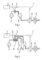
- Schema eines Gasturbinenprozesses mit Dampfeinblasung und einstufiger Turbine,
- Fig. 2
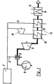
- Schema eines Gasturbinenprozesses mit Hochdruckturbine, Niederdruckturbine und Zwischenerhitzung sowie Dampfeinblasung,
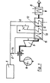
- Fig. 3
- Schema eines Gasturbinenprozesses mit Dampfeinblasung entsprechend Fig. 1 bei dem zusätzlich eine Dampfturbine integriert ist und
- Fig. 4
- Schema eines Gasturbinenprozesses mit Dampfeinblasung und integrierter Dampfturbine nach Fig. 3, bei dem der Dampf hinter der Dampfturbine einem Zwischenüberhitzer zugeführt wird.
- Figur 1-4 zeigen, soweit im einzelnen dargestellt, eine Gasturbine mit einem Luftverdichter 4 und einer Turbine 5, wobei die Turbine 5 über eine Brennkammer 3 in Strömungsverbindung mit dem Luftverdichter 4 steht, denselben antreibt und Wellenleistung abgibt. Der Luftverdichter 4 liefert nur die zur Verbrennung des in die Brennkammer 3 eingebrachten Kraftstoffes erforderliche Luftmenge. Die Abkühlung der Brennkammergase erfolgt durch Zugabe von Wasserdampf, der einer externen Dampfquelle 1 bei Brennkammerdruck entnommen und über eine Leitung 2 in die Brennkammer 3 geleitet wird. Dort wird ein homogenes Gemisch aus Brennkammergas und Wasserdampf gebildet, das die zulässige Turbineneintrittstemperatur aufweist.
- Nach Austritt aus der Turbine 5 wird das Abgas in einem Abhitzekessel 6 abgekühlt. Im Abhitzekessel 6 wird Wasser verdampft, das als Wasserdampf über eine Abhitzedampfleitung 7 zur Leitung 2 gelangt und sich dort mit dem Wasserdampf aus der externen Dampfquelle 1 vermischt.
- Nach Verlassen des Abhitzekessels 6 gelangt das Abgas in den Abgaskondensator 8, wo es bis unterhalb der Taupunkttemperatur abgekühlt wird. Die Kühlwärme steht zu Heizzwecken zur Verfügung oder wird in einem Kühlturm an die Umgebung abgeführt. Das anfallende Kondensat wird nach entsprechender Aufbereitung als Speisewasser verwendet. Das Abgas gelangt nach Verlassen des Abgaskondensators in einen Schornstein.
- Die Anordnung von Figur 2 unterscheidet sich von der der Figur 1 durch die Aufteilung der Turbine 5 in eine Hochdruckturbine 9 und eine Niederdruckturbine 10. Nach der Teilentspannung des Abgases in der Hochdruckturbine 9 wird dieses in einem Wärmetauscher 11 zwischenerhitzt und anschließend in der Niederdruckturbine 10 entspannt. Der Wärmetauscher 11, der im Brennkammergasstrom vor der Hochdruckturbine 9 angeordnet ist, dient gleichzeitig zum Abkühlen der Brennkammergase, so daß bei dieser Anordnung die Brennkammergase sowohl durch Mischen mit Wasserdampf als auch durch Wärmeübertragung gekühlt werden.
- Bei der Dampfquelle 1 kann es sich in beiden Anordnungen um ein beliebiges Dampfkraftwerk oder um eine Dampfprozeßanlage handeln, wobei die gesamte Niederdruckdampfmenge durch die entsprechend dimensionierte Gasturbine geleitet wird.
- Im Gegensatz zu bisher verwendeten Formen der Dampfeinblasung in Gasturbinenbrennkammern, etwa zur NOx-Reduzierung, wird bei der Erfindung davon ausgegangen, daß die gesamte Dampfmenge eines Dampfkraftwerkes oder zumindest ein wesentlicher Anteil davon nicht mehr im Niederdruckteil der Dampfturbine sondern in der nachgeschalteten Gasturbine entspannt wird. Der hier beschriebene Prozeß kann also gleichzeitig zur Leistungserhöhung der Gasturbine und des Dampfprozesses verwendet werden. Die Erfindung ist daher auch zur Nachrüstung vorhandener Dampfkraftwerke geeignet.
- Fig. 3 stellt eine vorteilhafte Weiterbildung der Erfindung gemäß den Grundschaltungen nach den Fig. 1 und 2 dar und kann bei beiden Grundschaltungen verwendet werden. Dazu wird der Abhitzekessel 6 in einen Zweidruckkessel 12 integriert. Der Hochdruckteil 13 des Zweidruckkessels 12 versorgt eine Gegendruckturbine 14 mit Hochdruckdampf, der dort mit weiterer Leistungsabgabe auf den Brennkammerdruck der Brennkammer 3 entspannt wird. Die Heizflächen des Hochdruckteils 13 und des Niederdruckteils( Abhitzekessel 6 ) sind dabei so angeordnet, daß die Temperaturdifferenzen zwischen Rauchgas- und Dampfseite möglichst gering sind. Die sich dann ergebende Verkämmung der Heizflächen von Hochdruck- 13 und Niederdruckteil( Abhitzekessel 6 ) im Zweidruckkessel 12 ist in Fig. 3 wegen der besseren Übersichtlichkeit weggelassen worden.
- Eine andere vorteilhafte Weiterbildung der Erfindung, wieder für beide Grundschaltungen nach den Fig. 1 und 2 geeignet, zeigt Fig. 4. Der Grundgedanke hierbei ist, daß der mit relativ niedriger Temperatur vorliegende Niederdruckdampf in den Abhitzekessel (Zweidruckkessel 12) zurückgeführt und dort in einem Zwischenüberhitzer 15 soweit wie möglich überhitzt wird, bevor er zu der Brennkammer geleitet wird. Die Zwischenüberhitzung reduziert bei gleichem Rauchgasabwärmestrom die Dampferzeugung im Abhitzekessel und beeinflußt damit die Leistung der Gasturbine. Deshalb kann es sinnvoll sein, nur einen oder zwei der drei verfügbaren Niederdruckdampfströme ( von der externer Dampfquelle 1, vom Niederdruckteil( Abhitzekessel 6 ) oder von der Gegndruckturbine 14) zum Zwischenüberhitzer 15 zu führen und den oder die verbleibenden Niederdruckdampfströme ohne Zwischenüberhitzung direkt in die Brennkammer 3 einzudüsen. Zur Vereinfachung ist dies in Fig. 4 durch ein Ventil 16 in der Leitung 2 angedeutet.
- Das erfindungsgemäße Verfahren gestattet, unter Verwendung gängiger Komponenten eine Gasturbine als Teil eines Dampfprozesses zu betreiben, die sich durch hohen thermodynamische Wirkungsgrad, hohe Leistung und niedrige Schadstoffemission auszeichnet.
- Die Zwischenüberhitzung nach der Gegendruckturbine ist auch unabhängig vom Vorhandensein einer externen Dampfquelle im sogenannten Cheng- oder STIG-Prozeß als Prozeßverbesserung einsetzbar.
Claims (6)
- Verfahren zum Betreiben einer Gasturbine als Teil eines Dampfprozesses, wobei die Gasturbine zumindest einen Luftverdichter (4), eine Brennkammer (3) und eine Turbine (5, 10) aufweist, die den Luftverdichter (4) antreibt und Wellenleistung abgibt, wobei der Luftverdichter (4) zumindest das zur Verbrennung erforderliche Luftvolumen fördert, wobei die Abkühlung des Brennkammergases auf die zulässige Turbineneintrittstemperatur zumindest teilweise durch Vermischen desselben mit Wasserdampf erfolgt, der einer Dampfquelle (1), die als Dampfkraftanlage, Dampfprozeßanlage oder Dampfheizanlage ausgebildet ist, bei mindestens Brennkammerdruck entnommen wird, und wobei die Abgaswärme hinter der Turbine (5, 10) zur Erzeugung von Wasserdampf in einem Abhitzekessel (6) genutzt wird, der in einer Dampfturbine (14) entspannbar ist,
dadurch gekennzeichnet, daß zumindest ein Teil des die Dampfturbine (14) verlassenden Dampfes oder aus der Dampfquelle (1) oder aus dem Abhitzekessel (6) kommenden Dampfes in einem Zwischenüberhitzer (15) von der Abgaswärme hinter der Turbine (5, 10) erwärmt und zum Mischen mit den Brennkammergasen verwendet wird. - Verfahren nach Anspruch 1,
dadurch gekennzeichnet, daß die Abgaswärme hinter der Turbine (5, 10) zur Erzeugung von Wasserdampf in einem Zweidruckkessel (12) genutzt wird, wobei der Dampf aus dem Hochdruckteil (13) des Zweidruckkessels (12) der Dampfturbine (14) zugeführt wird. - Verfahren nach einem der Ansprüche 1 oder 2,
dadurch gekennzeichnet, daß der Abgasstrom bis unter den Taupunkt abgekühlt und die dazu erforderliche Kühlwärme vorzugsweise zum Heizen dient. - Verfahren nach einem der vorhergehenden Ansprüche,
dadurch gekennzeichnet, daß die Gasturbine mit Zwischenerhitzung zwischen einer Hochdruckturbine (9) und einer Niederdruckturbine (10) arbeitet, wobei das Abgas der Hochdruckturbine (9) durch Wärmeübertragung vom Brennkammergas vor der Hochdruckturbine (9) aufgeheizt wird. - Verfahren nach einem der vorhergehenden Ansprüche,
dadurch gekennzeichnet, daß das Brennkammergas vor Eintritt in die Turbine (5) durch Wärmeübertragung auf Wasser und Wasserdampf gekühlt wird, wobei der Wasserdampf in einem getrennten Dampfprozeß verwendet wird. - Verfahren nach einem der vorhergehenden Ansprüche,
dadurch gekennzeichnet, daß die Leitschaufeln zumindest der ersten Stufe der Turbine (5, 9, 10) mit Wasserdampf beschickt werden, der nach dem Kühlen der Schaufeln in das Brennkammergas gelangt.
Applications Claiming Priority (3)
| Application Number | Priority Date | Filing Date | Title |
|---|---|---|---|
| DE4223528 | 1992-07-17 | ||
| DE4223528A DE4223528A1 (de) | 1992-07-17 | 1992-07-17 | Verfahren zum Betreiben einer Gasturbine |
| PCT/EP1993/001842 WO1994002728A1 (de) | 1992-07-17 | 1993-07-14 | Verfahren zum betreiben einer gasturbine |
Publications (2)
| Publication Number | Publication Date |
|---|---|
| EP0650554A1 EP0650554A1 (de) | 1995-05-03 |
| EP0650554B1 true EP0650554B1 (de) | 1996-12-18 |
Family
ID=6463430
Family Applications (1)
| Application Number | Title | Priority Date | Filing Date |
|---|---|---|---|
| EP93915904A Expired - Lifetime EP0650554B1 (de) | 1992-07-17 | 1993-07-14 | Verfahren zum betreiben einer gasturbine |
Country Status (8)
| Country | Link |
|---|---|
| EP (1) | EP0650554B1 (de) |
| AT (1) | ATE146563T1 (de) |
| DE (2) | DE4223528A1 (de) |
| DK (1) | DK0650554T3 (de) |
| ES (1) | ES2096308T3 (de) |
| GR (1) | GR3022782T3 (de) |
| RU (1) | RU95105594A (de) |
| WO (1) | WO1994002728A1 (de) |
Families Citing this family (10)
| Publication number | Priority date | Publication date | Assignee | Title |
|---|---|---|---|---|
| CA2131042A1 (en) * | 1993-09-29 | 1995-03-30 | Mark A. Stiehl | Holder for cartridge-needle unit |
| DE19535228C2 (de) * | 1995-09-22 | 2003-05-08 | Alstom | Verfahren zum Betrieb einer Kraftwerksanlage |
| RU2138660C1 (ru) * | 1996-03-14 | 1999-09-27 | Перельштейн Борис Хаимович | Способ работы газотурбинной установки |
| DE19756329A1 (de) * | 1997-12-18 | 1999-06-24 | Gas Elektrizitaets Und Wasserw | Kraftwerksanlage |
| RU2138662C1 (ru) * | 1998-03-31 | 1999-09-27 | Федеральное государственное унитарное предприятие Конструкторское бюро химавтоматики | Способ получения нейтрального газа с помощью газовой турбины и устройство для его осуществления |
| DE19918347A1 (de) * | 1999-04-22 | 2000-10-26 | Asea Brown Boveri | Verfahren und Vorrichtung zur schnellen Leistungssteigerung und Sicherstellung einer Zusatzleistung einer Gasturbinenanlage |
| RU2178827C2 (ru) * | 2000-02-16 | 2002-01-27 | ЗАО "Научно-технический центр ГПА" | Способ утилизации низкопотенциальной энергии выхлопных газов газотурбинной установки и установка утилизации низкопотенциальной энергии выхлопных газов газотурбинной установки для осуществления способа |
| RU2315881C1 (ru) * | 2006-06-15 | 2008-01-27 | Николай Борисович Болотин | Силовая установка локомотива с замкнутой схемой охлаждения турбины |
| DE102011109948A1 (de) * | 2011-08-10 | 2013-02-14 | h s beratung GmbH & Co. KG | Gasturbine |
| RU2545261C9 (ru) * | 2013-03-04 | 2015-06-10 | Александр Алексеевич Белоглазов | Газотурбинная установка повышенной эффективности |
Family Cites Families (11)
| Publication number | Priority date | Publication date | Assignee | Title |
|---|---|---|---|---|
| DE767491C (de) * | 1935-12-09 | 1952-09-08 | Anxionnaz Rene | Waermekraftanlage mit Gasturbinen mit Gleichdruckverbrennung |
| GB575895A (en) * | 1944-08-30 | 1946-03-11 | Michael Steinschlaeger | A power plant |
| US3238719A (en) * | 1963-03-19 | 1966-03-08 | Eric W Harslem | Liquid cooled gas turbine engine |
| US3446482A (en) * | 1967-03-24 | 1969-05-27 | Gen Electric | Liquid cooled turbine rotor |
| FR2092741B1 (de) * | 1970-06-15 | 1973-01-12 | Gendrot Michel | |
| DE2743550A1 (de) * | 1977-09-28 | 1979-04-05 | Mitsui Shipbuilding Eng | Vorrichtung zur beschickung einer turbine mit einem in einem hochofen erzeugten abgas |
| US4314442A (en) * | 1978-10-26 | 1982-02-09 | Rice Ivan G | Steam-cooled blading with steam thermal barrier for reheat gas turbine combined with steam turbine |
| SU883537A1 (ru) * | 1979-07-27 | 1981-11-23 | Ленинградский Ордена Ленина Политехнический Институт Им. М.И.Калинина | Теплофикационна газотурбинна установка |
| US4631914A (en) * | 1985-02-25 | 1986-12-30 | General Electric Company | Gas turbine engine of improved thermal efficiency |
| DE3815993A1 (de) * | 1988-05-10 | 1989-11-23 | Rudolf Dr Wieser | Zweistoff-turbinenanlage |
| IT1243682B (it) * | 1989-07-28 | 1994-06-21 | Gen Electric | Raffreddamento a vapore di turbomotore a gas |
-
1992
- 1992-07-17 DE DE4223528A patent/DE4223528A1/de not_active Withdrawn
-
1993
- 1993-07-14 EP EP93915904A patent/EP0650554B1/de not_active Expired - Lifetime
- 1993-07-14 WO PCT/EP1993/001842 patent/WO1994002728A1/de not_active Ceased
- 1993-07-14 ES ES93915904T patent/ES2096308T3/es not_active Expired - Lifetime
- 1993-07-14 DE DE59304831T patent/DE59304831D1/de not_active Expired - Fee Related
- 1993-07-14 AT AT93915904T patent/ATE146563T1/de not_active IP Right Cessation
- 1993-07-14 RU RU95105594/06A patent/RU95105594A/ru unknown
- 1993-07-14 DK DK93915904.2T patent/DK0650554T3/da active
-
1997
- 1997-03-11 GR GR970400466T patent/GR3022782T3/el unknown
Also Published As
| Publication number | Publication date |
|---|---|
| GR3022782T3 (en) | 1997-06-30 |
| DK0650554T3 (da) | 1997-03-17 |
| WO1994002728A1 (de) | 1994-02-03 |
| DE4223528A1 (de) | 1994-01-20 |
| ATE146563T1 (de) | 1997-01-15 |
| DE59304831D1 (de) | 1997-01-30 |
| RU95105594A (ru) | 1996-11-20 |
| ES2096308T3 (es) | 1997-03-01 |
| EP0650554A1 (de) | 1995-05-03 |
Similar Documents
| Publication | Publication Date | Title |
|---|---|---|
| DE69201312T2 (de) | Erdgasturbine mit Wasserdampfeinspritzung im halboffenen Kreislauf. | |
| EP0150340B1 (de) | Verfahren zum Betreiben einer kombinierten Gas-Dampfturbinen-Kraftwerkanlage | |
| DE69429769T2 (de) | Mehrwellen, zwischenheizungsgasturbine mit zwischenkühlung und wärmerückgewinnung | |
| EP0597305B2 (de) | Verfahren zum Betrieb einer Kombianlage | |
| DE69517623T2 (de) | Dampfeinspritzgasturbinensystem mit Hochdruckdampfturbine | |
| EP0591163B1 (de) | Kombinierte gas- und dampfturbinenanlage | |
| DE68907191T2 (de) | Verfahren und vorrichtung zum optimieren der temperatur der von einer gasturbine angesaugten luft. | |
| DE60033357T2 (de) | Kombikraftwerk mit Gasturbine | |
| DE102004039164A1 (de) | Verfahren zur Erzeugung von Energie in einer eine Gasturbine umfassenden Energieerzeugungsanlage sowie Energieerzeugungsanlage zur Durchführung des Verfahrens | |
| DE10001997A1 (de) | Verbund-Kraftwerk sowie Verfahren zum Betrieb eines solchen Verbund-Kraftwerkes | |
| EP0558899A1 (de) | Anordnung zur Nutzung der im Abgas eines kohlegefeuerten Kessels enthaltenen Wärme | |
| EP0424660A1 (de) | Gas/Dampf-Kraftwerksanlage | |
| WO1999019608A1 (de) | Gas- und dampfturbinenanlage und verfahren zum betreiben einer derartigen anlage | |
| WO2000020728A1 (de) | Gas- und dampfturbinenanlage | |
| EP0650554B1 (de) | Verfahren zum betreiben einer gasturbine | |
| EP0584072B1 (de) | Gas- und dampfturbinenanlage | |
| WO2000011325A1 (de) | Gas- und dampfturbinenanlage | |
| WO2000004279A2 (de) | Gas- und dampfturbinenanlage | |
| DE3419560A1 (de) | Verfahren zum betrieb einer gasturbinenanlage sowie anlage zur durchfuehrung des verfahrens | |
| DE3331153A1 (de) | Gasturbinenanlage fuer offenen prozess | |
| DE4441324C1 (de) | Anordnung zur Nutzung der im Rauchgas eines kohlegefeuerten Dampferzeugers enthaltenen Wärme | |
| DE3815993A1 (de) | Zweistoff-turbinenanlage | |
| DE4025527C1 (en) | Steam boiler with economiser - incorporates combustion chamber with recirculation circuit | |
| DE4409811C1 (de) | Verfahren zum Betreiben eines Abhitzedampferzeugers sowie danach arbeitender Abhitzedampferzeuger | |
| EP0424864B1 (de) | Kraftwerksanlage |
Legal Events
| Date | Code | Title | Description |
|---|---|---|---|
| PUAI | Public reference made under article 153(3) epc to a published international application that has entered the european phase |
Free format text: ORIGINAL CODE: 0009012 |
|
| 17P | Request for examination filed |
Effective date: 19941205 |
|
| AK | Designated contracting states |
Kind code of ref document: A1 Designated state(s): AT BE CH DE DK ES FR GB GR IE IT LI NL PT SE |
|
| 17Q | First examination report despatched |
Effective date: 19950613 |
|
| GRAG | Despatch of communication of intention to grant |
Free format text: ORIGINAL CODE: EPIDOS AGRA |
|
| GRAH | Despatch of communication of intention to grant a patent |
Free format text: ORIGINAL CODE: EPIDOS IGRA |
|
| GRAH | Despatch of communication of intention to grant a patent |
Free format text: ORIGINAL CODE: EPIDOS IGRA |
|
| GRAA | (expected) grant |
Free format text: ORIGINAL CODE: 0009210 |
|
| AK | Designated contracting states |
Kind code of ref document: B1 Designated state(s): AT BE CH DE DK ES FR GB GR IE IT LI NL PT SE |
|
| REF | Corresponds to: |
Ref document number: 146563 Country of ref document: AT Date of ref document: 19970115 Kind code of ref document: T |
|
| REF | Corresponds to: |
Ref document number: 59304831 Country of ref document: DE Date of ref document: 19970130 |
|
| REG | Reference to a national code |
Ref country code: IE Ref legal event code: FG4D Free format text: 71126 |
|
| REG | Reference to a national code |
Ref country code: CH Ref legal event code: NV Representative=s name: R. A. EGLI & CO. PATENTANWAELTE |
|
| GBT | Gb: translation of ep patent filed (gb section 77(6)(a)/1977) |
Effective date: 19970125 |
|
| ITF | It: translation for a ep patent filed | ||
| REG | Reference to a national code |
Ref country code: ES Ref legal event code: FG2A Ref document number: 2096308 Country of ref document: ES Kind code of ref document: T3 |
|
| ET | Fr: translation filed | ||
| REG | Reference to a national code |
Ref country code: DK Ref legal event code: T3 |
|
| ET | Fr: translation filed |
Free format text: CORRECTIONS |
|
| REG | Reference to a national code |
Ref country code: GR Ref legal event code: FG4A Free format text: 3022782 |
|
| PLBE | No opposition filed within time limit |
Free format text: ORIGINAL CODE: 0009261 |
|
| STAA | Information on the status of an ep patent application or granted ep patent |
Free format text: STATUS: NO OPPOSITION FILED WITHIN TIME LIMIT |
|
| 26N | No opposition filed | ||
| PGFP | Annual fee paid to national office [announced via postgrant information from national office to epo] |
Ref country code: GR Payment date: 19990630 Year of fee payment: 7 |
|
| PGFP | Annual fee paid to national office [announced via postgrant information from national office to epo] |
Ref country code: BE Payment date: 19990705 Year of fee payment: 7 Ref country code: SE Payment date: 19990705 Year of fee payment: 7 Ref country code: PT Payment date: 19990705 Year of fee payment: 7 Ref country code: IE Payment date: 19990705 Year of fee payment: 7 |
|
| PGFP | Annual fee paid to national office [announced via postgrant information from national office to epo] |
Ref country code: AT Payment date: 19990707 Year of fee payment: 7 |
|
| PGFP | Annual fee paid to national office [announced via postgrant information from national office to epo] |
Ref country code: GB Payment date: 19990708 Year of fee payment: 7 |
|
| PGFP | Annual fee paid to national office [announced via postgrant information from national office to epo] |
Ref country code: DK Payment date: 19990716 Year of fee payment: 7 |
|
| PGFP | Annual fee paid to national office [announced via postgrant information from national office to epo] |
Ref country code: ES Payment date: 19990729 Year of fee payment: 7 |
|
| PGFP | Annual fee paid to national office [announced via postgrant information from national office to epo] |
Ref country code: NL Payment date: 19990730 Year of fee payment: 7 Ref country code: FR Payment date: 19990730 Year of fee payment: 7 |
|
| PGFP | Annual fee paid to national office [announced via postgrant information from national office to epo] |
Ref country code: DE Payment date: 19990803 Year of fee payment: 7 |
|
| PGFP | Annual fee paid to national office [announced via postgrant information from national office to epo] |
Ref country code: CH Payment date: 19991029 Year of fee payment: 7 |
|
| PG25 | Lapsed in a contracting state [announced via postgrant information from national office to epo] |
Ref country code: IE Free format text: LAPSE BECAUSE OF NON-PAYMENT OF DUE FEES Effective date: 20000714 Ref country code: GB Free format text: LAPSE BECAUSE OF NON-PAYMENT OF DUE FEES Effective date: 20000714 Ref country code: DK Free format text: LAPSE BECAUSE OF NON-PAYMENT OF DUE FEES Effective date: 20000714 Ref country code: AT Free format text: LAPSE BECAUSE OF NON-PAYMENT OF DUE FEES Effective date: 20000714 |
|
| PG25 | Lapsed in a contracting state [announced via postgrant information from national office to epo] |
Ref country code: SE Free format text: LAPSE BECAUSE OF NON-PAYMENT OF DUE FEES Effective date: 20000715 Ref country code: ES Free format text: LAPSE BECAUSE OF NON-PAYMENT OF DUE FEES Effective date: 20000715 |
|
| PG25 | Lapsed in a contracting state [announced via postgrant information from national office to epo] |
Ref country code: LI Free format text: LAPSE BECAUSE OF NON-PAYMENT OF DUE FEES Effective date: 20000731 Ref country code: GR Free format text: LAPSE BECAUSE OF NON-PAYMENT OF DUE FEES Effective date: 20000731 Ref country code: CH Free format text: LAPSE BECAUSE OF NON-PAYMENT OF DUE FEES Effective date: 20000731 Ref country code: BE Free format text: LAPSE BECAUSE OF NON-PAYMENT OF DUE FEES Effective date: 20000731 |
|
| BERE | Be: lapsed |
Owner name: GAS- ELEKTRIZITATS- UND WASSERWERKE KOLN A.G. Effective date: 20000731 |
|
| PG25 | Lapsed in a contracting state [announced via postgrant information from national office to epo] |
Ref country code: PT Free format text: LAPSE BECAUSE OF NON-PAYMENT OF DUE FEES Effective date: 20010131 |
|
| PG25 | Lapsed in a contracting state [announced via postgrant information from national office to epo] |
Ref country code: NL Free format text: LAPSE BECAUSE OF NON-PAYMENT OF DUE FEES Effective date: 20010201 |
|
| GBPC | Gb: european patent ceased through non-payment of renewal fee |
Effective date: 20000714 |
|
| REG | Reference to a national code |
Ref country code: CH Ref legal event code: PL |
|
| EUG | Se: european patent has lapsed |
Ref document number: 93915904.2 |
|
| REG | Reference to a national code |
Ref country code: DK Ref legal event code: EBP |
|
| PG25 | Lapsed in a contracting state [announced via postgrant information from national office to epo] |
Ref country code: FR Free format text: LAPSE BECAUSE OF NON-PAYMENT OF DUE FEES Effective date: 20010330 |
|
| NLV4 | Nl: lapsed or anulled due to non-payment of the annual fee |
Effective date: 20010201 |
|
| REG | Reference to a national code |
Ref country code: FR Ref legal event code: ST |
|
| PG25 | Lapsed in a contracting state [announced via postgrant information from national office to epo] |
Ref country code: DE Free format text: LAPSE BECAUSE OF NON-PAYMENT OF DUE FEES Effective date: 20010501 |
|
| REG | Reference to a national code |
Ref country code: IE Ref legal event code: MM4A |
|
| REG | Reference to a national code |
Ref country code: PT Ref legal event code: MM4A Free format text: LAPSE DUE TO NON-PAYMENT OF FEES Effective date: 20010131 |
|
| REG | Reference to a national code |
Ref country code: ES Ref legal event code: FD2A Effective date: 20010810 |
|
| PG25 | Lapsed in a contracting state [announced via postgrant information from national office to epo] |
Ref country code: IT Free format text: LAPSE BECAUSE OF NON-PAYMENT OF DUE FEES;WARNING: LAPSES OF ITALIAN PATENTS WITH EFFECTIVE DATE BEFORE 2007 MAY HAVE OCCURRED AT ANY TIME BEFORE 2007. THE CORRECT EFFECTIVE DATE MAY BE DIFFERENT FROM THE ONE RECORDED. Effective date: 20050714 |