EP0649709A2 - Gerät zur Bewegung eines mobilen Roboters - Google Patents
Gerät zur Bewegung eines mobilen Roboters Download PDFInfo
- Publication number
- EP0649709A2 EP0649709A2 EP94307828A EP94307828A EP0649709A2 EP 0649709 A2 EP0649709 A2 EP 0649709A2 EP 94307828 A EP94307828 A EP 94307828A EP 94307828 A EP94307828 A EP 94307828A EP 0649709 A2 EP0649709 A2 EP 0649709A2
- Authority
- EP
- European Patent Office
- Prior art keywords
- hypothesis
- data
- sonar
- interpretation
- stereo
- Prior art date
- Legal status (The legal status is an assumption and is not a legal conclusion. Google has not performed a legal analysis and makes no representation as to the accuracy of the status listed.)
- Withdrawn
Links
- 230000008094 contradictory effect Effects 0.000 claims description 6
- 238000012795 verification Methods 0.000 description 47
- 238000001514 detection method Methods 0.000 description 20
- 238000000034 method Methods 0.000 description 15
- 230000004438 eyesight Effects 0.000 description 8
- 230000010354 integration Effects 0.000 description 8
- 230000015572 biosynthetic process Effects 0.000 description 5
- 238000005070 sampling Methods 0.000 description 5
- 238000012545 processing Methods 0.000 description 3
- 238000010586 diagram Methods 0.000 description 2
- 239000011521 glass Substances 0.000 description 2
- 238000005259 measurement Methods 0.000 description 2
- 238000011160 research Methods 0.000 description 2
- 230000001154 acute effect Effects 0.000 description 1
- 230000005540 biological transmission Effects 0.000 description 1
- 239000012141 concentrate Substances 0.000 description 1
- 238000007796 conventional method Methods 0.000 description 1
- 230000004069 differentiation Effects 0.000 description 1
- 238000006073 displacement reaction Methods 0.000 description 1
- 230000002349 favourable effect Effects 0.000 description 1
- 238000010304 firing Methods 0.000 description 1
- 230000004927 fusion Effects 0.000 description 1
- 238000004519 manufacturing process Methods 0.000 description 1
- 238000013507 mapping Methods 0.000 description 1
- 230000003287 optical effect Effects 0.000 description 1
- 230000005855 radiation Effects 0.000 description 1
- 230000035945 sensitivity Effects 0.000 description 1
- 238000007619 statistical method Methods 0.000 description 1
- 230000003746 surface roughness Effects 0.000 description 1
- 238000003786 synthesis reaction Methods 0.000 description 1
- 230000002194 synthesizing effect Effects 0.000 description 1
- 230000000007 visual effect Effects 0.000 description 1
Images


Classifications
-
- G—PHYSICS
- G05—CONTROLLING; REGULATING
- G05D—SYSTEMS FOR CONTROLLING OR REGULATING NON-ELECTRIC VARIABLES
- G05D1/00—Control of position, course or altitude of land, water, air, or space vehicles, e.g. automatic pilot
- G05D1/02—Control of position or course in two dimensions
- G05D1/021—Control of position or course in two dimensions specially adapted to land vehicles
- G05D1/0255—Control of position or course in two dimensions specially adapted to land vehicles using acoustic signals, e.g. ultra-sonic singals
-
- G—PHYSICS
- G05—CONTROLLING; REGULATING
- G05D—SYSTEMS FOR CONTROLLING OR REGULATING NON-ELECTRIC VARIABLES
- G05D1/00—Control of position, course or altitude of land, water, air, or space vehicles, e.g. automatic pilot
- G05D1/02—Control of position or course in two dimensions
- G05D1/021—Control of position or course in two dimensions specially adapted to land vehicles
- G05D1/0231—Control of position or course in two dimensions specially adapted to land vehicles using optical position detecting means
- G05D1/0246—Control of position or course in two dimensions specially adapted to land vehicles using optical position detecting means using a video camera in combination with image processing means
- G05D1/0251—Control of position or course in two dimensions specially adapted to land vehicles using optical position detecting means using a video camera in combination with image processing means extracting 3D information from a plurality of images taken from different locations, e.g. stereo vision
-
- H—ELECTRICITY
- H04—ELECTRIC COMMUNICATION TECHNIQUE
- H04N—PICTORIAL COMMUNICATION, e.g. TELEVISION
- H04N13/00—Stereoscopic video systems; Multi-view video systems; Details thereof
- H04N13/10—Processing, recording or transmission of stereoscopic or multi-view image signals
-
- H—ELECTRICITY
- H04—ELECTRIC COMMUNICATION TECHNIQUE
- H04N—PICTORIAL COMMUNICATION, e.g. TELEVISION
- H04N13/00—Stereoscopic video systems; Multi-view video systems; Details thereof
- H04N13/20—Image signal generators
- H04N13/204—Image signal generators using stereoscopic image cameras
- H04N13/239—Image signal generators using stereoscopic image cameras using two 2D image sensors having a relative position equal to or related to the interocular distance
-
- H—ELECTRICITY
- H04—ELECTRIC COMMUNICATION TECHNIQUE
- H04N—PICTORIAL COMMUNICATION, e.g. TELEVISION
- H04N13/00—Stereoscopic video systems; Multi-view video systems; Details thereof
- H04N2013/0074—Stereoscopic image analysis
- H04N2013/0081—Depth or disparity estimation from stereoscopic image signals
Definitions
- the present invention relates to a device for moving a robot and, more particularly, to a device for moving a robot based on the surrounding environment.
- Mobile robots are used in manufacturing plants to transport loads. Many such mobile robots either move along a given run guide such as a rail or provide a detector (herein referred to as an inside angle sensor) for detecting the run distance in accordance with a route stored in the mobile robot in advance to enable it to move based on detected values.
- Some mobile robots have detectors such as ultrasonic wave sensors to avoid obstacles present in the direction of movement of the mobile robot or to detect the status of surroundings by using a bumper (fender) to detect the obstacle based on data (herein referred to as sensor data) on detected values used to avoid obstacles.
- the configuration of a scene referred to herein means an environment established in the structure, including artificial objects and natural objects that can be detected by independent mobile robots.
- ultrasonic wave sensors cannot provide accurate information with respect to a surface which is angled relative to the radiative direction of the ultrasonic wave or at an angle involving a curved surface.
- the stereo cameras can obtain distance information on such a surface configuration. Distance information differs with the type of sensor.
- This method provides highly reliable sensor data from an object located outside the dynamic range of sensors or a position that cannot be initially detected by presuming a position favorable for detection and moving a sensor to a different position which is presumed more easily detected by sensors.
- this method requires a movement plan which enables a sensor to be moved to a position for optimal object detection. It is difficult to devise an effective movement plan from sensor data having low reliability, particularly at initial detection. Consequently, for example, a movement plan for detection prevents the original movement and running of independent mobile robots.
- This method suggests a detection structure in which detection intentions are clearly described in given prior information and in an environment setting and in limited knowledge as to what object is measured with what method, and how given information is employed. This method is limited to the conceptual level, however, and no concrete way for realizing is disclosed.
- the present invention provides a device for controlling a mobile robot consisting of: a plurality of sensors of different kinds including at least a sensor which detects the presence of an object and at least a sensor which detects image information related to said object; an interpretation means for interpreting, for each of said sensors, elements of said object based on respective sensor data obtained from said plurality of sensors; a hypothesis generation means to generate a hypothesis expressing a configuration of said object based on said elements of said object interpreted for each of said sensors by referencing a table in which interpretations of said respective sensors with respect to predetermined configurations of objects are stored in advance; and a movement means for moving a mobile robot by using the generated hypothesis.
- an embodiment of the present invention comprises a plurality of sensors
- an embodiment can equally well be realised which does not comprise such a plurality of sensors providing means for receiving data from such sensors is provided.
- a further embodiment of the present invention provides a device for moving a mobile robot comprising a plurality of different sensors including a sensor which detects the presence of an object and a sensor which detects image information related to the object; an interpretation means for interpreting, for each of said sensors, an element of said object; a hypothesis generation means for referencing a table in which interpretations of said respective sensors with respect to predetermined configurations of objects are stored in advance, and for generating a hypothesis expressing a configuration of said objects based on the elements of said object interpreted for each of said sensors, verifying a hypothesis generated based on sensor data obtained with the passage of time, and using said verified hypothesis when said hypothesis is correct and discarding said hypothesis when said hypothesis is contradictory; and a movement means for moving a mobile robot by using said hypothesis.
- the above hypothesis generation means references a table in which all combinations of interpretations that should be generated are stored for each of said sensors with respect to each of the classified surface configurations of objects determined in advance.
- Independent mobile robots require environment recognition based on detected sensor values for safe operation. If one type of sensor is used, recognizable objects and distances are limited, so reliability and the recognizable scope are insufficient.
- an embodiment of the present invention proposes a technique for integrating sensor data obtained from a plurality of different sensors, the data being effective in the environment interpretation for the movement and running of independent mobile robots that operate while avoiding obstacles.
- the different sensors comprise, for example, an ultrasonic sensor that obtains distance information as sensor data and stereo cameras that obtains sensor data as three-dimensional information.
- the sonar is effective in detecting a large surface and can detect a surface element that is an element of an object.
- the stereo cameras can detect image information related to the object by obtaining three-dimensional information generated by the edge of gray scale variation in images.
- Mobile robots are guided by a hypothesis expressing the configuration of an object from sensor data obtained from different sensors.
- interpretations for each sensor with respect to the configuration of the preliminarily determined object are defined in a table where data from sonar or stereo cameras with the surface configuration of a scene that constitutes an object is assigned a priority.
- the table is stored in the hypothesis generation means.
- the hypothesis generation means refers to this table and generates a hypothesis expressing the configuration of the object by means such as using an interpretation obtained from each of the sensors and free from geometrical contradictions based on an element of the object interpreted for each of the sensors. Since this generated hypothesis can be regarded as a map of the surrounding environment, the generated hypothesis can be used for guiding a mobile robot with the movement means.
- Sonar may interpret some surface configuration as a surface with an incorrect configuration depending on the surface configuration.
- the stereo cameras can also obtain three-dimensional information including the surface from the edge of a continuous-tone portion in images. In some cases, it is difficult to reconstitute the surface from this three-dimensional information.
- the hypothesis generation means generates, from an interpretation for each of the sensors, a hypothesis expressing the configuration of an object based on an element of the object, uses an interpretation generated based on sensor data obtained with the passage of time thereafter, and verifies the hypothesis by referring to a table in which the result of the verification is stored in advance with respect to the configuration of the preliminarily defined object and an interpretation for each of the sensors.
- the generated hypothesis is used as is. If the hypothesis is contradictory, the generated hypothesis is discarded and a new hypothesis is generated. Verification of this generated hypothesis is repeated by using an interpretation for each of the sensors.
- a hypothesis is generated by using an interpretation free of geometrical contradictions from interpretations obtained from each of the sensors.
- a determination is made preliminarily in a table as to which data is to be assigned priority, data from sonar or from stereo cameras from the object configuration such as the surface configuration of a scene that constitutes this object.
- a hypothesis that can be regarded as an environment map is used to verify the hypothesis by referring to sensor data that can be presumed to be actual sensor data with respect to the surface configuration of the hypothesis. Consequently, it is difficult to reconstitute the surrounding environment from sensor data. It is easy to presume sensor data obtained at this time from a hypothesis such as an environment map expressing the surrounding environment. Consequently, mobile robots are moved by regarding the generated hypothesis as a surrounding environment map.
- the hypothesis is verified by using sensor data obtained with the passage of time during movement. If contradictions are found, the hypothesis is discarded and another interpretation is adopted for use as a new hypothesis.
- the surface configuration is obtained from stereo cameras and the existence of the surface is obtained from sonar sensor data, which makes it possible to compensate for the shortcomings of each of the different types of sensor.
- the previously generated hypothesis can be verified with sensor data obtained with the passage of time. Otherwise, the hypothesis can be verified by generating a hypothesis each time sensor data is obtained.
- an embodiment integrates ambiguous data from multiple sensors. Hypothesis verification can be repeated and the certainty of the environment interpretation improved. It is very important to recognize whether or not an object surface that becomes an obstacle is present on or around the route where the mobile robot operates. The robot does not strictly recognize the environment, such as what the object is. The robot does not act to recognize the object and real-time sensing can be obtained in robot running and movement.
- the hypothesis generation means can refer to a table in which all combinations of interpretations are stored in advance that should be generated for each of the sensors with respect to each of the classified surface configurations by classifying the configuration of the object defined in advance with the surface configuration.
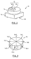
- the mobile robot (10) has different types of sensor that detect different states
- sonar ring device (14) obtains sensor data as distance information to an object by using ultrasonic waves
- stereo cameras (12) obtain sensor data as three-dimensional information by using stereo vision with two cameras (12R) and (12L) (described hereinafter in detail).
- the mobile robot (10) includes a controller (16) consisting of a microcomputer or the like for generating and verifying a hypothesis with respect to the surrounding environment based on signal data from the sonar ring devices (14) and stereo cameras (12) and a run device (18) driven by signals from the controller (16).
- the run device (18) has a distance meter (20) for measuring the run distance of the mobile robot and a direction meter (22) for measuring the direction of the mobile robot ( Figure 1).
- the base line of the stereo cameras (12) is 15 cm long.
- the stereo cameras (12) are disposed so that optical axes (12R and 12L) of the cameras run parallel to each other, and the cameras are inclined at an elevation angle of 18 degrees with respect to the horizontal distance.
- the stereo cameras are disposed so that, for example, a front area of 5 m of the floor is a sight that can be photographed. They enable the obtaining of an image (stereo vision) similar to human vision.
- Cameras (12R and 12L) are connected to the controller (16). Since the sonar ring device (14) detects an object via sound, 8 sonar devices (14A to 14H) having sound senders above directed toward the firing direction and receivers below are equally spaced angularly in a ring configuration ( Figure 3). The sonar ring devices (14) are connected to the controller (16).
- the controller (16) consists of a sonar processor (24), an image processor (26), a hypothesis verification device (36), an environment map (38), run route memory (40), and a run controller (42).
- the hypothesis verification device (36) consists of a sonar interpretation section (28), a stereo interpretation section (30), and a hypothesis formation and verification device (32) having hypothesis memory (34).
- the sonar ring device (14) is connected to the sonar processor (24) to process each of the sonar devices (14A to 14H).
- the sonar processor controls each of the sonar devices (14A to 14H) such that they respectively transmit ultrasonic waves separated by a delay of 25 ms to prevent interference by the ultrasonic wave generated by the other adjacent sonar sensors.
- the transmission frequency is 40 kHz and can measure the distance to an object within a range of 3.0 to 0.1 m.
- the sonar processor (24) is connected to the sonar interpretation section (28).
- each sonar device 14A to 14H
- the directivity of sender-receivers in each sonar devices is not acute, unlike light.
- An ultrasonic beam dissipates and expands in width when transmitted through air.
- the direction along the reflection surface can be measured only to an accuracy of the order of the beam width.
- the surface can be detected on any of the spherical surfaces corresponding to the beam width.
- each sonar device has a detection area whose size is proportional to the distance to an object.
- the detection area where an object around the robot (10) can be detected is given as detection area Vi in the stereo cameras (12), whereas it is given as detection area Sr in the sonar ring device (14).
- the image processor (26) is connected to cameras (12R and 12L) of the stereo cameras (12) to process an image photographed by the cameras (12R and 12L). This processing provides three-dimensional information from each type of image information (video signals or the like) by means of stereo vision formed by cameras (12R and 12L) arranged as shown above.
- This image processor (26) is connected to a stereo interpretation section (30) in the hypothesis verification device (36).
- Three-dimensional information is obtained with this stereo vision at the edge where the brightness of the image changes abruptly.
- the horizontal arrangement of the two cameras enables the obtaining of an image corresponding to an edge which is not planar. However, it is still impossible to obtain an image corresponding to the portion between images at a horizontal edge. Three-dimensional information can then be obtained at a horizontal edge by the correspondence to the end point of the horizontal edge.
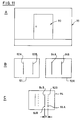
- an image (94) formed by synthesizing processed images (92R and 92L) end points (86A and 86B) should correspond. Spacing between line segments (82B and 848) corresponds to a distance up to the door (80).
- the line segment obtained from line segments (82B and 84B) forms three-dimensional information. The line segment may be described by a position at which the displacement of images is corrected. Otherwise, either line segment (82B or 84B) may be used.
- the hypothesis verification device (36) generates a hypothesis with respect to an environment surrounding the mobile robot (10) from the surface component of an object interpreted at a sonar interpretation section (28) based on sensor data (hereinafter referred to as sonar data) of the sonar ring device (14) and the configuration of the object interpreted at a stereo interpretation section (30) based on sensor data (hereinafter referred to as stereo data) of the stereo cameras (12).
- sonar data sensor data
- stereo data stereo data
- a distance meter (20) and a direction meter (22) are connected to the run controller (42) to specify the current position and direction of the mobile robot (10).
- an environment map device (38) and run route memory (40) are connected to the run controller (42).
- the environment map device (38) stores the surrounding environment map formed by the hypothesis generated at the hypothesis verification device (36). This environment map provides a two-dimensional map as seen when viewed from above.
- Run route memory (40) stores the run route of the mobile robot (10) input in advance by operators or the like.
- the run controller (42) thus controls the run device (18) to move the mobile robot (10) while avoiding an obstacle present on the run route by referring to the running route stored in run route memory (40) and by referring to the environment map obtained from the environment map device (38).
- the movement of the mobile robot (10) according to the embodiment is explained next, together with the movement of the hypothesis verification device (36).
- the sonar interpretation section (28) of hypothesis verification device (36) interprets sonar data
- the stereo interpretation section (30) interprets stereo data.
- the cycle time for detection by the sonar ring device (14) is extremely rapid compared to the speed of mobile robot movement. Since distance information obtained during movement can be obtained densely in a continuous form with the passage of time, information can be integrated as a planar surface component. A determination is made as to whether fine surface elements obtained at continuous sampling points can be connected when the movement of the mobile robot (10) is offset. When the distance in the center of fine surface elements is either equal to the threshold value or less, the distance is integrated as a continuous surface component. At this time, the adjustment of receiver sensitivity may provide noise that is generated independently. If sonar data such as distance data or the like cannot be obtained at a plurality of sampling points that continue with the passage of time, fine surface elements can be eliminated as noise.
- the surface component is described as line segment data, which is registered at the starting and end points.
- the line segment is obtained with the minimum self-multiplication method to register, as a surface component, the intersection point of vertical lines that come down from both ends to the line segment.
- the sonar ring device (14) detects an object by using sound waves as a medium.
- the devices (14) have the following characteristics: Even if an ultrasonic wave may come from any direction to the surface of the object when an uneven 50-angstrom surface (surface roughness) of an object (50) (hereinafter referred to as an object surface) changes irregularly on the order of the wavelength of the ultrasonic wave, part of the scattered wave returns in the direction of sending of the ultrasonic wave, thereby making it possible to obtain distance data.
- an uneven 50-angstrom surface is one digit shorter than the wavelength of the ultrasonic wave, the surface of the object acts as a mirror to reflect the ultrasonic wave.
- the mobile robot can receive a reflected wave from the surface of an object located at right angles or at an angle to the direction of ultrasonic wave radiation by means of one sonar device.
- the robot cannot obtain the reflection wave from a surface having an inclination larger than a particular angle, with the result that data received becomes the same as data in free area (space).
- another sonar device cannot detect the reflection wave. As a result, even when the registered surface component is interpreted to be free area from sonar data from distant sampling points, this interpretation is not to be discarded.
- Stereo data obtained from two cameras is only three-dimensional information along an edge. It is impossible to obtain data from a surface where the brightness changes smoothly on the image ( Figure 11). Consequently, a three-dimensional line segment is assumed connected to the surface, but it is not apparent where the line segment is actually present.
- the edge in the processed image is a place where the direction of the surface (normal line) suddenly changes, i.e. a boundary line whose one surface cannot be seen from the camera, or a mark or shadow drawn on the surface.
- reconstituting the surface from the three-dimensional line segment requires information on which side the surface linked to the three-dimensional line segment is located and other three-dimensional line segment adjacent to another three-dimensional line segment on the image, but the three-dimensional line segment is rough. Although used to reconstitute the surface, a plurality thereof cannot be always obtained at the same time.
- a surface that becomes an obstacle to running of the mobile robot (10) in an indoor environment often stands vertically.
- a vertical surface including three-dimensional line segments is adopted as one interpretation.
- two three-dimensional line segments can be obtained.
- these two three-dimensional line segments are defined as line segments (82A and 82B). Because the vertical surface including these line segments (82A and 82B) overlaps, it can be inferred that one surface occupying space between line segments (82A and 82B) is present.
- this three-dimensional line segment can be interpreted two ways: it can be interpreted so that a surface including this three-dimensional line segment is present, or it can be interpreted so that the line segment is simply drawn on the floor surface.
- this line segment Since many vertical surfaces including this three-dimensional line segment can be considered from a plurality of vertical three-dimensional line segments, the surface located nearest to the mobile robot is interpreted as stereo data. In addition, if the line segment is severed at the boundary of the field of view, or the image frame, it can be inferred that this line segment extends beyond the scope of the field of view.
- hypothesis formation in the hypothesis generation verification portion (32) based on sonar and stereo data is explained next.
- stereo data obtained from the stereo cameras and sonar data such as direction and distance data obtained from the sonar ring devices are dealt with in accordance with the following rules:
- an interpretation nearer to the position of the mobile robot is adopted when the maximum value of the distance made by drawing a vertical line from the shorter line segment to the longer line segment does not exceed the threshold value, or when the distance between the two line segments is not less than the threshold value.
- hypothesis generation surface components are integrated only, and no determination is made about whether or not the hypothesis is contradictory.
- the above processing is equivalent to a method for collecting data nearest to the mobile robot. This embodiment thus provides a way to discard an incorrect interpretation in verification to approximate the hypothesis to an accurate environment map. It is this point that differs sharply from conventional methods in which an incorrect interpretation cannot be discarded.
- the sonar ring devices (14) and the stereo cameras (12) have mutually different areas of detection ( Figure 4).
- the ease of sensor detection differs greatly from one object to another.
- the sonar ring devices (14) cannot interpret surface components without moving and cannot detect distant surfaces.
- the stereo cameras (12) can, in contrast, obtain a three-dimensional edge farther away than the sonar ring devices (14). Since tne direction in which stereo data can be obtained is limited, the reliability of interpretation of the surface from a single three-dimensional edge is very low. Because sensor properties differ, simply interpreting the environment directly from data from each sensor prevents the result of these interpretation from being integrated effectively.
- a large surface component is thus required to integrate data from a plurality of different sensors for use in running a robot.
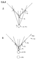
- a determination is made including the region outside the scope of sensor detection, as explained later. For example, as shown in Figure 4, when extensible three-dimensional line segment (52) is interpreted as a surface, and surface component (54) from sonar on line segment 52 is reflected from the surface, the portion from line segment (52) within the stereo cameras (12) range up to surface component (54) is interpreted as a long line segment.
- the determination of whether or not interpretations from different types of sensors are bound or not is made when data in an attribute that can be extended beyond the scope of eyesight in the stereo interpretation and the maximum distance up to a point on the extended line segment or to the line segment is within the scope of the threshold value.
- the robot When the robot moves, it avoids an obstacle by referencing the current environment. If an interpretation of sensor data does not agree with the current hypothesis during movement, the hypothesis is discarded as explained later and the robot is moved optimally with respect to the hypothesis based on a new interpretation.
- the bottom-up method which reconstitutes an environment from sensing data, is ambiguous in interpretation, making it difficult to obtain an accurate environment map.
- the top-down method which involves presuming sensing data from the environment map, is easy to apply because the properties of individual sensor data are already known.
- the hypothesis is regarded as an environment map. Sensing data that can be presumed with respect to the hypothesis is checked against actually detected sensing data, then a determination made on whether or not the hypothesis is to be discarded based on the result presumed in advance. Initially, priority is given to the sensor with respect to the combination of sensor data presumable from the sonar ring devices (14) and the stereo cameras (12) for each surface configuration. A table is prepared in which conclusions are made on whether a hypothesis is to be discarded (Table 1). Surface configuration Ref. No.
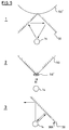
- the sonar ring devices (14) obtain only small surface components in a short time, the surface configuration in the hypothesis uses only the surface component obtained from the stereo cameras (12) and a large surface obtained by binding interpretations in hypothesis generation. Consequently, as opposed to a hypothesis for a uniformly large surface, the four different results of verification shown in Figure 1 can be presumed from the combination of interpretations from the sonar ring devices (14) and stereo data (12). However, in the interpretation of sensor data from the sonar ring devices (14), the verification is made based on the interpretation from the sonar device located vertically with respect to the surface or located within the threshold value. Sonar data having an angle with respect to other surfaces is not used in verification, however. As shown in Table 1, priority is given to interpretation using sonar data in hypothesis verification based on a uniformly large surface.
- Reference (2) in Table 1 is to discard the surface interpretation with respect to the line segment drawn on the floor in the interpretation of stereo data, whereas Reference (3) is to conclude a correct interpretation with respect to a glass surface. Reference (4) concludes that the large surface component binding the interpretation in the hypothesis formation is incorrect.
- Verification of projecting and recessed surfaces is considered next. Projecting and recessed surfaces can only be obtained when a hypothesis generated from a stereo interpretation is adopted. In the case of these two surfaces, then, the interpretation of stereo data need not be considered in verification: that is verification is based only on sonar data.
- Reference (5) in Table 1 the surface of the projecting configuration is confirmed when sonar shows the surface component to be present near the projecting surface. If sonar shows no surface component (Reference (6)), stereo data interpretation is treated as a line segment drawn on the floor surface and the hypothesis is discarded.
- Verification of elongated and fine surfaces is considered next.
- the hypothesis is not discarded, regardless of whether or not a surface is present in the stereo interpretation (References (9) and (11)).
- stereo data yields a surface interpretation, however, and no surface is obtained from sonar, a conclusion is drawn as to whether or not the hypothesis is to be discarded based on the ostensible size of the surface and the distance to it (Reference (10)).
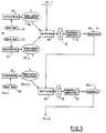
- the hypothesis and processing of the above verification is carried out using sensor data obtained with the passage of time. Data from the sonar ring devices (14) and stereo cameras (12) are interpreted at different sampling times; sonar data is obtained in a shorter cycle time than stereo data. Since the above hypothesis generation and verification are done each time sensor data is obtained, hypothesis generation and verification are done based either only on sonar data or on both sonar and stereo data. Each sensor data item is obtained continuously along with mobile robot movement.
- both sonar and stereo data can be obtained at time t K , presumed where hypothesis generation and verification are done.
- Sonar data (60) are obtained within the scope of distance measurement (detection region Sr in Figure 4).
- Stereo data (62) are obtained within the scope of the visual range (detection region Vi in Figure 4).
- Sonar data item (60) and stereo data item (62) provide a plurality of surface components. Attributes are then attached to all interpretation data S k,i and V k,j which indicate whether data is adopted in the hypothesis or already discarded at that point. In other words, interpretation data S k,i and V k,i are integrated to verify hypothesis H k-1 immediately before integration. When, next, verification (68) is done, a determination is made as to whether hypothesis H k-1 agrees with the surface component formed by sonar and stereo data, with the result that the part of hypothesis H k-1 which does not agree with the surface component is discarded, yielding data (70) which integrates the remainder of (agreed) hypothesis H k-1 and current interpretation data S k-i and V k,i .
- hypothesis generation (72) is done to generate new hypothesis H K .
- hypothesis H k interpretation data S k,i and V k,i are associated to clarify which interpretation is reflected.
- any prior hypothesis is null so that only integration of interpretation data S o,i and interpretation data V o,j obtained from detected sensor data generates hypothesis H0.
- sonar data are obtained in a shorter cycle time than stereo data, as described above.
- hypothesis generation and verification are done based only on sonar data.
- interpretation (64) is made using obtained sonar data (60) to yield interpretation data S k+1, i , interpreted as a surface component.
- interpretation data S k+1, i is used to verify hypothesis H k at time t k immediately before integration. In other words, a determination is made whether or not hypothesis H k agrees with the surface component formed by sonar and stereo data assumed from the hypothesis immediately before integration.
- hypothesis generation (72) is done using integrated data (70) to generate a new hypothesis.
- interpretation data S k+1,i are associated to clarify which is reflected.
- hypothesis verification and generation are done with the passage of time.
- a new hypothesis reflecting the previous hypothesis using a flat surface extended from hypothesis (76) given as the previous flat surface is then generated. As shown in Table 1, even when no surface is interpreted from stereo data with respect to the hypothesis at this time, interpretation is made with respect to the glass surface, thus concluding the surface for the interpretation of each sonar device.
- surface component (74) for the top end of the projecting surface in the hypothesis generated by sonar data can be also obtained at position P2 after mobile robot movement (10), and three-dimensional line segment (72) is obtained from stereo data so that previous hypothesis (76) is verified to be correct.
- surface component (74) at the top end of the projecting surface can be obtained from sonar data from one sonar device, and opposing surface components (74A) and (74B) can be obtained from sonar data from another sonar device.
- Three-dimensional line segment (72) can also be obtained from stereo data. Therefore, similar to the verification of a flat surface, three-dimensional line segment (72), surface component (74), and other surface components (74A) and (74B) correspond to previous hypothesis (76), so that hypothesis (76), that the surface is the recessed surface generated previously, is verified to be correct.
- the hypothesis is generated from stereo vision from the stereo cameras and sensor data obtained from each sonar device using sonar ring devices to verify the hypothesis from stereo data after movement and an interpretation from sonar data. It is then determined whether the hypothesis is adopted or not. If the hypothesis is discarded, a new hypothesis is generated. Even when the hypothesis is generated, new data is added and the hypothesis is expanded with the new data included.
- a hypothesis is then generated from the interpretation obtained from a plurality of different data with the result that, even if the first hypothesis is ambiguous, an environment can be detected from an angle different from the first with the movement of the mobile robot.
- a hypothesis with high certainty can then be obtained by verifying data obtained with the passage of time. An obstacle can then be detected before the mobile robot attains the point nearest to the obstacle, thereby enabling safe, efficient robot movement.
- Sensor data obtained by a plurality of different sensors is integrated to enable overall recognition of the environment and an easy understanding of the real-time run environment in actual mobile robot movement.
- This embodiment is intended for mobile robot movement by emphasizing the recognition of whether or not an object surface is present on the route or a nearby area such that an object is in the way of mobile robot movement. Strict environment recognition is needed to determine what the object is. Unlike in active sensing, movement is not confirmed for an ambiguous interpretation. Interpretation is renewed based on data obtained in avoidance movement. Even when the interpretation remains ambiguous, the object is avoided, and data on the route point passed by the mobile robot is discarded. Thus, sensor detection data is done in real time in mobile robot movement.
- distance and direction meters use data, but the present invention is not limited to such cases. Only sensor data obtained by the sonar ring devices and stereo cameras may also be used to determine distance and direction.
- the above hypothesis verification device is effective with a mobile robot which determines the movement region in advance for free movement in the region while preparing an environment map.
- the present invention can be applied to a mobile robot which can run independently by designating the predetermined area with starting and end points to move independently and for the shortest distance.
Applications Claiming Priority (2)
| Application Number | Priority Date | Filing Date | Title |
|---|---|---|---|
| JP5266647A JP2501010B2 (ja) | 1993-10-25 | 1993-10-25 | 移動ロボットの誘導装置 |
| JP266647/93 | 1993-10-25 |
Publications (2)
| Publication Number | Publication Date |
|---|---|
| EP0649709A2 true EP0649709A2 (de) | 1995-04-26 |
| EP0649709A3 EP0649709A3 (de) | 1996-05-29 |
Family
ID=17433741
Family Applications (1)
| Application Number | Title | Priority Date | Filing Date |
|---|---|---|---|
| EP94307828A Withdrawn EP0649709A3 (de) | 1993-10-25 | 1994-10-25 | Gerät zur Bewegung eines mobilen Roboters. |
Country Status (4)
| Country | Link |
|---|---|
| US (1) | US5525882A (de) |
| EP (1) | EP0649709A3 (de) |
| JP (1) | JP2501010B2 (de) |
| CA (1) | CA2132359A1 (de) |
Cited By (4)
| Publication number | Priority date | Publication date | Assignee | Title |
|---|---|---|---|---|
| GB2344888A (en) * | 1998-12-18 | 2000-06-21 | Notetry Ltd | Obstacle detection system |
| EP1548532A1 (de) * | 2002-10-01 | 2005-06-29 | Fujitsu Limited | Roboter |
| EP2395408A3 (de) * | 2010-06-10 | 2013-01-02 | Kabushiki Kaisha Yaskawa Denki | Bewegliches Körpersystem |
| CN105425794A (zh) * | 2015-11-25 | 2016-03-23 | 哈尔滨工业大学 | 一种移动机器人寻找放射源轨迹的方法 |
Families Citing this family (46)
| Publication number | Priority date | Publication date | Assignee | Title |
|---|---|---|---|---|
| IL113913A (en) | 1995-05-30 | 2000-02-29 | Friendly Machines Ltd | Navigation method and system |
| US5819008A (en) * | 1995-10-18 | 1998-10-06 | Rikagaku Kenkyusho | Mobile robot sensor system |
| US5978504A (en) * | 1997-02-19 | 1999-11-02 | Carnegie Mellon University | Fast planar segmentation of range data for mobile robots |
| EP1082702B1 (de) * | 1999-03-31 | 2017-10-18 | Koninklijke Philips N.V. | Verfahren zur bestimmung der verschiebung eines pixelblocks von einem ersten bild auf ein zweites bild einer szene |
| CA2369648A1 (en) * | 1999-04-16 | 2000-10-26 | Matsushita Electric Industrial Co., Limited | Image processing device and monitoring system |
| JP2001191283A (ja) * | 1999-12-31 | 2001-07-17 | Sony Corp | ロボット装置及びその制御方法 |
| JP4658787B2 (ja) * | 2000-02-21 | 2011-03-23 | シャープ株式会社 | 画像合成装置 |
| JP4672175B2 (ja) * | 2000-05-26 | 2011-04-20 | 本田技研工業株式会社 | 位置検出装置、位置検出方法、及び位置検出プログラム |
| SE0004466D0 (sv) * | 2000-12-04 | 2000-12-04 | Abb Ab | Mobile Robot |
| SE0004465D0 (sv) * | 2000-12-04 | 2000-12-04 | Abb Ab | Robot system |
| JP4087104B2 (ja) * | 2001-11-20 | 2008-05-21 | シャープ株式会社 | 群ロボットシステム |
| US6728608B2 (en) | 2002-08-23 | 2004-04-27 | Applied Perception, Inc. | System and method for the creation of a terrain density model |
| JP2004085337A (ja) * | 2002-08-27 | 2004-03-18 | Fujitsu Ltd | 車両検出方法及び車両検出装置 |
| US7774158B2 (en) | 2002-12-17 | 2010-08-10 | Evolution Robotics, Inc. | Systems and methods for landmark generation for visual simultaneous localization and mapping |
| JP3879848B2 (ja) * | 2003-03-14 | 2007-02-14 | 松下電工株式会社 | 自律移動装置 |
| US7689321B2 (en) * | 2004-02-13 | 2010-03-30 | Evolution Robotics, Inc. | Robust sensor fusion for mapping and localization in a simultaneous localization and mapping (SLAM) system |
| KR100561863B1 (ko) * | 2004-02-19 | 2006-03-16 | 삼성전자주식회사 | 가상 센서를 이용한 로봇의 네비게이션 방법 및 장치 |
| CA2505715A1 (en) * | 2004-05-03 | 2005-11-03 | Her Majesty In Right Of Canada As Represented By The Minister Of National Defence | Volumetric sensor for mobile robotics |
| CN100434915C (zh) * | 2004-05-28 | 2008-11-19 | 哈尔滨工程大学 | 采用水下机器人对堤坝隐患的检测方法 |
| US7840308B2 (en) * | 2004-09-10 | 2010-11-23 | Honda Motor Co., Ltd. | Robot device control based on environment and position of a movable robot |
| JP2006239844A (ja) * | 2005-03-04 | 2006-09-14 | Sony Corp | 障害物回避装置、障害物回避方法及び障害物回避プログラム並びに移動型ロボット装置 |
| US10705533B1 (en) | 2005-05-31 | 2020-07-07 | Richard Anthony Bishel | Autonomous lawnmower |
| JP5112666B2 (ja) * | 2006-09-11 | 2013-01-09 | 株式会社日立製作所 | 移動装置 |
| JP4990013B2 (ja) | 2007-04-18 | 2012-08-01 | 三菱電機株式会社 | 監視装置 |
| WO2008154408A1 (en) * | 2007-06-06 | 2008-12-18 | Tobey Wayland E | Modular hybrid snake arm |
| EP2045624A1 (de) * | 2007-10-01 | 2009-04-08 | Samsung Electronics Co., Ltd. | Ultraschall-Distanzsensor und Reinigungsroboter damit |
| US8213706B2 (en) * | 2008-04-22 | 2012-07-03 | Honeywell International Inc. | Method and system for real-time visual odometry |
| US8238612B2 (en) * | 2008-05-06 | 2012-08-07 | Honeywell International Inc. | Method and apparatus for vision based motion determination |
| US8275506B1 (en) | 2008-06-08 | 2012-09-25 | Richard Anthony Bishel | Boundary sensor |
| TWM348676U (en) * | 2008-07-22 | 2009-01-11 | Iner Aec Executive Yuan | Environmental survey robot |
| US8755997B2 (en) * | 2008-07-30 | 2014-06-17 | Honeywell International Inc. | Laser ranging process for road and obstacle detection in navigating an autonomous vehicle |
| US8364334B2 (en) * | 2008-10-30 | 2013-01-29 | Honeywell International Inc. | System and method for navigating an autonomous vehicle using laser detection and ranging |
| US8364309B1 (en) * | 2009-07-14 | 2013-01-29 | Bailey Bendrix L | User-assisted robot navigation system |
| US8325061B2 (en) * | 2010-01-07 | 2012-12-04 | Emilcott Associates, Inc. | System and method for mobile environmental measurements and displays |
| JP2011008791A (ja) * | 2010-06-30 | 2011-01-13 | Advanced Telecommunication Research Institute International | ロボットの対象物認識方法 |
| US20120195491A1 (en) * | 2010-07-21 | 2012-08-02 | Palo Alto Research Center Incorporated | System And Method For Real-Time Mapping Of An Indoor Environment Using Mobile Robots With Limited Sensing |
| AU2011305154B2 (en) | 2010-09-24 | 2015-02-05 | Irobot Corporation | Systems and methods for VSLAM optimization |
| JP5776332B2 (ja) * | 2011-05-27 | 2015-09-09 | 富士通株式会社 | 地図処理方法及びプログラム、並びにロボットシステム |
| US8798840B2 (en) | 2011-09-30 | 2014-08-05 | Irobot Corporation | Adaptive mapping with spatial summaries of sensor data |
| JP2015500746A (ja) * | 2011-12-09 | 2015-01-08 | ダイムラー・アクチェンゲゼルシャフトDaimler AG | 製造プラントの運転方法 |
| US9020637B2 (en) | 2012-11-02 | 2015-04-28 | Irobot Corporation | Simultaneous localization and mapping for a mobile robot |
| US9037396B2 (en) | 2013-05-23 | 2015-05-19 | Irobot Corporation | Simultaneous localization and mapping for a mobile robot |
| DE102016101552A1 (de) * | 2016-01-28 | 2017-08-03 | Vorwerk & Co. Interholding Gmbh | Verfahren zum Erstellen einer Umgebungskarte für ein selbsttätig verfahrbares Bearbeitungsgerät |
| JP6697281B2 (ja) * | 2016-02-10 | 2020-05-20 | 株式会社Soken | 物体検知装置 |
| US20190126490A1 (en) * | 2017-10-26 | 2019-05-02 | Ca, Inc. | Command and control interface for collaborative robotics |
| US11526182B2 (en) | 2019-03-25 | 2022-12-13 | Cbn Nano Technologies Inc. | Sensing and operation of devices in viscous flow using derived parameters to reduce data-handling requirements |
Family Cites Families (3)
| Publication number | Priority date | Publication date | Assignee | Title |
|---|---|---|---|---|
| JPS6084610A (ja) * | 1983-10-17 | 1985-05-14 | Hitachi Ltd | 誘導装置 |
| JPS61183716A (ja) * | 1985-02-08 | 1986-08-16 | Hitachi Ltd | 誘導装置 |
| US4954962A (en) * | 1988-09-06 | 1990-09-04 | Transitions Research Corporation | Visual navigation and obstacle avoidance structured light system |
-
1993
- 1993-10-25 JP JP5266647A patent/JP2501010B2/ja not_active Expired - Fee Related
-
1994
- 1994-09-19 CA CA002132359A patent/CA2132359A1/en not_active Abandoned
- 1994-10-24 US US08/328,030 patent/US5525882A/en not_active Expired - Fee Related
- 1994-10-25 EP EP94307828A patent/EP0649709A3/de not_active Withdrawn
Non-Patent Citations (5)
| Title |
|---|
| PROCEEDINGS OF THE 1993 IEEE/RSJ INTERNATIONAL CONFERENCE ON INTELLIGENT ROBOTS AND SYSTEMS, YOKOHAMA, JAPAN, 26-30 JULY 1993, INSTITUTE OF ELECTRICAL AND ELECTRONICS ENGINEERS, pages 1201-1207, XP 000447572 HEIKKILA T. ET AL. 'A SKILLED AND INTELLIGENT PAPER ROLL MANIPULATOR' * |
| PROCEEDINGS OF THE 1993 IEEE/RSJ INTERNATIONAL CONFERENCE ON INTELLIGENT ROBOTS AND SYSTEMS, YOKOHAMA, JAPAN, 26-30 JULY 1993, INSTITUTE OF ELECTRICAL AND ELECTRONICS ENGINEERS, pages 1793-1799, XP 000452452 NILSSON A. ET AL. 'ROBOT-SENSOR SYSTEM INTEGRATION BY MEANS OF 2-D VISION AND ULTRASONIC SENSING FOR LOCALISATION AND RECOGNITION OF OBJECTS' * |
| PROCEEDINGS OF THE IEEE/RSJ INTERNATIONAL CONFERENCE ON INTELLIGENT ROBOTS AND SYSTEMS, RALEIGH, NC., USA, 7 - 10 JULY, 1992, vol. 2, INSTITUTE OF ELECTRICAL AND ELECTRONICS ENGINEERS, pages 1147-1154, XP 000334072 HOLMBOM P. ET AL. 'MULTI-SENSOR INTEGRATION - THE SENSOR-GUIDED WINE SERVER' * |
| PROCEEDINGS OF THE INTERNATIONAL CONFERENCE ON ROBOTICS AND AUTOMATION, ATLANTA, GEORGIA, USA, 2 -6 MAY 1993, vol. 2, INSTITUTE OF ELECTRICAL AND ELECTRONICS ENGINEERS, pages 788-794, XP 000402737 HOLLIDAY M. ET AL. 'DEMONSTRATION OF AUTOMATED ROBOTIC WORKCELL FOR HAZARDOUS WASTE CHARACTERIZATION' * |
| PROCEEDINGS OF THE INTERNATIONAL CONFERENCE ON ROBOTICS AND AUTOMATION, NICE, FR, 12 - 14 MAY 1992, INSTITUTE OF ELECTRICAL AND ELECTRONICS ENGINEERS, pages 2018-2025, XP 000300001 VISCHER D. 'COOPERATING ROBOT WITH VISUAL AND TACTILE SKILLS' * |
Cited By (9)
| Publication number | Priority date | Publication date | Assignee | Title |
|---|---|---|---|---|
| GB2344888A (en) * | 1998-12-18 | 2000-06-21 | Notetry Ltd | Obstacle detection system |
| GB2353095A (en) * | 1998-12-18 | 2001-02-14 | Notetry Ltd | Autonomous vacuum cleaner with top-mounted, side-looking obstacle sensor |
| GB2353095B (en) * | 1998-12-18 | 2003-08-20 | Notetry Ltd | Sensors |
| EP1548532A1 (de) * | 2002-10-01 | 2005-06-29 | Fujitsu Limited | Roboter |
| EP1548532A4 (de) * | 2002-10-01 | 2007-08-08 | Fujitsu Ltd | Roboter |
| EP2557469A1 (de) * | 2002-10-01 | 2013-02-13 | Fujitsu Limited | Roboter |
| EP2395408A3 (de) * | 2010-06-10 | 2013-01-02 | Kabushiki Kaisha Yaskawa Denki | Bewegliches Körpersystem |
| US8548665B2 (en) | 2010-06-10 | 2013-10-01 | Kabushiki Kaisha Yaskawa Denki | Movable body system |
| CN105425794A (zh) * | 2015-11-25 | 2016-03-23 | 哈尔滨工业大学 | 一种移动机器人寻找放射源轨迹的方法 |
Also Published As
| Publication number | Publication date |
|---|---|
| EP0649709A3 (de) | 1996-05-29 |
| CA2132359A1 (en) | 1995-04-26 |
| JP2501010B2 (ja) | 1996-05-29 |
| US5525882A (en) | 1996-06-11 |
| JPH07116981A (ja) | 1995-05-09 |
Similar Documents
| Publication | Publication Date | Title |
|---|---|---|
| EP0649709A2 (de) | Gerät zur Bewegung eines mobilen Roboters | |
| US6678394B1 (en) | Obstacle detection system | |
| US6732826B2 (en) | Robot cleaner, robot cleaning system and method for controlling same | |
| US5249035A (en) | Method of measuring three dimensional shape | |
| US11602850B2 (en) | Method for identifying moving object in three-dimensional space and robot for implementing same | |
| CN110503040B (zh) | 障碍物检测方法及装置 | |
| WO2020258721A1 (zh) | 智能巡航车导航方法及系统 | |
| US7706572B2 (en) | Obstacle detection system and method therefor | |
| US20030063776A1 (en) | Walking auxiliary for person with impaired vision | |
| US7379389B2 (en) | Apparatus for monitoring surroundings of vehicle and sensor unit | |
| US20040066500A1 (en) | Occupancy detection and measurement system and method | |
| Nüchter et al. | Planning robot motion for 3d digitalization of indoor environments | |
| US11769267B2 (en) | Object distance measurement apparatus and method | |
| JPH032513A (ja) | 自動測量装置 | |
| JP4333611B2 (ja) | 移動体用の障害物検出装置 | |
| JPH07120555A (ja) | 車両用環境認識装置 | |
| US7286688B2 (en) | Object detection apparatus, distance measuring apparatus and object detection method | |
| Blais et al. | Optical range image acquisition for the navigation of a mobile robot | |
| WO2022179207A1 (zh) | 视窗遮挡检测方法及装置 | |
| JP2017142171A (ja) | 物体検知装置 | |
| CN102401901B (zh) | 测距系统及测距方法 | |
| JP3070277B2 (ja) | 先行車両検出装置 | |
| US20210018596A1 (en) | Method and device for identifying objects detected by a lidar device | |
| JP2854805B2 (ja) | 物体認識方法および視覚装置 | |
| KR20220146617A (ko) | 라이다 측정에서 블루밍을 검출하는 방법 및 장치 |
Legal Events
| Date | Code | Title | Description |
|---|---|---|---|
| PUAI | Public reference made under article 153(3) epc to a published international application that has entered the european phase |
Free format text: ORIGINAL CODE: 0009012 |
|
| AK | Designated contracting states |
Kind code of ref document: A2 Designated state(s): DE FR GB |
|
| 17P | Request for examination filed |
Effective date: 19950810 |
|
| PUAL | Search report despatched |
Free format text: ORIGINAL CODE: 0009013 |
|
| AK | Designated contracting states |
Kind code of ref document: A3 Designated state(s): DE FR GB |
|
| STAA | Information on the status of an ep patent application or granted ep patent |
Free format text: STATUS: THE APPLICATION HAS BEEN WITHDRAWN |
|
| 18W | Application withdrawn |
Withdrawal date: 19960826 |