EP0648670A1 - Propulsion system - Google Patents
Propulsion system Download PDFInfo
- Publication number
- EP0648670A1 EP0648670A1 EP94850180A EP94850180A EP0648670A1 EP 0648670 A1 EP0648670 A1 EP 0648670A1 EP 94850180 A EP94850180 A EP 94850180A EP 94850180 A EP94850180 A EP 94850180A EP 0648670 A1 EP0648670 A1 EP 0648670A1
- Authority
- EP
- European Patent Office
- Prior art keywords
- propeller
- rudder
- hood
- propulsion system
- section
- Prior art date
- Legal status (The legal status is an assumption and is not a legal conclusion. Google has not performed a legal analysis and makes no representation as to the accuracy of the status listed.)
- Granted
Links
Images

Classifications
-
- B—PERFORMING OPERATIONS; TRANSPORTING
- B63—SHIPS OR OTHER WATERBORNE VESSELS; RELATED EQUIPMENT
- B63H—MARINE PROPULSION OR STEERING
- B63H5/00—Arrangements on vessels of propulsion elements directly acting on water
- B63H5/07—Arrangements on vessels of propulsion elements directly acting on water of propellers
- B63H5/16—Arrangements on vessels of propulsion elements directly acting on water of propellers characterised by being mounted in recesses; with stationary water-guiding elements; Means to prevent fouling of the propeller, e.g. guards, cages or screens
-
- B—PERFORMING OPERATIONS; TRANSPORTING
- B63—SHIPS OR OTHER WATERBORNE VESSELS; RELATED EQUIPMENT
- B63H—MARINE PROPULSION OR STEERING
- B63H25/00—Steering; Slowing-down otherwise than by use of propulsive elements; Dynamic anchoring, i.e. positioning vessels by means of main or auxiliary propulsive elements
- B63H25/06—Steering by rudders
- B63H25/38—Rudders
Definitions
- the present invention relates to a propulsion system, particularly for high-speed boats, consisting of a propeller having a propeller hood positioned downstream relative to the propeller blades, and a rudder.
- the present invention is particularly suitable for use in connection with a propulsion system wherein an inclined propeller shaft is employed. This should not, however, be seen as a limitation to the application of the invention.
- propeller shaft 1 is suspended in a bracket 2, and the propeller itself 3 terminates in a propeller hood 4.
- Propeller shaft 1 is angled relative to the boat hull 5 at an angle of ⁇ relative to the structural water line 6 of the boat.
- the boat rudder 7, as shown on Figure 1, is positioned downstream in relation to both the propeller blades 3 and the actual propeller hood 4.
- Rudder 7 has a streamlined configuration, i.e., having an outwardly curved surface on each side thereof.
- the present invention therefore aims to reduce or eliminate the suction behind the propeller hood, at the same time as it seeks to improve the rudder effect with respect to recovery of rotational loss behind the propeller.
- the propulsion system mentioned in the introduction above is characterized in that the propeller hood extends entirely or partially along the lower edge of the rudder, and that the rudder has approximately the same cross section as an airfoil or aircraft wing.
- the propeller hood is shaped like a cone.
- the propeller hood may be designed as a rotating body the generatrix of which forms a curve.
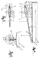
- Figure 1 is a view of a propulsion system according to the prior art.
- Figure 2 is a view of section II-II in Figure 1.
- Figure 3 is an elevational end view of section III in Figure 1.
- Figure 4 is a side view of the propulsion system in accordance with the present invention.
- Figure 5 is a view of section V-V in Figure 4.
- Figure 6 is an elevational view of section VI in Figure 1.
- FIG. 4 illustrates the way propeller shaft 1 extends from a sleeve bearing 8 in the hull 5, similarly to what is also shown in Figure 1.
- propeller shaft 1 is mounted in a propeller bracket or sleeve bearing 2 in the same manner as illustrated in connection with Figure 1.
- the propeller is designated with reference numeral 3.
- the actual propeller hood, according to the invention, is preferably cone shaped, and is indicated by reference numeral 4'in Figures 4 and 5.
- the rudder extending downward from boat hull 5 is indicated by reference numeral 7. This rudder is specially designed to have the approximate cross section of an airfoil or aircraft wing, imparting rudder 7' with a pressure side 8 and a suction side 9.
- propeller hood 4' extends completely or partially along the lower edge of rudder 7'.
- the rudder will have approximately the same cross section as an aircraft wing or airfoil.
- the slip stream produced behind the propeller will rotate in the same rotational direction as the propeller, as shown inter alia by Figure 6. This will in turn cause the water stream to impact rudder 7' at a slant.
- the rudder thus acquires a pressure side 8 and a suction side 9 when set at its center position, as shown in Figures 5 and 6.
- the overpressure on the one side may be increased if the rudder is designed as shown, i.e., like an airfoil or aircraft wing. This pressure will be transmitted down to propeller hood 4'.
- the circulation around the propeller hood will have the opposite direction of rotation as the slip stream behind the propeller. This will have the result of counteracting turbulence, thereby decreasing the power loss. Propeller 3 will thereby achieve a greater thrusting power, which may be utilized to attain higher speed or a lower power consumption.
- the forces generated against the rudder could be equalized by having a propeller rotating in the opposite direction on twin-propeller boats, or by rotating the rudder sections above the propeller, thus counterbalancing the steering forces on boats having one propeller.
- the present propulsion system has proven during testing that it is possible to achieve power gains of a magnitude of between 10% and 15% compared with the known art, cf. Figures 1-3.
Landscapes
- Chemical & Material Sciences (AREA)
- Engineering & Computer Science (AREA)
- Combustion & Propulsion (AREA)
- Mechanical Engineering (AREA)
- Ocean & Marine Engineering (AREA)
- Control Of Position Or Direction (AREA)
- Control Of Linear Motors (AREA)
- Control Of Position, Course, Altitude, Or Attitude Of Moving Bodies (AREA)
- Valve Device For Special Equipments (AREA)
- Structures Of Non-Positive Displacement Pumps (AREA)
- Reciprocating, Oscillating Or Vibrating Motors (AREA)
- Portable Nailing Machines And Staplers (AREA)
- Transmission Devices (AREA)
- Vehicle Body Suspensions (AREA)
Abstract
Description
- The present invention relates to a propulsion system, particularly for high-speed boats, consisting of a propeller having a propeller hood positioned downstream relative to the propeller blades, and a rudder.
- The present invention is particularly suitable for use in connection with a propulsion system wherein an inclined propeller shaft is employed. This should not, however, be seen as a limitation to the application of the invention.
- In a conventional propulsion system as shown, for example, on the attached Figures 1, 2 and 3, particularly for high-speed boats having an
inclined propeller shaft 1, the propeller shaft is suspended in abracket 2, and the propeller itself 3 terminates in apropeller hood 4.Propeller shaft 1 is angled relative to theboat hull 5 at an angle of α relative to the structural water line 6 of the boat. - The
boat rudder 7, as shown on Figure 1, is positioned downstream in relation to both thepropeller blades 3 and theactual propeller hood 4. Rudder 7 has a streamlined configuration, i.e., having an outwardly curved surface on each side thereof. - At high speeds suction will be generated at the after edge of
propeller hood 4. Such suction will substantially reduce the effect ofpropeller 3. The propeller will also establish rotation in the slip stream behind the propeller. This, too, represents a significant power loss. Such rotational loss may be partially recovered in the rudder. - The present invention therefore aims to reduce or eliminate the suction behind the propeller hood, at the same time as it seeks to improve the rudder effect with respect to recovery of rotational loss behind the propeller.
- According to the invention, therefore, the propulsion system mentioned in the introduction above is characterized in that the propeller hood extends entirely or partially along the lower edge of the rudder, and that the rudder has approximately the same cross section as an airfoil or aircraft wing.
- According to an embodiment form of the propulsion system, the propeller hood is shaped like a cone. Alternatively, the propeller hood may be designed as a rotating body the generatrix of which forms a curve.
- The invention will now be described in more detail with reference to the appended drawings.
- Figure 1 is a view of a propulsion system according to the prior art.
- Figure 2 is a view of section II-II in Figure 1.
- Figure 3 is an elevational end view of section III in Figure 1.
- Figure 4 is a side view of the propulsion system in accordance with the present invention.
- Figure 5 is a view of section V-V in Figure 4.
- Figure 6 is an elevational view of section VI in Figure 1.
- Figure 4 illustrates the
way propeller shaft 1 extends from a sleeve bearing 8 in thehull 5, similarly to what is also shown in Figure 1. In the depicted embodiment,propeller shaft 1 is mounted in a propeller bracket or sleeve bearing 2 in the same manner as illustrated in connection with Figure 1. As in Figure 1, the propeller is designated withreference numeral 3. The actual propeller hood, according to the invention, is preferably cone shaped, and is indicated by reference numeral 4'in Figures 4 and 5. The rudder extending downward fromboat hull 5 is indicated byreference numeral 7. This rudder is specially designed to have the approximate cross section of an airfoil or aircraft wing, imparting rudder 7' with apressure side 8 and asuction side 9. - In the known solution, as indicated in Figure 2, a rotating
slip stream 10 is generated behind the propeller, and this has a detrimental effect on the overall effect of the propulsion system. - As will be apparent from Figure 4, propeller hood 4' extends completely or partially along the lower edge of rudder 7'. As mentioned above, the rudder will have approximately the same cross section as an aircraft wing or airfoil. The slip stream produced behind the propeller will rotate in the same rotational direction as the propeller, as shown inter alia by Figure 6. This will in turn cause the water stream to impact rudder 7' at a slant. The rudder thus acquires a
pressure side 8 and asuction side 9 when set at its center position, as shown in Figures 5 and 6. The overpressure on the one side may be increased if the rudder is designed as shown, i.e., like an airfoil or aircraft wing. This pressure will be transmitted down to propeller hood 4'. As a result of the pressure difference, water will flow around propeller hood 4' to thesuction side 9 of the rudder. This will then increase the pressure around the entire propeller hood 4'. The suction that would be generated against the propeller hood in accordance with the known art would be partially or completely eliminated according to the present invention. - The circulation around the propeller hood will have the opposite direction of rotation as the slip stream behind the propeller. This will have the result of counteracting turbulence, thereby decreasing the power loss.
Propeller 3 will thereby achieve a greater thrusting power, which may be utilized to attain higher speed or a lower power consumption. - The forces generated against the rudder could be equalized by having a propeller rotating in the opposite direction on twin-propeller boats, or by rotating the rudder sections above the propeller, thus counterbalancing the steering forces on boats having one propeller.
- As will be apparent from Figure 4, a small clearance k between propeller hood 4' and rudder 7' will be necessary to permit rudder 7' to move relative to the rotating propeller hood 4'.
- As will be apparent from Figure 5, the motion of slip stream 10' will be more rectilinear than the rotation that occurs in the embodiment shown in Figure 2.
- In Figure 6 the water circulation below rudder 7' is designated by
reference numeral 11, andreference numeral 12 indicates the direction of rotation of the propeller. - The present propulsion system has proven during testing that it is possible to achieve power gains of a magnitude of between 10% and 15% compared with the known art, cf. Figures 1-3.
Claims (3)
- A propulsion system, particularly for high-speed boats (5), consisting of a propeller (3) having a propeller hood (4') positioned downstream relative to the blades of the propeller (3), and a rudder, characterized in that the propeller hood (4') extends entirely or partially along the lower edge of the rudder (7'), and that the rudder has approximately the same cross section as an airfoil or aircraft wing.
- A propulsion system as disclosed in claim 1,
characterized in that the propeller hood (4') is shaped like a cone. - The propulsion system as disclosed in claim 1,
characterized in that the propeller hood (4') is designed as a rotating body the generatrix of which forms a curve.
Applications Claiming Priority (2)
| Application Number | Priority Date | Filing Date | Title |
|---|---|---|---|
| NO933744 | 1993-10-18 | ||
| NO933744A NO178103C (en) | 1993-10-18 | 1993-10-18 | propulsion system |
Publications (2)
| Publication Number | Publication Date |
|---|---|
| EP0648670A1 true EP0648670A1 (en) | 1995-04-19 |
| EP0648670B1 EP0648670B1 (en) | 1998-01-14 |
Family
ID=19896512
Family Applications (1)
| Application Number | Title | Priority Date | Filing Date |
|---|---|---|---|
| EP94850180A Expired - Lifetime EP0648670B1 (en) | 1993-10-18 | 1994-10-14 | Propulsion system |
Country Status (5)
| Country | Link |
|---|---|
| EP (1) | EP0648670B1 (en) |
| AT (1) | ATE162146T1 (en) |
| AU (1) | AU7591294A (en) |
| DE (1) | DE69407918D1 (en) |
| NO (1) | NO178103C (en) |
Citations (6)
| Publication number | Priority date | Publication date | Assignee | Title |
|---|---|---|---|---|
| GB191002182A (en) * | 1910-01-28 | 1910-12-31 | William Henry Fauber | Improvements in Rudders and Propeller Shaft Brackets. |
| GB293351A (en) * | 1927-07-04 | 1929-06-13 | Star Contrapropeller Ltd As | An arrangement of guide vanes in single-screw ships |
| US2064463A (en) * | 1933-03-18 | 1936-12-15 | Crosley Radio Corp | Motor boat and driving unit therefor |
| FR1549826A (en) * | 1967-12-26 | 1968-12-13 | ||
| FR2281269A1 (en) * | 1974-08-08 | 1976-03-05 | Schottel Werft | INSTALLATION OF A SHIP PROPELLER |
| GB2008520A (en) * | 1977-11-28 | 1979-06-06 | Skf Nova Ab | Propellers shrouds |
-
1993
- 1993-10-18 NO NO933744A patent/NO178103C/en unknown
-
1994
- 1994-10-14 EP EP94850180A patent/EP0648670B1/en not_active Expired - Lifetime
- 1994-10-14 DE DE69407918T patent/DE69407918D1/en not_active Expired - Lifetime
- 1994-10-14 AT AT94850180T patent/ATE162146T1/en not_active IP Right Cessation
- 1994-10-18 AU AU75912/94A patent/AU7591294A/en not_active Abandoned
Patent Citations (6)
| Publication number | Priority date | Publication date | Assignee | Title |
|---|---|---|---|---|
| GB191002182A (en) * | 1910-01-28 | 1910-12-31 | William Henry Fauber | Improvements in Rudders and Propeller Shaft Brackets. |
| GB293351A (en) * | 1927-07-04 | 1929-06-13 | Star Contrapropeller Ltd As | An arrangement of guide vanes in single-screw ships |
| US2064463A (en) * | 1933-03-18 | 1936-12-15 | Crosley Radio Corp | Motor boat and driving unit therefor |
| FR1549826A (en) * | 1967-12-26 | 1968-12-13 | ||
| FR2281269A1 (en) * | 1974-08-08 | 1976-03-05 | Schottel Werft | INSTALLATION OF A SHIP PROPELLER |
| GB2008520A (en) * | 1977-11-28 | 1979-06-06 | Skf Nova Ab | Propellers shrouds |
Also Published As
| Publication number | Publication date |
|---|---|
| ATE162146T1 (en) | 1998-01-15 |
| EP0648670B1 (en) | 1998-01-14 |
| NO178103C (en) | 1996-01-24 |
| AU7591294A (en) | 1995-05-04 |
| NO933744D0 (en) | 1993-10-18 |
| NO933744L (en) | 1995-04-19 |
| DE69407918D1 (en) | 1998-02-19 |
| NO178103B (en) | 1995-10-16 |
Similar Documents
| Publication | Publication Date | Title |
|---|---|---|
| CA1263825A (en) | Propeller combination for a boat propeller unit | |
| CA2286705C (en) | Improved fluid displacing blade | |
| CA2223901C (en) | Marine outdrive with surface piercing propeller and stabilizing shroud | |
| WO1992022459A1 (en) | Propulsive thrust ring system | |
| US5445100A (en) | Dual rudder system for trimming planing-type hulls | |
| JP2000511488A (en) | Marine propulsion and steering equipment | |
| JPS58194691A (en) | Water-current inducing surface of stern of screw propeller ship | |
| EP0648670B1 (en) | Propulsion system | |
| US4798547A (en) | Fuel efficient propulsor for outboard motors | |
| US5134954A (en) | Asymmetric hydrofoil propulsion method and apparatus | |
| EP0200749A1 (en) | Propellors for watercraft. | |
| CN1072146A (en) | Guiding device | |
| CA2419669A1 (en) | Boat thruster apparatus and method | |
| JP2513192B2 (en) | Stern section rectifier | |
| EP4129816A1 (en) | Stern bulbs | |
| JPS6013759Y2 (en) | rudder | |
| SU1576420A1 (en) | Shipъs rotary propeller system | |
| JPH0234160Y2 (en) | ||
| GB2101693A (en) | Ship's propellor blades | |
| JPH02274687A (en) | Single screw vessel with rectifying bilge keel | |
| AU708767C (en) | Improved fluid displacing blade | |
| RU2115588C1 (en) | Shipboard propulsion engine plant, type swinging propeller | |
| RU2081014C1 (en) | Flying wing ground-effect craft | |
| JPS604495A (en) | Ship with spherical stern | |
| NO172177B (en) | ENERGY EFFICIENT PROGRESS SYSTEM WITH MIRROR COVER AND PROPELLER AND PROCEDURE TO AA IMPROVE EFFICIENCY AND / OR REDUCE PROPELL-INDUCED HULL Vibration |
Legal Events
| Date | Code | Title | Description |
|---|---|---|---|
| PUAI | Public reference made under article 153(3) epc to a published international application that has entered the european phase |
Free format text: ORIGINAL CODE: 0009012 |
|
| AK | Designated contracting states |
Kind code of ref document: A1 Designated state(s): AT BE CH DE DK ES FR GB GR IE IT LI LU MC NL PT SE |
|
| RAX | Requested extension states of the european patent have changed |
Free format text: LT PAYMENT 941021;SI PAYMENT 941021 |
|
| 17P | Request for examination filed |
Effective date: 19951012 |
|
| GRAG | Despatch of communication of intention to grant |
Free format text: ORIGINAL CODE: EPIDOS AGRA |
|
| 17Q | First examination report despatched |
Effective date: 19970321 |
|
| GRAG | Despatch of communication of intention to grant |
Free format text: ORIGINAL CODE: EPIDOS AGRA |
|
| GRAH | Despatch of communication of intention to grant a patent |
Free format text: ORIGINAL CODE: EPIDOS IGRA |
|
| GRAH | Despatch of communication of intention to grant a patent |
Free format text: ORIGINAL CODE: EPIDOS IGRA |
|
| GRAA | (expected) grant |
Free format text: ORIGINAL CODE: 0009210 |
|
| AK | Designated contracting states |
Kind code of ref document: B1 Designated state(s): AT BE CH DE DK ES FR GB GR IE IT LI LU MC NL PT SE |
|
| AX | Request for extension of the european patent |
Free format text: LT PAYMENT 941021;SI PAYMENT 941021 |
|
| LTIE | Lt: invalidation of european patent or patent extension | ||
| PG25 | Lapsed in a contracting state [announced via postgrant information from national office to epo] |
Ref country code: LI Free format text: LAPSE BECAUSE OF FAILURE TO SUBMIT A TRANSLATION OF THE DESCRIPTION OR TO PAY THE FEE WITHIN THE PRESCRIBED TIME-LIMIT Effective date: 19980114 Ref country code: IT Free format text: LAPSE BECAUSE OF FAILURE TO SUBMIT A TRANSLATION OF THE DESCRIPTION OR TO PAY THE FEE WITHIN THE PRESCRIBED TIME-LIMIT;WARNING: LAPSES OF ITALIAN PATENTS WITH EFFECTIVE DATE BEFORE 2007 MAY HAVE OCCURRED AT ANY TIME BEFORE 2007. THE CORRECT EFFECTIVE DATE MAY BE DIFFERENT FROM THE ONE RECORDED. Effective date: 19980114 Ref country code: GR Free format text: LAPSE BECAUSE OF FAILURE TO SUBMIT A TRANSLATION OF THE DESCRIPTION OR TO PAY THE FEE WITHIN THE PRESCRIBED TIME-LIMIT Effective date: 19980114 Ref country code: FR Free format text: LAPSE BECAUSE OF FAILURE TO SUBMIT A TRANSLATION OF THE DESCRIPTION OR TO PAY THE FEE WITHIN THE PRESCRIBED TIME-LIMIT Effective date: 19980114 Ref country code: ES Free format text: THE PATENT HAS BEEN ANNULLED BY A DECISION OF A NATIONAL AUTHORITY Effective date: 19980114 Ref country code: CH Free format text: LAPSE BECAUSE OF FAILURE TO SUBMIT A TRANSLATION OF THE DESCRIPTION OR TO PAY THE FEE WITHIN THE PRESCRIBED TIME-LIMIT Effective date: 19980114 Ref country code: BE Free format text: LAPSE BECAUSE OF FAILURE TO SUBMIT A TRANSLATION OF THE DESCRIPTION OR TO PAY THE FEE WITHIN THE PRESCRIBED TIME-LIMIT Effective date: 19980114 Ref country code: AT Free format text: LAPSE BECAUSE OF FAILURE TO SUBMIT A TRANSLATION OF THE DESCRIPTION OR TO PAY THE FEE WITHIN THE PRESCRIBED TIME-LIMIT Effective date: 19980114 |
|
| REF | Corresponds to: |
Ref document number: 162146 Country of ref document: AT Date of ref document: 19980115 Kind code of ref document: T |
|
| REG | Reference to a national code |
Ref country code: CH Ref legal event code: EP |
|
| REF | Corresponds to: |
Ref document number: 69407918 Country of ref document: DE Date of ref document: 19980219 |
|
| PG25 | Lapsed in a contracting state [announced via postgrant information from national office to epo] |
Ref country code: PT Free format text: LAPSE BECAUSE OF FAILURE TO SUBMIT A TRANSLATION OF THE DESCRIPTION OR TO PAY THE FEE WITHIN THE PRESCRIBED TIME-LIMIT Effective date: 19980414 Ref country code: DK Free format text: LAPSE BECAUSE OF FAILURE TO SUBMIT A TRANSLATION OF THE DESCRIPTION OR TO PAY THE FEE WITHIN THE PRESCRIBED TIME-LIMIT Effective date: 19980414 |
|
| PG25 | Lapsed in a contracting state [announced via postgrant information from national office to epo] |
Ref country code: DE Free format text: LAPSE BECAUSE OF FAILURE TO SUBMIT A TRANSLATION OF THE DESCRIPTION OR TO PAY THE FEE WITHIN THE PRESCRIBED TIME-LIMIT Effective date: 19980415 |
|
| EN | Fr: translation not filed | ||
| REG | Reference to a national code |
Ref country code: IE Ref legal event code: FG4D Free format text: 78360 |
|
| REG | Reference to a national code |
Ref country code: CH Ref legal event code: PL |
|
| PG25 | Lapsed in a contracting state [announced via postgrant information from national office to epo] |
Ref country code: LU Free format text: LAPSE BECAUSE OF NON-PAYMENT OF DUE FEES Effective date: 19981014 Ref country code: IE Free format text: LAPSE BECAUSE OF NON-PAYMENT OF DUE FEES Effective date: 19981014 Ref country code: GB Free format text: LAPSE BECAUSE OF NON-PAYMENT OF DUE FEES Effective date: 19981014 |
|
| PLBE | No opposition filed within time limit |
Free format text: ORIGINAL CODE: 0009261 |
|
| STAA | Information on the status of an ep patent application or granted ep patent |
Free format text: STATUS: NO OPPOSITION FILED WITHIN TIME LIMIT |
|
| 26N | No opposition filed | ||
| PG25 | Lapsed in a contracting state [announced via postgrant information from national office to epo] |
Ref country code: MC Free format text: LAPSE BECAUSE OF NON-PAYMENT OF DUE FEES Effective date: 19990430 |
|
| GBPC | Gb: european patent ceased through non-payment of renewal fee |
Effective date: 19981014 |
|
| PGFP | Annual fee paid to national office [announced via postgrant information from national office to epo] |
Ref country code: NL Payment date: 19991014 Year of fee payment: 6 |
|
| PGFP | Annual fee paid to national office [announced via postgrant information from national office to epo] |
Ref country code: SE Payment date: 19991018 Year of fee payment: 6 |
|
| PG25 | Lapsed in a contracting state [announced via postgrant information from national office to epo] |
Ref country code: SE Free format text: THE PATENT HAS BEEN ANNULLED BY A DECISION OF A NATIONAL AUTHORITY Effective date: 20001030 |
|
| PG25 | Lapsed in a contracting state [announced via postgrant information from national office to epo] |
Ref country code: NL Free format text: LAPSE BECAUSE OF NON-PAYMENT OF DUE FEES Effective date: 20010501 |
|
| EUG | Se: european patent has lapsed |
Ref document number: 94850180.4 |
|
| NLV4 | Nl: lapsed or anulled due to non-payment of the annual fee |
Effective date: 20010501 |