EP0647988B1 - Steckverbinder-Kupplung - Google Patents
Steckverbinder-Kupplung Download PDFInfo
- Publication number
- EP0647988B1 EP0647988B1 EP94114145A EP94114145A EP0647988B1 EP 0647988 B1 EP0647988 B1 EP 0647988B1 EP 94114145 A EP94114145 A EP 94114145A EP 94114145 A EP94114145 A EP 94114145A EP 0647988 B1 EP0647988 B1 EP 0647988B1
- Authority
- EP
- European Patent Office
- Prior art keywords
- connector
- socket contacts
- plug
- socket
- male connector
- Prior art date
- Legal status (The legal status is an assumption and is not a legal conclusion. Google has not performed a legal analysis and makes no representation as to the accuracy of the status listed.)
- Expired - Lifetime
Links
- 230000008878 coupling Effects 0.000 claims description 9
- 238000010168 coupling process Methods 0.000 claims description 9
- 238000005859 coupling reaction Methods 0.000 claims description 9
- 238000003780 insertion Methods 0.000 claims description 5
- 230000037431 insertion Effects 0.000 claims description 5
- 239000011810 insulating material Substances 0.000 claims description 2
- 230000004308 accommodation Effects 0.000 claims 2
- 238000007789 sealing Methods 0.000 description 4
- 230000009993 protective function Effects 0.000 description 2
- 230000001960 triggered effect Effects 0.000 description 2
- 230000001133 acceleration Effects 0.000 description 1
- 239000003990 capacitor Substances 0.000 description 1
- 238000007599 discharging Methods 0.000 description 1
- 230000006870 function Effects 0.000 description 1
- 238000009434 installation Methods 0.000 description 1
- 230000007257 malfunction Effects 0.000 description 1
- 238000000034 method Methods 0.000 description 1
- 230000003068 static effect Effects 0.000 description 1
Images



Classifications
-
- H—ELECTRICITY
- H01—ELECTRIC ELEMENTS
- H01R—ELECTRICALLY-CONDUCTIVE CONNECTIONS; STRUCTURAL ASSOCIATIONS OF A PLURALITY OF MUTUALLY-INSULATED ELECTRICAL CONNECTING ELEMENTS; COUPLING DEVICES; CURRENT COLLECTORS
- H01R13/00—Details of coupling devices of the kinds covered by groups H01R12/70 or H01R24/00 - H01R33/00
- H01R13/648—Protective earth or shield arrangements on coupling devices, e.g. anti-static shielding
-
- H—ELECTRICITY
- H01—ELECTRIC ELEMENTS
- H01R—ELECTRICALLY-CONDUCTIVE CONNECTIONS; STRUCTURAL ASSOCIATIONS OF A PLURALITY OF MUTUALLY-INSULATED ELECTRICAL CONNECTING ELEMENTS; COUPLING DEVICES; CURRENT COLLECTORS
- H01R13/00—Details of coupling devices of the kinds covered by groups H01R12/70 or H01R24/00 - H01R33/00
- H01R13/66—Structural association with built-in electrical component
- H01R13/719—Structural association with built-in electrical component specially adapted for high frequency, e.g. with filters
- H01R13/7197—Structural association with built-in electrical component specially adapted for high frequency, e.g. with filters with filters integral with or fitted onto contacts, e.g. tubular filters
Definitions
- the invention relates to a connector coupling, with a socket plug and with a pin plug, which together form a pair of plugs and which consist of insulating material and each have receptacles for inserting and primarily securing socket contacts, at least one resilient shorting bridge being provided, each connects two socket contacts of the socket connector to one another, and the pin connector, in parallel to contact pins arranged in at least one row, which are intended for insertion into the correspondingly arranged socket contacts of the socket connector and are each connected to its own socket contacts, has an interrupter element for each shorting bridge, which at the coupling of the socket plug and pin plug cancels the short circuit between the two socket contacts.
- Such a connector is known from DE-U 91 12 178.
- Connectors are used, for example, as components of airbag systems in motor vehicles.
- the increasing demands on the operational safety of such systems inevitably trigger increasing demands on their connectors.
- connectors of this type must therefore perform important protective functions, in particular securing against malfunctions of the airbag system triggered by electrical charges when the connector is uncoupled and before being triggered incorrectly during operation by electromagnetic interference.
- the invention has for its object to provide an expanded, more compact and at the same time more flexible connector coupling of the type mentioned in its functions.
- an electrical filter component is integrated in the pin connector and is connected in series between two socket contacts of the plug pair which are connected to one another in the coupling.
- the connector shown in Figure 1 consists of a pin connector 1 and a socket connector 8, 9 and 15.
- pin contacts in the approximately cylindrical pin connector 1 are pin contacts in the axial direction, for example with a cross section of 0.63 x 0.63 mm and with a gold-plated contact surface, pressed in.
- the pin connector is a six-pole, two-row contact arrangement front cable outlet.
- the socket-side end of the pin connector 1 is open, so that the pin connector 1 is designed there for partially receiving the socket connector in the coupling.
- the coupling is supported by guide and locking means known per se, in particular a resilient locking hook 13 on the socket connector and a suitable locking opening 4 on the pin connector 1.
- An advantageous possibility of fixing the connector, for example on the vehicle chassis, is given by the integrated snap hook 2 shown.
- the pin connector 1 has towards the cable outlet end side towards two closable by a first and a second cover 5 and 6, approximately designed as a half-cylinder, which are provided for the separate reception of the filter component or the socket contacts 11.
- a series-connected coil 3 serving as a low-pass filter can preferably be used as the filter component.
- another component for example a capacitor or a wire, can also be connected.
- the coil 3 can be arranged transversely or parallel to the axial direction of the pin connector 1. It can also be easily encapsulated with plastic.
- the first closure cap 5 Chamber has a trough-like shape intended for receiving the somewhat smaller component, in which the component is resiliently held by at least one spring tab, shown in FIG. 4, formed on the inside of the first sealing cover 5.
- the first closure cover 5 provided with torsion locking hooks presses the coil 3 into the receptacle after it has been put on and locked into the pin connector 1
- the first sealing cap 5 cannot be removed again without using force. Vibrations are sufficiently dampened by pressing the coil through the spring tab.
- the second chamber of the pin connector 1, which cannot be seen downwards in the illustration selected in FIG. 1, is used primarily for receiving the socket contacts 11, for the base receptacles for insertion and window for primary securing of the socket contacts 11, which are preferably designed as a locking sleeve with spring tabs
- the secondary locking prescribed for safety reasons can advantageously take place by means of a crosspiece 7 formed on the inside of the second sealing cover 6 closing the second chamber, by means of which the socket contacts 11 of the pin connector 1 are finally secured when the sealing cover 6 is closed.
- To close the second cover 6 is inserted laterally on the pin connector 1 in hinges and pivoted. It engages via a snap-on hook molded onto the pin connector 1, but can be opened again for easier accessibility.
- the socket plug consists of a socket housing 9, which can be inserted into a cover cap 8 in a polarized manner, in which the socket contacts 10 and the at least one short-circuit bridge 12, shown in more detail in FIG. 6, are arranged, and an axially slidable cover plate 8 Locking plate 15.
- the socket housing 9 is provided with guide grooves 16, into which guide ribs 14 which are integrally formed on the cap 8 when inserted into the cover cap, a final securing of the socket contacts 10 being effected at the same time.
- locking lugs and corresponding recesses on the closure plate 15 are provided on the cover cap 8, incorrect insertion being avoided by a closed groove on the cover cap 8.
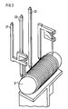
- FIG. 2 shows an interconnection of the contact pins 21, 22 and 23 with the filter coil according to the invention. It can be seen that the filter component is electrically connected to the angled ends of two contact pin parts 21 which, rotated and mirrored by 180 °, are laterally offset and arranged in a row with the other contact pins in the pin connector and fastened.
- This realization of the series connection is, in addition to the basic advantage of each embodiment according to the invention, to provide a series connection integrated in a single plug-in connector with a short-circuit element, in that two identical contact pin parts, which are however mounted asymmetrically, can be used, which in particular makes installation easy allows two identical operations.
- One of the contact paths short-circuited in the socket connector is usually provided with the series connection.
- the two other contact pins 22 and 23, one of which in the exemplary embodiment shown serves neither as a power supply nor ground connection, but rather as an optional connection option, are both directly inserted with their two ends into the socket contacts of the pin plug and the socket plug lying axially in a line, while the socket contacts connected to one another by the two contact pin parts 21 and the coil connected in series are slightly offset laterally, which considerably increases the scope for the arrangement of the coil or another filter component.
Landscapes
- Details Of Connecting Devices For Male And Female Coupling (AREA)
- Connector Housings Or Holding Contact Members (AREA)
- Mechanical Coupling Of Light Guides (AREA)
- Coupling Device And Connection With Printed Circuit (AREA)
Description
- Die Erfindung betrifft eine Steckverbinder-Kupplung, mit einem Buchsenstecker und mit einem Stiftstecker, die zusammen ein Stecker-Pärchen bilden und die aus Isoliermaterial bestehen und jeweils Aufnahmen zum Einstecken und primärem Sichern von Buchsenkontakten aufweisen, wobei mindestens eine federnde Kurzschlußbrücke vorgesehen ist, die jeweils zwei Buchsenkontakte des Buchsensteckers miteinander verbindet, und wobei der Stiftstecker, parallel zu in mindestens einer Reihe angeordneten Kontaktstiften, die zum Einstecken in die entsprechend angeordneten Buchsenkontakte des Buchsensteckers bestimmt und jeweils mit den eigenen Buchsenkontakten verbunden sind, für jede Kurzschlußbrücke ein Unterbrecherelement aufweist, welches bei der Kupplung von Buchsenstecker und Stiftstecker den Kurzschluß zwischen den jeweils zwei Buchsenkontakten aufhebt.
- Ein derartiger Steckverbinder ist durch das DE-U 91 12 178 bekannt.
- Steckverbinder werden beispielsweise als Komponenten von Airbag-Systemen in Kraftfahrzeugen eingesetzt. Die zunehmenden Anforderungen an die Betriebssicherheit derartiger Systeme löst zwangsläufig auch steigende Anforderungen an deren Steckverbinder aus. Neben der konventionellen Aufgabe, eine lösbare elektrische Verbindung herzustellen, müssen derartige Steckverbinder deshalb wichtige Schutzfunktionen, insbesondere eine Sicherung vor durch elektrische Ladungen ausgelöste Fehlfunktionen des Airbag-Systems im ungekuppelten Zustand des Steckverbinders und vor einer Fehlauslösung im Fahrbetrieb durch elektromagnetische Störungen, erfüllen.
- Bei der Montage oder Wartung eines Kraftfahrzeugs lassen sich insbesondere elektrostatische Entladungen nie völlig ausschließen. Um zu vermeiden, daß bereits einzelne Entladungsfunken eine Fehlauslösung des Airbag-Systems zur Folge haben, wird der Stromversorgungskontakt des Buchsensteckers des ungekuppelten Steckverbinders mit dem niederohmigeren Massekontakt kurzgeschlossen. Fehlauslösungen der vor statischen Entladungen ungeschützten Kontakte des Buchsensteckers werden demnach durch Ableiten der Entladungen über den Massekontakt verhindert. Im obengenannten Gebrauchsmuster wird zur Verbindung von jeweils zwei Buchsenkontakten im Buchsenstecker ein federndes Kurzschlußelement vorgeschlagen. Dieser Kurzschluß muß im gesteckten Zustand des Steckverbinders natürlich sicher aufgehoben werden. Dies kann durch ein zungenförmiges Unterbrecherelement im Stiftstecker erreicht werden, das sich beim Zusammenfügen des Steckerpärchens zwischen Buchsenkontakte und Kurzschlußelement schiebt.
- Wie bereits erwähnt, muß darüber hinaus eine Fehlauslösung des Airbags durch leitungsgeführte hochfrequente Spannungen vermieden werden. Diese können im Betrieb des Kraftfahrzeugs, also bei gekuppeltem Steckverbinder, beispielsweise während einiger Millisekunden des Zündvorganges auftreten. Bisher wird diese, neben dem Kurzschließen zweite Schutzfunktion durch einen zweiten, zusätzlichen Steckverbinder erfüllt, der ein in Reihe geschaltetes Filter-Bauelement beinhaltet. Das Filter-Bauelement des unmittelbar am Gasgenerator des Airbags angeordneten Filter-Steckverbinders wird bisher erst bei Montage des Airbag-Systems eingelötet.
- Der Erfindung liegt die Aufgabe zugrunde, eine in ihren Funktionen erweiterte, kompaktere und gleichzeitig flexiblere Steckverbinder-Kupplung der eingangs genannten Art zu schaffen.
- Diese Aufgabe wird erfindungsgemäß dadurch gelöst, daß im Stiftstecker ein elektrisches Filter-Bauelement integriert und in Reihe zwischen zwei bei der Kupplung miteinander verbundenen Buchsenkontakten des Stecker-Pärchens geschaltet ist.
- Vorteilhafte Ausgestaltungen des Gegenstandes des Anspruchs 1 sind in den Unteransprüchen angegeben.
- Die Erfindung wird anhand von in den Zeichnungen dargestellten Ausführungsbeispielen im folgenden näher beschrieben.
- Es zeigen
- Figur 1 einen erfindungsgemäßen Steckverbinder in Explosionsdarstellung,
- Figur 2 eine Realisierung der Reihenschaltung des Filter-Bauelementes,
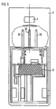
- Figur 3 eine Draufsicht auf einen unverschlossenen Stiftstecker,
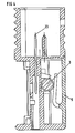
- Figur 4 eine geschnittene Seitenansicht des Stiftsteckers nach Figur 3,
- Figur 5 eine Draufsicht auf eine weitere Ausführung eines erfindungsgemäßen Stiftsteckers,
- Figur 6 eine Ansicht der im erfindungsgemäßen Steckverbinders verwendbaren Kurzschlußbrücke.
- Der in Figur 1 dargestellte Steckverbinder besteht aus einem Stiftstecker 1 und einem Buchsenstecker 8, 9 und 15. In den annähernd zylindrischen Stiftstecker 1 sind in Axialrichtung Stiftkontakte, beispielsweise mit einem Querschnitt von 0,63 x 0,63 mm und mit einer vergoldeten Kontaktoberfläche, eingepreßt. Von den äußeren Abmessungen her ist die Stiftsteckerausführung als sechspolige, zweireihige Kontaktanordnung mit stirnseitigem Kabelabgang ausgeführt. Die buchsenseitige Stirnseite des Stiftsteckers 1 ist offen, so daß der Stiftstecker 1 dort zur teilweisen Aufnahme des Buchsensteckers bei der Kupplung ausgebildet ist. Die Kupplung wird durch an sich bekannte Führungs- und Rastmittel, insbesondere einen federnden Rasthaken 13 am Buchsenstecker und eine passende Rastöffnung 4 am Stiftstecker 1, unterstützt. Eine vorteilhafte Fixiermöglichkeit des Steckverbinders beispielsweise am Fahrzeugchassis ist durch den dargestellten integrierten Schnapphaken 2 gegeben.
- Der Stiftstecker 1 weist zur kabelabgangsseitigen Stirnseite hin zwei durch einen ersten und zweiten Verschlußdeckel 5 und 6 verschließbare, annähernd als Halbzylinder ausgebildete Kammern auf, die für die getrennte Aufnahme des Filter-Bauelementes bzw. der Buchsenkontakte 11 vorgesehen sind. Durch diese Anordnung sind gute Zugangs- und Verriegelungsmöglichkeiten gewährleistet. Als Filter-Bauelement kann vorzugsweise eine in Reihe geschaltete, als Tiefpaß dienende Spule 3 eingesetzt werden. Es kann jedoch auch ein anderes Bauelement, beispielsweise ein Kondensator oder ein Draht, angeschlossen werden. Die Spule 3 kann, wie in den Figuren 3 bis 5 dargestellt, quer oder parallel zur Axialrichtung des Stiftsteckers 1 angeordnet werden. Sie kann im übrigen auch ohne weiteres mit Kunststoff umgossen werden.
- Damit einerseits Spulen mit den üblichen Maßtoleranzen verwendet werden können, die andererseits aber durch die im Betrieb auftretenden hohen Beschleunigungen (10 G und mehr), die auf Vibrationen zurückgehen, nicht beschädigt werden, ist es vorteilhaft, wenn die durch den ersten Verschlußdeckel 5 verschließbare erste Kammer eine zur Aufnahme des etwas kleineren Bauelementes bestimmte wannenartige Ausformung aufweist, in der das Bauelement durch mindestens einen, in Figur 4 dargestellten, an der Innenseite des ersten Verschlußdeckels 5 angeformten Federlappen federnd gehalten ist. Der mit Torsionsrasthaken versehene erste Verschlußdeckel 5 drückt die Spule 3, nach dem Aufsetzen und Verrasten am Stiftstecker 1, in die Aufnahme. Der erste Verschlußdeckel 5 kann ohne Gewaltanwendung nicht wieder demontiert werden. Durch das Andrücken der Spule durch den Federlappen werden Vibrationen ausreichend gedämpft.
- Die sich in der in Figur 1 gewählten Darstellung nicht einsehbar nach unten hin öffnende zweite Kammer des Stiftsteckers 1 dient vornehmlich zur Aufnahme der Buchsenkontakte 11, für die in ihrer Basis Aufnahmen zum Einstecken und Fenster zum primären Sichern der vorzugsweise als Rasthülse mit Federlappen ausgebildeten Buchsenkontakte 11. Die aus Sicherheitsgründen vorgeschriebene Sekundärverriegelung kann vorteilhafterweise durch einen an der Innenseite des die zweite Kammer verschließenden zweiten Verschlußdeckels 6 angeformten Quersteg 7 erfolgen, durch den die Buchsenkontakte 11 des Stiftsteckers 1 bei geschlossenem Verschlußdeckel 6 endgültig gesichert sind. Zum Verschließen wird der zweite Verschlußdeckel 6 seitlich am Stiftstecker 1 in Scharniere eingelegt und eingeschwenkt. Er rastet über einen am Stiftstecker 1 angespritzten Rasthaken ein, kann aber, der leichteren Zugänglichkeit wegen, wieder geöffnet werden.
- Der Buchsenstecker besteht, wie in Figur 1 dargestellt, aus einem in eine Abdeckkappe 8 polarisiert einschiebbaren Buchsengehäuse 9, in dem die Buchsenkontakte 10 und die mindestens eine, in Figur 6 detaillierter dargestellte Kurzschlußbrücke 12 angeordnet sind, und aus einer axial auf die Abdeckkappe 8 aufschiebbaren Verschlußplatte 15. Dabei ist das Buchsengehäuse 9 mit Führungsnuten 16 versehen, in die beim Einschieben in die Abdeckkappe 8 an dieser angeformte Führungsrippen 14 eingreifen, wobei gleichzeitig eine endgültige Sicherung der Buchsenkontakte 10 bewirkt ist. Auf der Abdeckkappe 8 sind darüber hinaus Rastnasen und an der Verschlußplatte 15 entsprechende Vertiefungen vorgesehen, wobei ein falsches Aufschieben durch eine geschlossene Nut an der Abdeckkappe 8 vermieden wird.
- In Figur 2 ist eine erfindungsgemäße Verschaltung der Kontaktstifte 21, 22 und 23 mit der Filter-Spule dargestellt. Es ist erkennbar, daß das Filter-Bauelement mit den abgewinkelten Enden zweier Kontaktstiftteile 21 elektrisch verbunden ist, die, um 180° gedreht und gespiegelt, seitlich versetzt zueinander in einer Reihe mit den anderen Kontaktstiften im Stiftstecker angeordnet und befestigt sind. Diese Realisierung der Reihenschaltung ist, über den grundsätzlichen Vorteil jeder erfindungsgemäßen Ausführung, eine in einem einzigen Steckverbinder mit Kurzschlußelement integrierte Reihenschaltung vorzusehen hinaus, dadurch vorteilhaft, daß zwei identische Kontaktstiftteile, die jedoch unsymmetrisch montiert werden, verwendet werden können, was insbesondere einen leichten Einbau in zwei identischen Arbeitsgängen ermöglicht. Üblicherweise ist einer der im Buchsenstecker kurzgeschlossenen Kontaktwege mit der Reihenschaltung versehen. Die beiden übrigen Kontaktstifte 22 und 23, von denen einer im dargestellten Ausführungsbeispiel weder als Stromversorgungs- noch Masseanschluß, sondern als eine fakultative Anschlußmöglichkeit dient, sind mit ihren beiden Enden jeweils unmittelbar in die axial in einer Linie liegenden Buchsenkontakte des Stiftsteckers und des Buchsensteckers eingesteckt, während die durch die beiden Kontaktstiftteile 21 und die in Reihe geschaltete Spule miteinander verbundenen Buchsenkontakte seitlich etwas versetzt sind, was den Spielraum für die Anordnung der Spule oder eines anderen Filter-Bauelementes erheblich erhöht.
Claims (8)
- Steckverbinder-Kupplung, mit einem Buchsenstecker (8, 9, 15) und mit einem Stiftstecker (1), die zusammen ein Stecker-Pärchen bilden und die aus Isoliermaterial bestehen und jeweils Aufnahmen zum Einstecken und primärem Sichern von Buchsenkontakten aufweisen, wobei mindestens eine federnde Kurzschlußbrücke (12) vorgesehen ist, die jeweils zwei Buchsenkontakte des Buchsensteckers miteinander verbindet, und wobei der Stiftstecker, parallel zu in mindestens einer Reihe angeordneten Kontaktstiften, die zum Einstecken in die entsprechend angeordneten Buchsenkontakte des Buchsensteckers bestimmt und jeweils mit den eigenen Buchsenkontakten verbunden sind, für jede Kurzschlußbrücke ein Unterbrecherelement aufweist, welches bei der Kupplung von Buchsenstecker und Stiftstecker den Kurzschluß zwischen den jeweils zwei Buchsenkontakten aufhebt, dadurch gekennzeichnet, daß im Stiftstecker (1) ein elektrisches Filter-Bauelement integriert und in Reihe zwischen zwei bei der Kupplung miteinander verbundenen Buchsenkontakten (10, 11) des Stecker-Pärchens geschaltet ist.
- Steckverbinder nach Anspruch 1, dadurch gekennzeichnet, daß das Bauelement mit den abgewinkelten Enden zweier Kontaktstiftteile (21) elektrisch verbunden ist, die, um 180° gedreht und gespiegelt, seitlich versetzt zueinander in einer Reihe mit den anderen Kontaktstiften (22, 23) im Stiftstecker (1) angeordnet und befestigt sind.
- Steckverbinder nach Anspruch 1 oder 2, dadurch gekennzeichnet, daß der Stiftstecker (1) annähernd zylindrisch ausgebildet ist, wobei die buchsenseitige Stirnseite offen ist und der Stiftstecker (1) dort zur teilweisen Aufnahme des Buchsensteckers bei der Kupplung ausgebildet ist, und wobei der Stiftstecker (1) zur kabelabgangsseitigen Stirnseite hin zwei durch einen ersten und zweiten Verschlußdeckel (5, 6) verschließbare, insbesondere annähernd als Halbzylinder ausgebildete Kammern aufweist, die für die getrennte Aufnahme des Bauelementes bzw. der Buchsenkontakte (11) vorgesehen sind.
- Steckverbinder nach Anspruch 3, dadurch gekennzeichnet, daß die durch den ersten Verschlußdeckel (5) verschließbare erste Kammer eine zur Aufnahme des etwas kleineren Bauelementes bestimmte wannenartige Ausformung aufweist, in der das Bauelement durch mindestens einen an der Innenseite des ersten Verschlußdeckels (5) angeformten Federlappen federnd gehalten ist.
- Steckverbinder nach einem der Ansprüche 1 bis 4, dadurch gekennzeichnet, daß der Buchsenstecker aus einem in eine Abdeckkappe (8) polarisiert einschiebbaren Buchsengehäuse (9), in dem die Buchsenkontakte (10) und die mindestens eine Kurzschlußbrücke (12) angeordnet sind, und aus einer axial auf die Abdeckkappe (8) aufschiebbaren Verschlußplatte (15) besteht.
- Steckverbinder nach Anspruch 5, dadurch gekennzeichnet, daß das Buchsengehäuse (9) mit Führungsnuten (16) versehen ist, in die beim Einschieben in die Abdeckkappe (8) an dieser angeformte Führungsrippen (14) eingreifen, wobei gleichzeitig eine endgültige Sicherung der Buchsenkontakte (10) bewirkt ist.
- Steckverbinder nach einem der Ansprüche 3 bis 6, dadurch gekennzeichnet, daß die Buchsenkontakte (11) des Stiftsteckers (1) durch einen an der Innenseite des die zweite Kammer verschließenden zweiten Verschlußdeckels (6) angeformten Quersteg (7) endgültig gesichert sind.
- Steckverbinder nach einem der Ansprüche 1 bis 7, dadurch gekennzeichnet, daß im Stiftstecker (1) eine Spule (3) als Filter-Bauelement integriert ist.
Applications Claiming Priority (2)
| Application Number | Priority Date | Filing Date | Title |
|---|---|---|---|
| DE9314667U DE9314667U1 (de) | 1993-09-28 | 1993-09-28 | Steckverbinder-Kupplung |
| DE9314667U | 1993-09-28 |
Publications (2)
| Publication Number | Publication Date |
|---|---|
| EP0647988A1 EP0647988A1 (de) | 1995-04-12 |
| EP0647988B1 true EP0647988B1 (de) | 1996-12-11 |
Family
ID=6898666
Family Applications (1)
| Application Number | Title | Priority Date | Filing Date |
|---|---|---|---|
| EP94114145A Expired - Lifetime EP0647988B1 (de) | 1993-09-28 | 1994-09-08 | Steckverbinder-Kupplung |
Country Status (6)
| Country | Link |
|---|---|
| US (1) | US5580260A (de) |
| EP (1) | EP0647988B1 (de) |
| JP (1) | JPH07169534A (de) |
| KR (1) | KR100313470B1 (de) |
| DE (2) | DE9314667U1 (de) |
| ES (1) | ES2095120T3 (de) |
Families Citing this family (8)
| Publication number | Priority date | Publication date | Assignee | Title |
|---|---|---|---|---|
| US5999400A (en) * | 1998-11-30 | 1999-12-07 | Berg Technology, Inc. | Modular plug with electronic components |
| TW490892B (en) * | 2000-02-04 | 2002-06-11 | Sony Computer Entertainment Inc | Connector and method of making |
| JP2002319459A (ja) * | 2001-04-20 | 2002-10-31 | Jst Mfg Co Ltd | スクイブ用コネクタおよびその部品 |
| USD475684S1 (en) | 2002-07-08 | 2003-06-10 | Aten International Co., Ltd | Main body of an automatic switch |
| JP4246131B2 (ja) * | 2004-10-04 | 2009-04-02 | 矢崎総業株式会社 | 電線と素子内蔵ユニットとの接続構造 |
| JP4379823B2 (ja) * | 2007-09-25 | 2009-12-09 | 株式会社デンソー | 車両の充電システム |
| ITUB20159751A1 (it) * | 2015-12-30 | 2017-06-30 | Johnson Electric Asti S R L | Cablaggio con connettore integrato, particolarmente per autoveicoli. |
| CN108442924B (zh) * | 2018-04-25 | 2023-06-09 | 山东科技大学 | 一种钻孔原位探测推进装置及其使用方法 |
Family Cites Families (12)
| Publication number | Priority date | Publication date | Assignee | Title |
|---|---|---|---|---|
| US4113340A (en) * | 1977-06-27 | 1978-09-12 | Illinois Tool Works Inc. | Protective electrical device |
| US4113341A (en) * | 1977-08-12 | 1978-09-12 | Amp Incorporated | Electrical connector having provision for circuit components |
| DE8531990U1 (de) * | 1985-11-13 | 1986-01-16 | C.A. Weidmüller GmbH & Co, 4930 Detmold | Elektrischer Doppelsteckverbinder mit Kurzschlußbrücke |
| US4786258A (en) * | 1987-05-13 | 1988-11-22 | Amp Incorporated | Electrical connector with shunt |
| US5139442A (en) * | 1990-12-03 | 1992-08-18 | Murata Manufacturing Co., Ltd. | Modular jack |
| US5108300A (en) * | 1991-04-16 | 1992-04-28 | Amp Incorporated | Electrical connector with interlocked components |
| DE9112178U1 (de) * | 1991-09-30 | 1992-07-16 | Siemens AG, 8000 München | Steckverbinder mit Kurzschlußbrücke |
| DE9112718U1 (de) * | 1991-10-12 | 1991-11-28 | Alape Adolf Lamprecht Kg, 3380 Goslar | Spül- oder Ausgußbecken |
| DE4217205C2 (de) * | 1992-05-23 | 1994-09-08 | Amphenol Tuchel Elect | Steckverbinder |
| GB9225118D0 (en) * | 1992-12-01 | 1993-01-20 | Amp Gmbh | Shunted airbag connector |
| US5340325A (en) * | 1993-08-26 | 1994-08-23 | Pai Tien Fa | Capacitive coupled BNC type self-terminating coaxial connector |
| US5382173A (en) * | 1993-09-01 | 1995-01-17 | Trompeter Electronics, Inc. | Electrical connector |
-
1993
- 1993-09-28 DE DE9314667U patent/DE9314667U1/de not_active Expired - Lifetime
-
1994
- 1994-09-08 EP EP94114145A patent/EP0647988B1/de not_active Expired - Lifetime
- 1994-09-08 ES ES94114145T patent/ES2095120T3/es not_active Expired - Lifetime
- 1994-09-08 DE DE59401259T patent/DE59401259D1/de not_active Expired - Fee Related
- 1994-09-26 JP JP6256261A patent/JPH07169534A/ja active Pending
- 1994-09-27 KR KR1019940024270A patent/KR100313470B1/ko not_active Expired - Fee Related
- 1994-09-28 US US08/313,862 patent/US5580260A/en not_active Expired - Fee Related
Also Published As
| Publication number | Publication date |
|---|---|
| US5580260A (en) | 1996-12-03 |
| KR100313470B1 (ko) | 2002-02-19 |
| ES2095120T3 (es) | 1997-02-01 |
| DE9314667U1 (de) | 1994-03-17 |
| DE59401259D1 (de) | 1997-01-23 |
| EP0647988A1 (de) | 1995-04-12 |
| KR950010186A (ko) | 1995-04-26 |
| JPH07169534A (ja) | 1995-07-04 |
Similar Documents
| Publication | Publication Date | Title |
|---|---|---|
| EP2156524B1 (de) | Leistungstrennschalter für ein kraftfahrzeug | |
| DE69521580T2 (de) | Elektrischer Verbinder mit Kontaktlagesicherungsvorrichtung welche das vollständige Einsetzen der Kontakte erleichtert | |
| DE19500959C2 (de) | Elektrischer Steckverbinder | |
| DE69205946T2 (de) | Abgeschirmter schwimmender elektrischer Verbinder. | |
| DE4311767A1 (de) | Elektrische Verbinderanordnung | |
| DE69412696T2 (de) | Verbinder mit selektiv aufhebbarem Kurzschluss der Anschlüsse | |
| DE3909912A1 (de) | Vielpolige steckvorrichtung | |
| DE69604884T2 (de) | Elektrische Verbindereinrichtung | |
| EP0647988A1 (de) | Steckverbinder-Kupplung | |
| DE10202920B4 (de) | Elektrische Steckverbindung | |
| EP2156523B1 (de) | Leistungstrennschalter für ein kraftfahrzeug | |
| DE69415786T2 (de) | Verbinder mit Verriegelungserkennung | |
| EP1139493A2 (de) | Elektrischer Verbinder zum Anschluss von elektrischen Leitern an ein elektrisches Gerät | |
| EP1411596B1 (de) | Stecker mit Halteelement | |
| DE19840648C1 (de) | Elektrischer Steckverbinder | |
| DE112009001573B4 (de) | Hochvolt-Steckverbindung sowie Verwendung einer solchen | |
| EP3504760B1 (de) | Mehrfachkontaktstecker mit integriertem kurzschlussbrückenelement | |
| DE20216337U1 (de) | Steckverbinder zur Verbindung mit einem Zünder eines Airbagmoduls mit integriertem Massekontakt | |
| DE10127504B4 (de) | Aufnahmeeinrichtung für eine elektrische Komponente mit wenigstens einer Steckeraufnahme | |
| DE19828968A1 (de) | Elektrischer Steckverbinder | |
| EP1045661A1 (de) | Staubsauger | |
| DE102004037277B4 (de) | Elektrischer Mehrfachstecker | |
| DE19747115A1 (de) | Elektrische Steckverbinderanordnung und elektrischer Kontakt | |
| DE102005016024A1 (de) | Elektrische Verbindungsanordnung für Zünder | |
| EP1720222A2 (de) | Steckverbinder, insbesondere für Airbag-Zündsysteme |
Legal Events
| Date | Code | Title | Description |
|---|---|---|---|
| PUAI | Public reference made under article 153(3) epc to a published international application that has entered the european phase |
Free format text: ORIGINAL CODE: 0009012 |
|
| AK | Designated contracting states |
Kind code of ref document: A1 Designated state(s): BE DE ES FR GB IT SE |
|
| 17P | Request for examination filed |
Effective date: 19950504 |
|
| 17Q | First examination report despatched |
Effective date: 19951110 |
|
| GRAH | Despatch of communication of intention to grant a patent |
Free format text: ORIGINAL CODE: EPIDOS IGRA |
|
| GRAH | Despatch of communication of intention to grant a patent |
Free format text: ORIGINAL CODE: EPIDOS IGRA |
|
| GRAA | (expected) grant |
Free format text: ORIGINAL CODE: 0009210 |
|
| AK | Designated contracting states |
Kind code of ref document: B1 Designated state(s): BE DE ES FR GB IT SE |
|
| REF | Corresponds to: |
Ref document number: 59401259 Country of ref document: DE Date of ref document: 19970123 |
|
| REG | Reference to a national code |
Ref country code: ES Ref legal event code: FG2A Ref document number: 2095120 Country of ref document: ES Kind code of ref document: T3 |
|
| ITF | It: translation for a ep patent filed | ||
| GBT | Gb: translation of ep patent filed (gb section 77(6)(a)/1977) |
Effective date: 19970214 |
|
| ET | Fr: translation filed | ||
| PLBE | No opposition filed within time limit |
Free format text: ORIGINAL CODE: 0009261 |
|
| STAA | Information on the status of an ep patent application or granted ep patent |
Free format text: STATUS: NO OPPOSITION FILED WITHIN TIME LIMIT |
|
| 26N | No opposition filed | ||
| PGFP | Annual fee paid to national office [announced via postgrant information from national office to epo] |
Ref country code: SE Payment date: 20000901 Year of fee payment: 7 |
|
| PGFP | Annual fee paid to national office [announced via postgrant information from national office to epo] |
Ref country code: ES Payment date: 20000926 Year of fee payment: 7 |
|
| PGFP | Annual fee paid to national office [announced via postgrant information from national office to epo] |
Ref country code: BE Payment date: 20001010 Year of fee payment: 7 |
|
| REG | Reference to a national code |
Ref country code: GB Ref legal event code: 732E |
|
| PG25 | Lapsed in a contracting state [announced via postgrant information from national office to epo] |
Ref country code: SE Free format text: LAPSE BECAUSE OF NON-PAYMENT OF DUE FEES Effective date: 20010909 Ref country code: ES Free format text: LAPSE BECAUSE OF NON-PAYMENT OF DUE FEES Effective date: 20010909 |
|
| PG25 | Lapsed in a contracting state [announced via postgrant information from national office to epo] |
Ref country code: BE Free format text: LAPSE BECAUSE OF NON-PAYMENT OF DUE FEES Effective date: 20010930 |
|
| REG | Reference to a national code |
Ref country code: GB Ref legal event code: IF02 |
|
| BERE | Be: lapsed |
Owner name: SIEMENS A.G. Effective date: 20010930 |
|
| EUG | Se: european patent has lapsed |
Ref document number: 94114145.9 |
|
| PGFP | Annual fee paid to national office [announced via postgrant information from national office to epo] |
Ref country code: GB Payment date: 20020808 Year of fee payment: 9 |
|
| PGFP | Annual fee paid to national office [announced via postgrant information from national office to epo] |
Ref country code: FR Payment date: 20020903 Year of fee payment: 9 |
|
| PGFP | Annual fee paid to national office [announced via postgrant information from national office to epo] |
Ref country code: DE Payment date: 20020930 Year of fee payment: 9 |
|
| PG25 | Lapsed in a contracting state [announced via postgrant information from national office to epo] |
Ref country code: GB Free format text: LAPSE BECAUSE OF NON-PAYMENT OF DUE FEES Effective date: 20030908 |
|
| PG25 | Lapsed in a contracting state [announced via postgrant information from national office to epo] |
Ref country code: DE Free format text: LAPSE BECAUSE OF NON-PAYMENT OF DUE FEES Effective date: 20040401 |
|
| GBPC | Gb: european patent ceased through non-payment of renewal fee |
Effective date: 20030908 |
|
| REG | Reference to a national code |
Ref country code: ES Ref legal event code: FD2A Effective date: 20021011 |
|
| PG25 | Lapsed in a contracting state [announced via postgrant information from national office to epo] |
Ref country code: FR Free format text: LAPSE BECAUSE OF NON-PAYMENT OF DUE FEES Effective date: 20040528 |
|
| REG | Reference to a national code |
Ref country code: FR Ref legal event code: ST |
|
| PG25 | Lapsed in a contracting state [announced via postgrant information from national office to epo] |
Ref country code: IT Free format text: LAPSE BECAUSE OF NON-PAYMENT OF DUE FEES;WARNING: LAPSES OF ITALIAN PATENTS WITH EFFECTIVE DATE BEFORE 2007 MAY HAVE OCCURRED AT ANY TIME BEFORE 2007. THE CORRECT EFFECTIVE DATE MAY BE DIFFERENT FROM THE ONE RECORDED. Effective date: 20050908 |