EP0647961A1 - Device for coating elongated bendable products - Google Patents
Device for coating elongated bendable products Download PDFInfo
- Publication number
- EP0647961A1 EP0647961A1 EP94114602A EP94114602A EP0647961A1 EP 0647961 A1 EP0647961 A1 EP 0647961A1 EP 94114602 A EP94114602 A EP 94114602A EP 94114602 A EP94114602 A EP 94114602A EP 0647961 A1 EP0647961 A1 EP 0647961A1
- Authority
- EP
- European Patent Office
- Prior art keywords
- long
- cathode
- elongated flexible
- electrode blocks
- cathodes
- Prior art date
- Legal status (The legal status is an assumption and is not a legal conclusion. Google has not performed a legal analysis and makes no representation as to the accuracy of the status listed.)
- Ceased
Links
Images

Classifications
-
- H—ELECTRICITY
- H01—ELECTRIC ELEMENTS
- H01J—ELECTRIC DISCHARGE TUBES OR DISCHARGE LAMPS
- H01J37/00—Discharge tubes with provision for introducing objects or material to be exposed to the discharge, e.g. for the purpose of examination or processing thereof
- H01J37/32—Gas-filled discharge tubes
- H01J37/32431—Constructional details of the reactor
- H01J37/32733—Means for moving the material to be treated
- H01J37/32752—Means for moving the material to be treated for moving the material across the discharge
- H01J37/32761—Continuous moving
- H01J37/3277—Continuous moving of continuous material
-
- C—CHEMISTRY; METALLURGY
- C23—COATING METALLIC MATERIAL; COATING MATERIAL WITH METALLIC MATERIAL; CHEMICAL SURFACE TREATMENT; DIFFUSION TREATMENT OF METALLIC MATERIAL; COATING BY VACUUM EVAPORATION, BY SPUTTERING, BY ION IMPLANTATION OR BY CHEMICAL VAPOUR DEPOSITION, IN GENERAL; INHIBITING CORROSION OF METALLIC MATERIAL OR INCRUSTATION IN GENERAL
- C23C—COATING METALLIC MATERIAL; COATING MATERIAL WITH METALLIC MATERIAL; SURFACE TREATMENT OF METALLIC MATERIAL BY DIFFUSION INTO THE SURFACE, BY CHEMICAL CONVERSION OR SUBSTITUTION; COATING BY VACUUM EVAPORATION, BY SPUTTERING, BY ION IMPLANTATION OR BY CHEMICAL VAPOUR DEPOSITION, IN GENERAL
- C23C14/00—Coating by vacuum evaporation, by sputtering or by ion implantation of the coating forming material
- C23C14/22—Coating by vacuum evaporation, by sputtering or by ion implantation of the coating forming material characterised by the process of coating
- C23C14/56—Apparatus specially adapted for continuous coating; Arrangements for maintaining the vacuum, e.g. vacuum locks
- C23C14/562—Apparatus specially adapted for continuous coating; Arrangements for maintaining the vacuum, e.g. vacuum locks for coating elongated substrates
-
- H—ELECTRICITY
- H01—ELECTRIC ELEMENTS
- H01J—ELECTRIC DISCHARGE TUBES OR DISCHARGE LAMPS
- H01J37/00—Discharge tubes with provision for introducing objects or material to be exposed to the discharge, e.g. for the purpose of examination or processing thereof
- H01J37/32—Gas-filled discharge tubes
- H01J37/34—Gas-filled discharge tubes operating with cathodic sputtering
- H01J37/3402—Gas-filled discharge tubes operating with cathodic sputtering using supplementary magnetic fields
-
- H—ELECTRICITY
- H01—ELECTRIC ELEMENTS
- H01J—ELECTRIC DISCHARGE TUBES OR DISCHARGE LAMPS
- H01J37/00—Discharge tubes with provision for introducing objects or material to be exposed to the discharge, e.g. for the purpose of examination or processing thereof
- H01J37/32—Gas-filled discharge tubes
- H01J37/34—Gas-filled discharge tubes operating with cathodic sputtering
- H01J37/3411—Constructional aspects of the reactor
- H01J37/3414—Targets
- H01J37/342—Hollow targets
Definitions
- the invention relates to the fields of metallurgy, the cable industry and device construction and relates to an apparatus for coating elongated flexible products, such as e.g. Wires, fibers, threads, by means of cathode sputtering in a gas atmosphere at low pressure, which e.g. as special wires or as wire ropes with improved quality.
- elongated flexible products such as e.g. Wires, fibers, threads
- a device for applying a metal coating to metal products by means of the continuous application of the fine powder coating material to the surface of the horizontally moving steel strip (US 2812270).
- This device consists of two vacuum chambers. One vacuum chamber is used to apply the coating material and the other to heat the steel strip. With the help of a transport device with unwinding and unwinding devices, the steel strip is through them Vacuum chambers drawn, with an aluminum coating is applied. The steel strip moves horizontally at least in the area of the coating.
- this device is only used to apply a metal coating to steel strips. When using this device for coating wire, fibers or threads, large losses of atomizing material would occur because of the small cross sections. There are also restrictions on the atomizing materials used.
- the device for coating wire with fusible metal (US 4357365) with continuous passage of wire in the vertical direction to the chamber axis is known. It consists of a coating chamber with inlet and outlet openings for the gas mixture, a transport system with unwinding and winding devices for wire transport and a current source connected to the contacts of the coating chamber for heating the wire.
- a device has a limited area of application since it is not suitable for coating non-electrically conductive threads or fibers.
- the gas phase method for coating wire has a lower performance compared to the vacuum deposition method.
- the devices for coating by means of vacuum deposition include the magnetron sputtering device (PCT 092/01082), which consists of an electrode block with a hollow cylindrical long cathode and anodes arranged in the vicinity thereof. The inside surface of the cathode is covered with the atomizing material.
- the device contains built-in magnets that encircle the hollow long cathode.
- the sputtering is carried out on the horizontally moving carrier, which is located outside the inner cavity of the cathode, through an opening in the cathode wall.
- Such devices have the advantage that the losses of the cathode material are reduced and the cathode sputtering is carried out more evenly by the use of magnets.
- the disadvantage of this device is that it is used to coat flat substrate material which, because of its size, cannot be arranged in the cathode, which reduces the dusting rate and the performance of the device.
- magnetron devices for coating substrates are known (US 4960753).
- This magnetron device consists of several individual devices which are arranged one above the other. In each individual device, the continuous substrate is coated with different materials.
- One of these devices consists of a cylindrical anode, a cylindrical cathode which is arranged around the anode with a larger diameter, and a device for producing it of a magnetic field, which is also arranged with a larger diameter around the cathode.
- the anode is in principle internal with respect to the longitudinal axis of the cylinder arrangement. This arrangement is typical of a magnetron.
- the disadvantage of this device is that the anode is exposed to the coating material and that only a circular magnetic field can be generated by the magnetic field thus arranged.
- an electrode charging device for material atomization and deposition on elongated flexible products (for example on wire) which are conveyed horizontally in the gas atmosphere at a pressure of less than or equal to 13.2 Pa (US 3884793).
- This device contains an electrode block which consists of a hollow long cylinder cathode between two cylinder anodes installed coaxially thereto and of the insulating elements arranged between the cathode and the anodes. The inside surface of the cathode is covered with the atomizing material.
- the device also contains magnets for generating magnetic fields in the cathode, which act parallel to the longitudinal axis of the cathode. The magnets enclose the electrode block and are designed as permanently installed magnetic coils on ferromagnetic plates.
- the inner cavity of the cathode communicates with the inner cavity of the vacuum chamber into which the transport system for the transport of the products to be coated, including the Unwinding and winding devices installed.
- Gas supply devices and a current source connected to the electrode block are provided in the device.
- a disadvantage of this device is low power because the wire is pulled horizontally and it is impossible to secure the desired thickness of the cover layer in one pass through the cathode.
- the cathode material wears out unevenly since the distance from the center of the cathode is greater than the distance between the cathode and each anode.
- This device also has a short lifespan because there is no protective device against the undesired coating of the insulating elements arranged between the cathode and the anodes.
- the invention has for its object to provide a device for coating elongated flexible products by means of cathode sputtering, in which products to be drawn vertically can be coated with a uniform layer thickness, with low evaporation material losses and high throughput.
- the device according to the invention for coating elongated flexible products contains electrode blocks which consist of hollow cylindrical long cathodes and cylinder anodes attached to the end faces of the long cathodes and insulating elements arranged therebetween with a common central axis, the long cathodes being coated on their inner surface with target materials or entirely from the same Target material exist.
- electrode blocks which consist of hollow cylindrical long cathodes and cylinder anodes attached to the end faces of the long cathodes and insulating elements arranged therebetween with a common central axis, the long cathodes being coated on their inner surface with target materials or entirely from the same Target material exist.
- at least two electrode blocks are arranged vertically one above the other.
- the device also contains arrangements for generating a magnetic field, which enclose the hollow cylindrical long cathodes. According to the invention, these arrangements are arranged around the hollow cylindrical long cathodes so as to be rotatable and displaceable along the long cathode axis.
- the device also contains systems for transporting and winding and unwinding the elongated flexible products.
- vacuum chambers which accommodate at least the long cathodes and the systems for transporting the elongated, flexible products, which can be accommodated in a common or in separate vacuum chambers.
- the device further contains electrically insulating screens which are arranged between the long cathodes and the cylinder anodes on the insulating elements, the inside diameter of the screens being larger than the inside diameter of the long cathode and smaller than the diameter of the interior cavities of the cylinder anode.
- At least two electrode blocks arranged vertically one above the other are advantageously arranged in parallel next to one another.
- the gas supply is also advantageously located between the systems for winding and unwinding the elongated flexible products, the direction of gas flow being directed against the direction of movement of the elongated flexible products.
- the screens can be dismantled.
- the vertical structure of the device enables the elongated flexible products to be of uniform layer thickness, with low target material losses and with a high level Throughput can be coated. It is necessary to transport the products exactly vertically or in a region along the cathode axis and symmetrical to it with a radius that is 0.2 from the cathode radius, since the uniformity of the coating of products depends on this. If the deviation from the vertical when moving products exceeds the specified value, problems arise when transporting the products. Due to the sag, the evaporation evenness drops and additional loads arise in the transport system because additional forces have to be applied to clamp the products.
- the arrangement in the device for generating the magnetic field consists of plates comprising the cathode, made of a material with high magnetic permeability, with permanent magnets arranged in between, which have an alternating polarity.
- the plates which are magnetized with the help of permanent magnets, serve this purpose.
- the arrangement for generating the magnetic field is moved along the longitudinal axis of the long cathode and around this axis in order to achieve the uniform coating of products and the uniform atomization of the target material.
- the electrode blocks in the device can be arranged in a vertical line, one after the other. This arrangement has particular advantages if thin products and products with low mechanical strength are to be steamed with them. This ensures a tear-free feed during vapor deposition in the transport system.
- the device according to the invention also contains electrically insulated screens with cylindrical inner cavities, which are installed in the electrode block between the long cathode and the cylinder anodes. This is necessary to ensure a stable discharge and the reproducibility of the coating, since the parameters of the discharge depend on the geometry of the inner surfaces of the long cathode, the cylinder anodes and the electrically insulated screens depend on which are crucial for dusting on the products.
- the inside diameter of the electrically insulated screens is larger than the inside diameter of the long cathode and smaller than the inside diameter of the cylinder anodes. This is necessary to secure the insulating elements against fogging by the cathode material, since the service life of the device also depends to a large extent on this undesirable fogging of the insulating elements.
- the long cathode, cylinder anodes and electrically insulated shields can be dismantled and the inner diameter is smaller than the diameter of the insulating elements.
- the arrangement of the gas supply device between the systems for winding and unwinding the elongated flexible products ensures the increase in the top layer quality and at the same time the protection of the system for transporting and winding and unwinding the elongated flexible products against fogging by the choice of the guidance of the gas mixture from the Gas supply device through the inner cavities of the long cathodes into the vacuum chambers.
- the quality of the cover layer increases with the reduction in the amount of foreign substances which, as a result of the countercurrent, cannot penetrate into the inner cavities of the long cathodes during evaporation from the systems for transporting, winding and unwinding the elongated flexible products.
- two electrode blocks arranged vertically one above the other are made parallel arranged to each other.
- the device for coating elongated flexible products works as follows.
- the elongated flexible products to be coated are placed on the system for transporting and winding and unwinding the elongated flexible products.
- the vacuum chambers are then evacuated.
- the gas supply is then heated. After the desired temperature has been reached, the gas supply is opened and the gas mixture enters the inner cavity of the long cathode.
- the uniform supply is controlled by the temperature control of the gas supply e.g. secured with the help of a thermal resistor. With the help of the power source, a potential is generated on the surface of the long cathode and the electrical discharge in the long cathode is maintained in the specified capacity range (e.g. 1000 W).
- the cylinder anodes are separated from the long cathode by the electrically insulated screens.
- the electrical insulation elements also serve as a vacuum seal.
- the arrangement for generating the magnetic field with the plates and the permanent magnet moves relative to the long cathode during coating.
- a closed cover layer is formed from the target material on the products to be coated, with a high degree of homogeneity with regard to the length and circumference of the product.
- the pressure of the gas mixture is maintained in the range 10-0.01 mm Hg, the speed of the gas phase generation from the material of the long cathode and the constancy of the coating parameters of the device increase.
- the products are transported along the cathode axis in the vertical direction at a speed of 0.01 - 10 m / min.
- This speed range was chosen for the following reasons: At a speed of less than 0.1 m / min, the products heat up significantly, which often results in breaks; moreover, the device is not very effective at such speeds. When transporting above 20 m / min, it is difficult to master the natural vibrations of the products and to achieve acceptable minimum layer thicknesses.
- An improvement in the top layer quality and an increase in the coating rate can be achieved in this device by supplying a gas mixture into the cavity of the long cathode.
- a gas mixture For example, when adding an argon-xenon mixture, the coating rate increases.
- ammonia to the Gas mixing results in both an increase in the coating rate and an improvement in the layer quality.
- the addition of helium improves the quality due to the reduction in porosity.
- the working gas After exiting the vacuum chamber, the working gas is collected and fed again into the inner cavity of the long cathode.
- the purity of the target material is of great importance because of the material transfer to the products. Since gas separation also takes place during material transfer, the purity of the gas to be used is very important. Even small admixtures of active gases, e.g. of oxygen and nitrogen, have a major influence on the chemical composition of the cover layers when multiple target material transfer.
- active gases e.g. of oxygen and nitrogen
- the gas is cleaned of reactive admixtures as a result of their adsorption with the target material which is transferred during the coating. It is advisable to reuse such a cleaned gas for work. In addition, the saving of such expensive gases as helium, krypton and xenon is a not insignificant economic factor.
- the gas mixture can contain inert and reactive gases. This enables different types of insulating, wear-resistant or to produce decorative cover layers.
- oxygen it is possible, for example, to produce insulating or wear-resistant cover layers based on oxides, because when using an aluminum cathode, the cover layers produced have good insulating properties and good wear resistance;
- nitrogen as a reactive gas
- decorative cover layers can be made from titanium nitride, etc.
- New treatment principles are possible when coating electrically conductive parts.
- a heat treatment it is sufficient to apply a positive potential to the parts against the plasma, after which they will heat up due to the bombardment by electrons.
- the degree of heating can be regulated by changing the potential value. If a negative potential is applied to the product, it is exposed to ion bombardment, which also leads to its heating.
- the electron movement in the plasma is three times higher than the ion mobility, the parts are heated less effectively by ions than by electrons.
- the ion bombardment for cleaning the parts and the coating can be carried out simultaneously with the bombardment by ions, which improves the adhesiveness of the cover layers and their quality.
- FIG. 1 shows the schematic structure of the device according to the invention for coating elongated flexible products
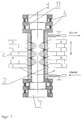
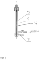
- FIG. 2 an electrode block and in FIG. 3 a gas supply.
- the device for coating elongated flexible products 7 consists of six electrode blocks 1. Two electrode blocks 1 arranged vertically one above the other are arranged parallel to one another.
- the electrode blocks 1 each consist of a hollow long cathode 2, two cylinder anodes 3 arranged on the end faces of the long cathodes 2 and insulating elements 4 which are arranged between the long cathode 2 and the cylinder anodes 3. Furthermore, electrically insulated screens 11 with a cylindrical inner cavity are arranged on the insulating elements 4 between the long cathode 2 and the cylinder anodes 3.
- the long cathode 2, the cylinder anodes 3, the insulating elements 4 and the screens 11 are arranged coaxially to one another.
- the device also contains a system for transporting and for winding and unwinding 6 of elongated flexible products 7. Furthermore, vacuum chambers 8 are provided which are arranged perpendicular to the electrode blocks 1 and are electrically insulated therefrom and for receiving elements of the system for transporting, opening - And unwinding 6 of elongated flexible products 7 serve.
- the inner cavities of the electrode blocks 1 and the vacuum chambers 8 are connected to one another.
- the gas supply 9 in the device consists of the housing 14 with a thermal resistor 15 and the needle valve 12 and is arranged between the unwinding and winding elements of the system for transporting, winding and unwinding 6 of elongated flexible products 7.
- the housing 14 is made of a material with a large coefficient of expansion and the needle valve 12 is made of a material with a small coefficient of expansion, whereby the needle valve 12 can be moved in the housing 14 depending on the temperature.
- the thermal resistor 15 serves to control the temperature of the housing 14 and at the same time as an encoder for the feedback to a control device.
- the device contains the arrangement for generating the magnetic field 5, which consists of three or more plates made of a material with high magnetic permeability with permanent magnets with alternating polarity installed between them, which are arranged coaxially to the axis of the long cathode 2.
- the plates with the permanent magnets move along the longitudinal axis of the long cathode 2 and around this axis.
- the long cathode 2, the cylinder anodes 3 and the screens 11 represent cylinders which can be dismantled, and the inside diameter of the cathode cylinder should be between 0.01-0.5 m, the ratio between its length and its inside diameter being> 2.
- the long cathode 2 is arranged between the cylinder anodes 3.
- the surface line length of the anode cylinders 3 and the shields 11 is chosen in view of the need to secure the shielding of the insulating elements 4 against the atomizing material of the long cathode 2.
- the current source 10 is to be connected to the electrode block 1 for generating potential on the surface of the long cathode 2.
Abstract
Die Erfindung bezieht sich auf das Gebiet der Metallurgie und betrifft eine Vorrichtung zum Beschichten von langgestreckten biegsamen Erzeugnissen, wie z.B. Drähte, Fasern. Der Erfindung liegt die Aufgabe zugrunde, eine Vorrichtung anzugeben, bei der vertikal durchzuziehende Erzeugnisse mit gleichmäßiger Schichtdicke beschichtet werden können. Die Aufgabe wird gelöst durch eine Vorrichtung, enthaltend Elektrodenblöcke, die aus hohlen zylindrischen Langkatoden und aus an den Stirnseiten der Langkatoden angebrachten Zylinderanoden und dazwischen angeordneten Isolierelementen mit einer gemeinsamen Mittelachse bestehen, Anordnungen zur Erzeugung eines Magnetfeldes, Anlagen zum Transportieren, Auf- und Abspulen der langgestreckten biegsamen Erzeugnisse, eine oder mehrere Vakuumkammern, mindestens eine Gaszuführung und eine Stromquelle, wobei bei der Vorrichtung mindestens zwei Elektrodenblöcke vertikal übereinander, die Anordnungen zur Erzeugung eines Magnetfeldes an der hohlen zylindrischen Langkatoden drehbar um und verschiebbar entlang der Langkatodenachse, und elektrisch isolierende Schirme zwischen den Langkatoden und den Zylinderanoden auf den Isolierelementen angeordnet sind. <IMAGE>The invention relates to the field of metallurgy and relates to an apparatus for coating elongated flexible products such as e.g. Wires, fibers. The invention has for its object to provide a device in which products to be drawn vertically can be coated with a uniform layer thickness. The object is achieved by a device comprising electrode blocks which consist of hollow cylindrical long cathodes and cylinder anodes attached to the end faces of the long cathodes and insulating elements arranged between them with a common central axis, arrangements for generating a magnetic field, systems for transporting, winding and unwinding the elongated flexible products, one or more vacuum chambers, at least one gas supply and a power source, with the device at least two electrode blocks vertically one above the other, the arrangements for generating a magnetic field on the hollow cylindrical long cathode rotatable and slidable along the long cathode axis, and electrically insulating shields between the long cathodes and the cylinder anodes are arranged on the insulating elements. <IMAGE>
Description
Die Erfindung bezieht sich auf die Gebiete der Metallurgie, der Kabelindustrie und des Gerätebaus und betrifft eine Vorrichtung zum Beschichten von langgestreckten biegsamen Erzeugnissen, wie z.B. Drähte, Fasern, Fäden, mittels Katodenzerstäubung in Gasatmosphäre bei Niederdruck, die z.B. als Spezialdrähte oder als Drahtseile mit verbesserter Qualität zur Anwendung kommen.The invention relates to the fields of metallurgy, the cable industry and device construction and relates to an apparatus for coating elongated flexible products, such as e.g. Wires, fibers, threads, by means of cathode sputtering in a gas atmosphere at low pressure, which e.g. as special wires or as wire ropes with improved quality.
Bekannt ist eine Vorrichtung zum Auftragen eines Metallüberzugs auf Metallerzeugnisse mittels der kontinuierlichen Aufbringung des feinpulvrigen Überzugsmaterials auf die Oberfläche des sich horizontal bewegenden Stahlbandes ( US 2812270). Diese Vorrichtung besteht aus zwei Vakuumkammern. Eine Vakuumkammer dient zur Aufbringung des Beschichtungsmaterials und die andere zum Erwärmen des Stahlbandes. Mit Hilfe einer Transporteinrichtung mit Abspul- und Aufspuleinrichtungen wird das Stahlband durch diese Vakuumkammern gezogen, wobei ein Aluminiumüberzug aufgebracht wird. Mindestens im Bereich der Beschichtung bewegt sich das Stahlband horizontal.
Diese Vorrichtung wird aber nur zum Auftragen eines Metallüberzugs auf Stahlbänder verwendet. Bei der Anwendung dieser Vorrichtung zum Beschichten von Draht, Fasern oder Fäden würden große Verluste an Zerstäubungsmaterial wegen der kleinen Querschnitte auftreten. Es gibt auch Beschränkungen in Bezug auf die zur Anwendung kommenden Zerstäubungsmaterialien.A device is known for applying a metal coating to metal products by means of the continuous application of the fine powder coating material to the surface of the horizontally moving steel strip (US 2812270). This device consists of two vacuum chambers. One vacuum chamber is used to apply the coating material and the other to heat the steel strip. With the help of a transport device with unwinding and unwinding devices, the steel strip is through them Vacuum chambers drawn, with an aluminum coating is applied. The steel strip moves horizontally at least in the area of the coating.
However, this device is only used to apply a metal coating to steel strips. When using this device for coating wire, fibers or threads, large losses of atomizing material would occur because of the small cross sections. There are also restrictions on the atomizing materials used.
Langgestreckte biegsame Erzeugnisse können bekanntermaßen mittels der Gasphasen- und Vakuumabscheidung beschichtet werden. Unter den Vorrichtungen zum Beschichten mittels Gasphasenmethode ist die Vorrichtung zum Überziehen von Draht mit schwerschmelzbarem Metall (US 4357365) bei kontinuierlichem Durchlauf von Draht in vertikaler Richtung zur Kammerachse bekannt. Sie besteht aus einer Beschichtungskammer mit Eintritts- und Austrittsöffnungen für die Gasmischung, einer Transportanlage mit Abspul- und Aufspulvorrichtungen zur Drahtbeförderung und einer an die Kontakte der Beschichtungskammer angeschlossenen Stromquelle zum Erwärmen des Drahtes.
Eine solche Vorrichtung hat einen begrenzten Anwendungsbereich, da sie zum Beschichten von nicht elektrisch leitenden Fäden oder Fasern nicht geeignet ist. Außerdem hat die Gasphasenmethode zum Beschichten von Draht eine geringere Leistung im Vergleich zur Vakuumabscheidemethode.It is known that elongated, flexible products can be coated by means of gas phase and vacuum deposition. Among the devices for coating by means of the gas phase method, the device for coating wire with fusible metal (US 4357365) with continuous passage of wire in the vertical direction to the chamber axis is known. It consists of a coating chamber with inlet and outlet openings for the gas mixture, a transport system with unwinding and winding devices for wire transport and a current source connected to the contacts of the coating chamber for heating the wire.
Such a device has a limited area of application since it is not suitable for coating non-electrically conductive threads or fibers. In addition, the gas phase method for coating wire has a lower performance compared to the vacuum deposition method.
Zu den Vorrichtungen zum Beschichten mittels Vakuumabscheidung gehört die Magnetronzerstäubungsvorrichtung (PCT 092/01082), die aus einem Elektrodenblock mit einer hohlen zylindrischen Langkatode und in deren Nähe angeordneten Anoden besteht. Die Innenfläche der Katode ist mit dem Zerstäubungsmaterial bedeckt. Die Vorrichtung enthält fest eingebaute Magnete, die die hohle Langkatode umfassen. Das Aufstäuben wird auf den sich horizontal bewegenden Träger, der sich außerhalb des Innenhohlraumes der Katode befindet, durch eine Öffnung in der Katodenwand durchgeführt.
Solche Vorrichtungen haben den Vorteil, daß sich die Verluste des Katodenmaterials verringern und die Katodenzerstäubung durch die Anwendung von Magneten gleichmäßiger erfolgt.
Der Nachteil dieser Vorrichtung ist aber, daß sie zum Beschichten von flachem Trägermaterial dient, das wegen seiner Maße nicht in der Katode angeordnet werden kann, wodurch sich die Aufstäuberate und die Leistung der Vorrichtung verringert.The devices for coating by means of vacuum deposition include the magnetron sputtering device (PCT 092/01082), which consists of an electrode block with a hollow cylindrical long cathode and anodes arranged in the vicinity thereof. The inside surface of the cathode is covered with the atomizing material. The device contains built-in magnets that encircle the hollow long cathode. The sputtering is carried out on the horizontally moving carrier, which is located outside the inner cavity of the cathode, through an opening in the cathode wall.
Such devices have the advantage that the losses of the cathode material are reduced and the cathode sputtering is carried out more evenly by the use of magnets.
The disadvantage of this device, however, is that it is used to coat flat substrate material which, because of its size, cannot be arranged in the cathode, which reduces the dusting rate and the performance of the device.
Weiterhin sind Magnetron-Vorrichtungen zur Beschichtung von Substraten bekannt (US 4960753). Diese Magnetron-Vorrichtung besteht aus mehreren Einzelvorrichtungen, die übereinander angeordnet sind. In jeder einzelnen Vorrichtung wird das durchlaufende Substrat mit unterschiedlichen Materialien beschichtet. Eine dieser Vorrichtungen besteht aus einer zylindrischen Anode, einer zylindrischen Katode, die mit einem größeren Durchmesser um die Anode herum angeordnet ist, und aus einer Vorrichtung zur Erzeugung eines Magnetfeldes, die ebenfalls mit einem größeren Druchmesser um die Katode herum angeordnet ist. Bei dieser Anordnung ist die Anode prinzipiell bezüglich der Längsachse der Zylinderanordnung innenliegend.
Diese Anordnung ist typisch für ein Magnetron.Furthermore, magnetron devices for coating substrates are known (US 4960753). This magnetron device consists of several individual devices which are arranged one above the other. In each individual device, the continuous substrate is coated with different materials. One of these devices consists of a cylindrical anode, a cylindrical cathode which is arranged around the anode with a larger diameter, and a device for producing it of a magnetic field, which is also arranged with a larger diameter around the cathode. In this arrangement, the anode is in principle internal with respect to the longitudinal axis of the cylinder arrangement.
This arrangement is typical of a magnetron.
Der Nachteil dieser Vorrichtung besteht darin, daß die Anode dem Beschichtungsmaterial ausgesetzt ist und daß durch das so angeordnete Magnetfeld nur ein kreisförmiges Magnetfeld erzeugt werden kann.The disadvantage of this device is that the anode is exposed to the coating material and that only a circular magnetic field can be generated by the magnetic field thus arranged.
Es ist auch eine Elektrodenaufladevorrichtung zur Materialzerstäubung und Abscheidung auf langgestreckte biegsame Erzeugnisse bekannt (z.B. auf Draht), die in der Gasatmosphäre bei einem Druck von kleiner gleich 13,2 Pa horizontal befördert werden (US 3884793). Diese Vorrichtung enthält einen Elektrodenblock, der aus einer hohlen lange Zylinderkatode zwischen zwei koaxial dazu eingebauten Zylinderanoden und aus den zwischen der Katode und den Anoden angeordneten Isolierelementen besteht. Die Innenfläche der Katode ist mit dem Zerstäubungsmaterial bedeckt. Die Vorrichtung enthält ebenfalls Magnete zur Erzeugung von Magnetfeldern in der Katode, die zu der Katodenlängsachse parallel wirken. Die Magnete umschließen den Elektrodenblock und sind als fest eingebaute Magnetspulen auf ferromagnetischen Platten ausgeführt. Der Innenhohlraum der Katode steht in Verbindung mit dem Innenhohlraum der Vakuumkammer, in die man die Transportanlage für die Beförderung der zu beschichtenden Erzeugnisse einschließlich der Abspul- und Aufspuleinrichtungen einbaut. In der Vorrichtung sind Gaszuführungseinrichtungen und eine an den Elektrodenblock angeschlossene Stromquelle vorgesehen.
Nachteilig an dieser Vorrichtung ist aber eine geringe Leistung, weil der Draht horizontal durchgezogen wird und es unmöglich ist, in einem Durchgang durch die Katode die Solldicke der Deckschicht zu sichern. Im Zusammenhang damit, daß die Magnete in der Vorrichtung gegen die Katode unbeweglich sind und die Katode eine große Länge hat, verschleißt das Katodenmaterial ungleichmäßig, da die Entfernung von der Katodenmitte größer als der Abstand zwischen der Katode und jeder Anode ist. Diese Vorrichtung hat außerdem eine kurze Lebensdauer, da eine Schutzvorrichtung gegen die ungewünschte Beschichtung der zwischen der Katode und den Anoden angeordneten Isolierelemente fehlt.There is also known an electrode charging device for material atomization and deposition on elongated flexible products (for example on wire) which are conveyed horizontally in the gas atmosphere at a pressure of less than or equal to 13.2 Pa (US 3884793). This device contains an electrode block which consists of a hollow long cylinder cathode between two cylinder anodes installed coaxially thereto and of the insulating elements arranged between the cathode and the anodes. The inside surface of the cathode is covered with the atomizing material. The device also contains magnets for generating magnetic fields in the cathode, which act parallel to the longitudinal axis of the cathode. The magnets enclose the electrode block and are designed as permanently installed magnetic coils on ferromagnetic plates. The inner cavity of the cathode communicates with the inner cavity of the vacuum chamber into which the transport system for the transport of the products to be coated, including the Unwinding and winding devices installed. Gas supply devices and a current source connected to the electrode block are provided in the device.
A disadvantage of this device, however, is low power because the wire is pulled horizontally and it is impossible to secure the desired thickness of the cover layer in one pass through the cathode. In connection with the fact that the magnets in the device are immovable against the cathode and the cathode is of great length, the cathode material wears out unevenly since the distance from the center of the cathode is greater than the distance between the cathode and each anode. This device also has a short lifespan because there is no protective device against the undesired coating of the insulating elements arranged between the cathode and the anodes.
Der Erfindung liegt die Aufgabe zugrunde, eine Vorrichtung zum Beschichten von langgestreckten biegsamen Erzeugnissen mittels der Katodenzerstäubung anzugeben, bei der vertikal durchzuziehende Erzeugnisse mit gleichmäßiger Schichtdicke, mit geringen Aufdampfmaterialverlusten und hohem Durchsatz beschichtet werden können.The invention has for its object to provide a device for coating elongated flexible products by means of cathode sputtering, in which products to be drawn vertically can be coated with a uniform layer thickness, with low evaporation material losses and high throughput.
Die Aufgabe wird durch die in den Ansprüchen angegebene Erfindung gelöst.The object is achieved by the invention specified in the claims.
Die erfindungsgemäße Vorrichtung zum Beschichten von langgestreckten biegsamen Erzeugnissen enthält Elektrodenblöcke, die aus hohlen zylindrischen Langkatoden und aus an den Stirnseiten der Langkatoden angebrachten Zylinderanoden und dazwischen angeordneten Isolierelementen mit einer gemeinsamen Mittelachse bestehen, wobei die Langkatoden auf ihrer Mantelinnenoberfläche mit Targetmaterialien beschichtet sind oder vollständig aus dem Targetmaterial bestehen. Dabei sind erfindungsgemäß mindestens zwei Elektrodenblöcke vertikal übereinander angeordnet.The device according to the invention for coating elongated flexible products contains electrode blocks which consist of hollow cylindrical long cathodes and cylinder anodes attached to the end faces of the long cathodes and insulating elements arranged therebetween with a common central axis, the long cathodes being coated on their inner surface with target materials or entirely from the same Target material exist. According to the invention, at least two electrode blocks are arranged vertically one above the other.
Weiterhin enthält die Vorrichtung Anordnungen zur Erzeugung eines Magnetfeldes, die die hohlen zylindrischen Langkatoden umschließen. Diese Anordnungen sind erfindungsgemäß um die hohlen zylindrischen Langkatoden herum drehbar um und verschiebbar entlang der Langkatodenachse angeordnet.The device also contains arrangements for generating a magnetic field, which enclose the hollow cylindrical long cathodes. According to the invention, these arrangements are arranged around the hollow cylindrical long cathodes so as to be rotatable and displaceable along the long cathode axis.
Ebenfalls enthält die Vorrichtung Anlagen zum Transportieren und Auf- und Abspulen der langgestreckten biegsamen Erzeugnisse.The device also contains systems for transporting and winding and unwinding the elongated flexible products.
Im weiteren sind eine oder mehrere Vakuumkammern vorhanden, die mindestens die Langkatoden und die Anlagen zum Transportieren der langgestreckten biegsamen Erzeugnisse aufnehmen, wobei diese in einer gemeinsamen oder in getrennten Vakuumkammern untergebracht sein können.Furthermore, there are one or more vacuum chambers which accommodate at least the long cathodes and the systems for transporting the elongated, flexible products, which can be accommodated in a common or in separate vacuum chambers.
Außerdem sind noch mindestens eine Gaszuführung und eine Stromquelle vorhanden.There is also at least one gas supply and a power source.
Erfindungsgemäß enthält die Vorrichtung weiterhin elektrisch isolierende Schirme, die zwischen den Langkatoden und den Zylinderanoden auf den Isolierelementen angeordnet sind, wobei der Innendurchmesser der Schirme größer als der Innendurchmesser der Langkatode und kleiner als der Durchmesser der Innenhohlräume der Zylinderanode ist.According to the invention, the device further contains electrically insulating screens which are arranged between the long cathodes and the cylinder anodes on the insulating elements, the inside diameter of the screens being larger than the inside diameter of the long cathode and smaller than the diameter of the interior cavities of the cylinder anode.
Vorteilhafterweise sind beim Einsatz von mehr als zwei Elektrodenblöcken, diese in einer vertikalen Reihe angeordnet.When using more than two electrode blocks, these are advantageously arranged in a vertical row.
Weiterhin sind vorteilhafterweise beim Einsatz von mehr als zwei Elektrodenblöcken, jeweils mindestens zwei vertikal übereinander angeordnete Elektrodenblöcke parallel nebeneinander angeordnet.Furthermore, when using more than two electrode blocks, at least two electrode blocks arranged vertically one above the other are advantageously arranged in parallel next to one another.
Ebenfalls vorteilhafterweise befindet sich die Gaszuführung zwischen den Anlagen zum Auf- und Abspulen der langgestreckten biegsamen Erzeugnisse, wobei die Gasströmungsrichtung entgegen der Bewegungsrichtung der langgestreckten biegsamen Erzeugnisse gerichtet ist.The gas supply is also advantageously located between the systems for winding and unwinding the elongated flexible products, the direction of gas flow being directed against the direction of movement of the elongated flexible products.
Und ebenfalls vorteilhaft ist es, daß die Schirme zerlegbar sind.And it is also advantageous that the screens can be dismantled.
Der vertikale Aufbau der Vorrichtung ermöglicht es, daß die langgestreckten biegsamen Erzeugnisse mit gleichmäßiger Schichtdicke, mit geringen Targetmaterialverlusten und mit einem hohen Durchsatz beschichtet werden können.
Dabei ist es notwendig, die Erzeugnisse genau senkrecht oder in einem die Katodenachse entlang und zu ihr symmetrisch liegenden Bereich mit einem Radius , der 0,2 vom Katodenradius beträgt, zu transportieren, da davon die Gleichmäßigkeit des Beschichtens von Erzeugnissen abhängt. Falls die Abweichung von der Senkrechten bei der Bewegung von Erzeugnissen den angegebenen Wert überschreitet, entstehen Probleme beim Transportieren der Erzeugnisse. Wegen des Durchhangs fällt die Aufdampfgleichmäßigkeit ab und es entstehen Zusatzbelastungen in der Transportanlage, weil Zusatzkräfte zum Spannen der Erzeugnisse angelegt werden müssen.The vertical structure of the device enables the elongated flexible products to be of uniform layer thickness, with low target material losses and with a high level Throughput can be coated.
It is necessary to transport the products exactly vertically or in a region along the cathode axis and symmetrical to it with a radius that is 0.2 from the cathode radius, since the uniformity of the coating of products depends on this. If the deviation from the vertical when moving products exceeds the specified value, problems arise when transporting the products. Due to the sag, the evaporation evenness drops and additional loads arise in the transport system because additional forces have to be applied to clamp the products.
Durch den Einbau von weiteren Elektrodenblöcken, die vertikal zu den Vakuumkammern eingebaut und gegen diese elektrisch isoliert sind, wird erreicht, daß die Abscheidung des Targetmateials auf die Erzeugnisse mit hoher Geschwindigkeit erfolgt, aber gleichzeitig die Isolierung der Elektrodenblöcke gegen die Vakuumkammer gesichert ist, wodurch eine zuverlässige Funktion (Fehlen von Durchschlägen) durch Abschirmung vor dem Beschlagen mit Targetmaterial erreicht wird. Deswegen ist es günstiger, mehrere Elektrodenblöcke zu verwenden und Vakuumentladungen dazwischen aufrechtzuerhalten.
Die in der Vorrichtung vorhandene Anordnung zur Erzeugung des Magnetfeldes besteht aus die Katode umfassenden Platten, aus einem Material mit hoher magnetischer Durchlässigkeit, mit dazwischen angeordneten Dauermagneten, die eine sich abwechselnde Polarität haben. Für die Überführung der Entladung in den Magnetronbetriebszustand ist es notwendig, an der Oberfläche der Langkatode ein Bogenmagnetfeld zu erzeugen. Dazu dienen die Platten, die mit Hilfe der Dauermagneten magnetisiert werden. Bei Dauerbetrieb der Vorrichtung ist es nötig, die Bewegung des Bogenmagnetfeldes der Langkatodenoberfläche gegenüber zu sichern; infolge der Ungleichmäßigkeit der Magnetisierung der Platten mit Hilfe von Dauermagneten bewegt man die Anordnung zur Erzeugung des Magnetfeldes entlang der Längsachse der Langkatode und um diese Achse herum, um die gleichmäßige Beschichtung von Erzeugnissen und die gleichmäßige Zerstäubung des Targetmaterials zu erreichen.By installing further electrode blocks, which are installed vertically to the vacuum chambers and are electrically insulated against them, it is achieved that the deposition of the target material onto the products takes place at high speed, but at the same time the insulation of the electrode blocks is secured against the vacuum chamber, thereby ensuring a reliable function (lack of breakthroughs) is achieved by shielding before fogging with target material. Because of this, it is cheaper to use multiple electrode blocks and maintain vacuum discharges between them.
The arrangement in the device for generating the magnetic field consists of plates comprising the cathode, made of a material with high magnetic permeability, with permanent magnets arranged in between, which have an alternating polarity. For transferring the discharge to the magnetron operating state it is necessary to generate an arc magnetic field on the surface of the long cathode. The plates, which are magnetized with the help of permanent magnets, serve this purpose. During continuous operation of the device, it is necessary to secure the movement of the arc magnetic field against the long cathode surface; due to the non-uniformity of the magnetization of the plates with the aid of permanent magnets, the arrangement for generating the magnetic field is moved along the longitudinal axis of the long cathode and around this axis in order to achieve the uniform coating of products and the uniform atomization of the target material.
Die Elektrodenblöcke in der Vorrichtung können in einer vertikalen Linie, einer nach dem anderen, angeordnet werden. Diese Anordnung hat besondere Vorteile, wenn damit dünne Erzeugnisse und Erzeugnisse mit geringer mechanischer Festigkeit bedampft werden sollen. Damit wird ein abrißfreier Vorschub beim Aufdampfen die in der Transportanlage gesichert.The electrode blocks in the device can be arranged in a vertical line, one after the other. This arrangement has particular advantages if thin products and products with low mechanical strength are to be steamed with them. This ensures a tear-free feed during vapor deposition in the transport system.
Die erfindungsgemäße Vorrichtung enthält weiterhin elektrisch isolierte Schirme mit zylindrischen Innenhohlräumen, die in den Elektrodenblock zwischen der Langkatode und den Zylinderanoden eingebaut sind. Das ist erforderlich, um eine stabile Entladung und die Reproduzierbarkeit der Beschichtung zu sichern, da von der Geometrie der Innenflächen der Langkatode, der Zylinderanoden und der elektrisch isolierten Schirme die Parameter der Entladung abhängen, die für das Aufstäuben auf die Erzeugnisse entscheidend sind. Dabei ist der Innendurchmesser der elektrisch isolierten Schirme größer als der Innendurchmesser der Langkatode und kleiner als der Innendurchmesser der Zylinderanoden. Das ist erforderlich, um die Isolierelemente gegenüber Beschlagen durch das Katodenmaterial zu sichern, da die Lebensdauer der Vorrichtung in hohem Maße auch von diesem unerwünschten Beschlagen der Isolierelemente abhängt. Zu diesem Zweck sind Langkatode, Zylinderanoden und elektrisch isolierte Schirme zerlegbar ausgeführt und die Innendurchmesser sind kleiner als der Durchmesser der Isolierelemente.The device according to the invention also contains electrically insulated screens with cylindrical inner cavities, which are installed in the electrode block between the long cathode and the cylinder anodes. This is necessary to ensure a stable discharge and the reproducibility of the coating, since the parameters of the discharge depend on the geometry of the inner surfaces of the long cathode, the cylinder anodes and the electrically insulated screens depend on which are crucial for dusting on the products. The inside diameter of the electrically insulated screens is larger than the inside diameter of the long cathode and smaller than the inside diameter of the cylinder anodes. This is necessary to secure the insulating elements against fogging by the cathode material, since the service life of the device also depends to a large extent on this undesirable fogging of the insulating elements. For this purpose, the long cathode, cylinder anodes and electrically insulated shields can be dismantled and the inner diameter is smaller than the diameter of the insulating elements.
Die Anordnung der Gaszuführungseinrichtung zwischen den Anlagen zum Auf- und Abspulen der langgestreckten biegsamen Erzeugnisse sichert die Erhöhung der Deckschichtqualität und gleichzeitig den Schutz der Anlage zum Transportieren und Auf- und Abspulen der langgestreckten biegsamen Erzeugnisse gegen das Beschlagen durch die Wahl der Führung des Gasgemisches von der Gaszuführungseinrichtung durch die Innenhohlräume der Langkatoden in die Vakuumkammern. Die Deckschichtqualität erhöht sich mit der Verminderung der Menge an Fremdstoffen, die damit während des Abdampfens von den Anlagen zum Transportieren, Auf- und Abspulen der langgestreckten biegsamen Erzeugnisse durch den Gegenstrom nicht in die Innenhohlräume der Langkatoden eindringen können.The arrangement of the gas supply device between the systems for winding and unwinding the elongated flexible products ensures the increase in the top layer quality and at the same time the protection of the system for transporting and winding and unwinding the elongated flexible products against fogging by the choice of the guidance of the gas mixture from the Gas supply device through the inner cavities of the long cathodes into the vacuum chambers. The quality of the cover layer increases with the reduction in the amount of foreign substances which, as a result of the countercurrent, cannot penetrate into the inner cavities of the long cathodes during evaporation from the systems for transporting, winding and unwinding the elongated flexible products.
Zwecks der Leistungserhöhung der Vorrichtung werden jeweils zwei vertikal übereinander angeordnete Elektrodenblöcke parallel zueinander angeordnet.
Die Vorrichtung zum Beschichten von langgestreckten biegsamen Erzeugnissen funktioniert folgendermaßen.In order to increase the power of the device, two electrode blocks arranged vertically one above the other are made parallel arranged to each other.
The device for coating elongated flexible products works as follows.
Die zu beschichtenden langgestreckten biegsamen Erzeugnisse werden auf die Anlage zum Transportieren und Auf- und Abspulen der langgestreckten biegsamen Erzeugnisse gelegt. Danach werden die Vakuumkammern evakuiert. Anschließend wird die Gaszuführung erwärmt. Nach Erreichen der gewünschten Temperatur wird die Gaszuführung geöffnet und in den Innenhohlraum der Langkatode tritt die Gasmischung ein. Die gleichmäßige Zufuhr wird durch die Temperaturkontrolle der Gaszuführung z.B. mit Hilfe eines Thermowiderstandes gesichert. Mit Hilfe der Stromquelle wird ein Potential auf der Oberfläche der Langkatode erzeugt und die elektrische Entladung in der Langkatode wird im vorgegebenen Kapazitätsbereich (z.B. 1000 W) aufrechterhalten.The elongated flexible products to be coated are placed on the system for transporting and winding and unwinding the elongated flexible products. The vacuum chambers are then evacuated. The gas supply is then heated. After the desired temperature has been reached, the gas supply is opened and the gas mixture enters the inner cavity of the long cathode. The uniform supply is controlled by the temperature control of the gas supply e.g. secured with the help of a thermal resistor. With the help of the power source, a potential is generated on the surface of the long cathode and the electrical discharge in the long cathode is maintained in the specified capacity range (e.g. 1000 W).
Um den Targetwerkstoff voll auszunutzen und die Betriebszeit der Vorrichtung zu verlängern, sind die Zylinderanoden von der Langkatode durch die elektrisch isolierten Schirme abgetrennt. Die elektrischen Isolierelemente dienen auch als Vakuumdichtung.In order to take full advantage of the target material and to extend the operating time of the device, the cylinder anodes are separated from the long cathode by the electrically insulated screens. The electrical insulation elements also serve as a vacuum seal.
Zur Leistungserhöhung bewegt sich die Anordnung zur Erzeugung des Magnetfeldes mit den Platten und dem Dauermagneten während des Beschichtens gegenüber der Langkatode. Als Ergebnis der Vakuumentladung in der Langkatode, die zur Leistungserhöhung auf den Magnetronbetriebszustand umgestellt ist, bildet sich auf den zu beschichtenden Erzeugnissen eine geschlossene Deckschicht aus dem Targetmaterial und zwar mit hoher Homogenität bezüglich Länge und Umfang des Erzeugnisses.To increase the power, the arrangement for generating the magnetic field with the plates and the permanent magnet moves relative to the long cathode during coating. As a result of the vacuum discharge in the long cathode, which increases the output on the When the magnetron operating state is changed, a closed cover layer is formed from the target material on the products to be coated, with a high degree of homogeneity with regard to the length and circumference of the product.
Zur Sicherung der stabilen Funktion der Langkatode im Magnetronbetriebszustand wird der Druck der Gasmischung im Bereich 10 - 0,01 mm Hg aufrechterhalten, dabei erhöht sich die Geschwindigkeit der Gasphasenerzeugung vom Werkstoff der Langkatode und die Konstanz der Beschichtungsparameter der Vorrichtung.To ensure the stable functioning of the long cathode in the magnetron operating state, the pressure of the gas mixture is maintained in the range 10-0.01 mm Hg, the speed of the gas phase generation from the material of the long cathode and the constancy of the coating parameters of the device increase.
Während des Beschichtungsvorganges werden die Erzeugnisse in vertikaler Richtung mit der Geschwindigkeit von 0,01 - 10 m/min die Katodenachse entlang transportiert. Dieser Geschwindigkeitsbereich ist aus folgenden Gründen gewählt worden:
Bei einer Geschwindigkeit unter 0,1 m/min tritt eine bedeutende Erwärmung der Erzeugnisse auf, was häufig Brüche zur Folge hat; außerdem ist die Vorrichtung bei solchen Geschwindigkeiten wenig effektiv. Beim Transport über 20 m/min ist es kompliziert, die Eigenschwingungen der Erzeugnisse zu beherrschen und annehmbare minimale Schichtdicken zu erreichen.During the coating process, the products are transported along the cathode axis in the vertical direction at a speed of 0.01 - 10 m / min. This speed range was chosen for the following reasons:
At a speed of less than 0.1 m / min, the products heat up significantly, which often results in breaks; moreover, the device is not very effective at such speeds. When transporting above 20 m / min, it is difficult to master the natural vibrations of the products and to achieve acceptable minimum layer thicknesses.
Eine Verbesserung der Deckschichtqualität und die Erhöhung der Beschichtungsrate können in dieser Vorrichtung mittels der Zuführung von einer Gasmischung in den Hohlraum der Langkatode erreicht werden. Z.B. steigt bei der Zuführung einer Argon-Xenon-Mischung die Beschichtungsrate an. Die Zugabe von Ammoniak zu der Gasmischung hat sowohl die Erhöhung der Beschichtungsrate als auch die Verbesserung der Schichtqualität zur Folge. Die Zugabe von Helium verbessert die Qualität infolge Porositätsverminderung.An improvement in the top layer quality and an increase in the coating rate can be achieved in this device by supplying a gas mixture into the cavity of the long cathode. For example, when adding an argon-xenon mixture, the coating rate increases. The addition of ammonia to the Gas mixing results in both an increase in the coating rate and an improvement in the layer quality. The addition of helium improves the quality due to the reduction in porosity.
Das Arbeitsgas wird nach dem Austritt aus der Vakuumkammer gesammelt und erneut dem Innenhohlraum der Langkatode zugeführt.After exiting the vacuum chamber, the working gas is collected and fed again into the inner cavity of the long cathode.
Bei der Funktion der Vorrichtung nach dem Entladungsprinzip mit einer Langkatode hat die Reinheit des Targetwerkstoffs wegen des Materialübertrags auf die Erzeugnisse eine große Bedeutung. Da beim Materialübertrag auch eine Gasabscheidung stattfindet, ist die Reinheit des zu verwendenden Gases sehr wichtig. Selbst geringe Beimischungen von aktiven Gasen, z.B. von Sauerstoff und Stickstoff, haben beim mehrfachen Targetmaterialübertrag einen großen Einfluß auf die chemische Zusammensetzung der hergestellten Deckschichten. Andererseits wird das Gas nach dem Durchgang des Hohlraumes der Langkatode von reaktiven Beimischungen infolge ihrer Adsorbtion mit dem Targetwerkstoff, der bei der Beschichtung übertragen wird, gereinigt. Es ist zweckmäßig, solch ein gereinigtes Gas wieder für die Arbeit zu verwenden. Außerdem ist die Einsparung von so kostspieligen Gasen, wie Helium, Krypton und Xenon ein nicht unbedeutender wirtschaftlicher Faktor.When the device works according to the discharge principle with a long cathode, the purity of the target material is of great importance because of the material transfer to the products. Since gas separation also takes place during material transfer, the purity of the gas to be used is very important. Even small admixtures of active gases, e.g. of oxygen and nitrogen, have a major influence on the chemical composition of the cover layers when multiple target material transfer. On the other hand, after passing through the cavity of the long cathode, the gas is cleaned of reactive admixtures as a result of their adsorption with the target material which is transferred during the coating. It is advisable to reuse such a cleaned gas for work. In addition, the saving of such expensive gases as helium, krypton and xenon is a not insignificant economic factor.
Die Gasmischung kann inerte und reaktive Gase enthalten. Das ermöglicht, unterschiedliche Typen von isolierenden, verschleißfesten oder dekorativen Deckschichten herzustellen. Bei der Zuführung von Sauerstoff ist es z.B. möglich, isolierende oder verschleißfeste Deckschichten auf Grundlage von Oxiden herzustellen, weil bei der Verwendung einer Aluminiumkatode die hergestellten Deckschichten gute Isoliereigenschaften und eine gute Verschleißfestigkeit haben; bei der Verwendung von Stickstoff als reaktives Gas kann man dekorative Deckschichten aus Titannitrid herstellen, usw.The gas mixture can contain inert and reactive gases. This enables different types of insulating, wear-resistant or to produce decorative cover layers. When adding oxygen, it is possible, for example, to produce insulating or wear-resistant cover layers based on oxides, because when using an aluminum cathode, the cover layers produced have good insulating properties and good wear resistance; When using nitrogen as a reactive gas, decorative cover layers can be made from titanium nitride, etc.
Bei der Beschichtung von elektrisch leitfähigen Teilen sind neue Behandlungsprinzipien möglich. Um eine Wärmebehandlung durchzuführen, reicht es aus, den Teilen ein positives Potential gegenüber dem Plasma anzulegen, daraufhin werden sie sich infolge der Bombardierung durch Elektronen erwärmen. Man kann den Erwärmungsgrad mittels der Potentialwertänderung regeln. Wird ein negatives Potential an das Erzeugnis angelegt, wird es dem Ionenbombardement ausgesetzt, was auch zu seiner Erwärmung führt. Da aber die Elektronenbewegung im Plasma dreimal so hoch wie die Ionenbeweglichkeit ist, ergibt sich eine weniger effektive Erwärmung der Teile durch Ionen als durch Elektronen. Andererseits läßt sich das Ionenbombardement zur Reinigung der Teile und das Beschichten gleichzeitig mit der Bombardierung durch Ionen durchführen, wodurch das Adhäsionsvermögen der Deckschichten und ihre Qualität verbessert werden.New treatment principles are possible when coating electrically conductive parts. In order to carry out a heat treatment, it is sufficient to apply a positive potential to the parts against the plasma, after which they will heat up due to the bombardment by electrons. The degree of heating can be regulated by changing the potential value. If a negative potential is applied to the product, it is exposed to ion bombardment, which also leads to its heating. However, since the electron movement in the plasma is three times higher than the ion mobility, the parts are heated less effectively by ions than by electrons. On the other hand, the ion bombardment for cleaning the parts and the coating can be carried out simultaneously with the bombardment by ions, which improves the adhesiveness of the cover layers and their quality.
Im folgenden ist die Vorrichtung anhand eines Ausführungsbeispiels näher erläutert. Die zugehörigen Zeichnungen zeigen in schematischer Darstellung mit Figur 1 den schematischen Aufbau der erfindungsgemäßen Vorrichtung zum Beschichten von langgestreckten biegsamen Erzeugnissen, in Figur 2 einen Elektrodenblock und in Figur 3 eine Gaszuführung.The device is explained in more detail below using an exemplary embodiment. The associated drawings show in 1 shows the schematic structure of the device according to the invention for coating elongated flexible products, in FIG. 2 an electrode block and in FIG. 3 a gas supply.
Die Vorrichtung zum Beschichten von langgestreckten biegsamen Erzeugnissen 7 besteht aus sechs Elektrodenblöcken 1. Dabei sind jeweils zwei vertikal übereinander angeordnete Elektrodenblöcke 1 parallel zueinander angeordnet. Die Elektrodenblöcke 1 bestehen jeweils aus einer hohlen Langkatode 2, zwei an den Stirnseiten der Langkatoden 2 angeordneten Zylinderanoden 3 und Isolierelementen 4, die zwischen der Langkatode 2 und den Zylinderanoden 3 angeordnet sind. Weiterhin sind elektrisch isolierte Schirme 11 mit zylindrischem Innenhohlraum auf den Isolierelementen 4 zwischen der Langkatode 2 und den Zylinderanoden 3 angeordnet. Die Langkatode 2, die Zylinderanoden 3, die Isolierelemente 4 und die Schirme 11 sind koaxial zueinander angeordnet.The device for coating elongated
Die Vorrichtung enthält auch eine Anlage zum Transportieren und zum Auf- und Abspulen 6 von langgestreckten biegsamen Erzeugnissen 7. Weiterhin sind Vakuumkammern 8 vorhanden, die senkrecht zu den Elektrodenblöcken 1 angeordnet und elektrisch isoliert davon sind und zur Aufnahme von Elementen der Anlage zum Transportieren, Auf- und Abspulen 6 von langgestreckten biegsamen Erzeugnissen 7 dienen. Die Innenhohlräume der Elektrodenblöcke 1 und der Vakuumkammern 8 sind miteinander verbunden.The device also contains a system for transporting and for winding and
Die Gaszuführung 9 in die Vorrichtung besteht aus dem Gehäuse 14 mit einem Thermowiderstand 15 und aus dem Nadelventil 12 und ist zwischen den Abspul- und Aufspulelementen der Anlage zum Transportieren, Auf- und Abspulen 6 von langgestreckten biegsamen Erzeugnissen 7 angeordnet. Das Gehäuse 14 ist aus einem Werkstoff mit großem Ausdehnungskoeffizienten und das Nadelventil 12 aus einem Werkstoff mit kleinem Ausdehnungskoeffizienten hergestellt, wodurch sich das Nadelventil 12 im Gehäuse 14 in Abhängigkeit von der Temperatur bewegen läßt. Der Thermowiderstand 15 dient zur Temperaturkontrolle des Gehäuses 14 und gleichzeitig als Geber für die Rückkopplung zu einer Steuereinrichtung.The
Die Vorrichtung enthält die Anordnung zur Erzeugung des Magnetfeldes 5, die aus drei oder mehr Platten aus einem Werkstoff mit hoher magnetischer Durchlässigkeit mit dazwischen eingebauten Dauermagneten mit sich abwechselnder Polarität besteht, die koaxial zur Achse der Langkatode 2 angeordnet sind. Die Platten mit den Dauermagneten bewegen sich entlang der Längsachse der Langkatode 2 und um diese Achse herum.The device contains the arrangement for generating the
Die Langkatode 2, die Zylinderanoden 3 und die Schirme 11 stellen zerlegbare Zylinder dar, außerdem soll der Innendurchmesser des Katodenzylinders zwischen 0,01 - 0,5 m liegen, wobei das Verhältnis zwischen seiner Länge und seinem Innendurchmesser >2 sein soll. Die Langkatode 2 ist zwischen den Zylinderanoden 3 angeordnet.The
Die Mantellinienlänge der Anodenzylinder 3 und der Schirme 11 wird mit Rücksicht auf die Notwendigkeit gewählt, die Abschirmung der Isolierelemente 4 gegen das Zerstäubungsmaterial der Langkatode 2 zu sichern.The surface line length of the
Die Stromquelle 10 ist zur Potentialerzeugung auf der Oberfläche der Langkatode 2 an den Elektrodenblock 1 anzuschließen.The
Claims (5)
Applications Claiming Priority (2)
| Application Number | Priority Date | Filing Date | Title |
|---|---|---|---|
| DE4333825 | 1993-09-28 | ||
| DE19934333825 DE4333825C1 (en) | 1993-09-28 | 1993-09-28 | Apparatus for coating elongated flexible products |
Publications (1)
| Publication Number | Publication Date |
|---|---|
| EP0647961A1 true EP0647961A1 (en) | 1995-04-12 |
Family
ID=6499383
Family Applications (1)
| Application Number | Title | Priority Date | Filing Date |
|---|---|---|---|
| EP94114602A Ceased EP0647961A1 (en) | 1993-09-28 | 1994-09-16 | Device for coating elongated bendable products |
Country Status (2)
| Country | Link |
|---|---|
| EP (1) | EP0647961A1 (en) |
| DE (1) | DE4333825C1 (en) |
Cited By (5)
| Publication number | Priority date | Publication date | Assignee | Title |
|---|---|---|---|---|
| DE19540053A1 (en) * | 1995-10-27 | 1997-04-30 | Leybold Ag | Substrate coating device for application of non-conductive layers using magnetron sputtering |
| DE19540255A1 (en) * | 1995-10-28 | 1997-04-30 | Leybold Ag | Apparatus for film coating a substrate |
| DE29600991U1 (en) * | 1996-01-20 | 1997-05-22 | Straemke Siegfried Dr Ing | Plasma reactor |
| US6168698B1 (en) | 1995-10-27 | 2001-01-02 | Balzers Und Leybold Deutschland Holding Ag | Apparatus for coating a substrate |
| JP2006117999A (en) * | 2004-10-21 | 2006-05-11 | Hitachi Cable Ltd | Thin film forming method and thin film forming device |
Families Citing this family (5)
| Publication number | Priority date | Publication date | Assignee | Title |
|---|---|---|---|---|
| DE19722056A1 (en) * | 1997-05-27 | 1998-12-03 | Roland Dr Gesche | Method and apparatus for production of thin layers by low pressure gas discharge in a hollow cathode |
| JP4822378B2 (en) | 2001-02-06 | 2011-11-24 | 株式会社ブリヂストン | Film forming apparatus and film forming method |
| DE102010056343A1 (en) | 2010-12-29 | 2012-07-05 | Von Ardenne Anlagentechnik Gmbh | Device for vacuum-thin film coating of rod- or tubular-shaped solid substrates, comprises magnetron as source for coating, where magnetron is aligned on destination and comprises target arranged in sequence starting from destination |
| CZ305631B6 (en) * | 2014-06-25 | 2016-01-13 | Tesla Electrontubes S.R.O. | Apparatus for coating internal cavities of small cross section and large longitudinal dimensions using magnetron-sputtering method |
| DE102015121518A1 (en) | 2015-12-10 | 2017-06-14 | Technische Universität Clausthal | Process and installation for the production of coatings on substrates and a coated wire-shaped substrate |
Citations (3)
| Publication number | Priority date | Publication date | Assignee | Title |
|---|---|---|---|---|
| JPH03100175A (en) * | 1989-09-13 | 1991-04-25 | Seiko Instr Inc | Thin film forming device |
| US5178743A (en) * | 1989-06-15 | 1993-01-12 | Microelectronics And Computer Technology Corporation | Cylindrical magnetron sputtering system |
| US5228963A (en) * | 1991-07-01 | 1993-07-20 | Himont Incorporated | Hollow-cathode magnetron and method of making thin films |
Family Cites Families (6)
| Publication number | Priority date | Publication date | Assignee | Title |
|---|---|---|---|---|
| US2812270A (en) * | 1954-01-28 | 1957-11-05 | Continental Can Co | Method and apparatus for depositing metal coatings on metal bases |
| US3884793A (en) * | 1971-09-07 | 1975-05-20 | Telic Corp | Electrode type glow discharge apparatus |
| US4357365A (en) * | 1980-01-17 | 1982-11-02 | General Electric Company | Refractory metal coating method |
| US4960753A (en) * | 1987-07-29 | 1990-10-02 | Collins George J | Magnetron deposition of ceramic oxide-superconductor thin films |
| US5073245A (en) * | 1990-07-10 | 1991-12-17 | Hedgcoth Virgle L | Slotted cylindrical hollow cathode/magnetron sputtering device |
| GB9121699D0 (en) * | 1991-10-11 | 1991-11-27 | Hacker Dennis J | Volume manufacture of low weight/cost fire stop(proof)doors & partitions with 1/2-1-1 1/2-2-3-4 hour capacities |
-
1993
- 1993-09-28 DE DE19934333825 patent/DE4333825C1/en not_active Expired - Fee Related
-
1994
- 1994-09-16 EP EP94114602A patent/EP0647961A1/en not_active Ceased
Patent Citations (3)
| Publication number | Priority date | Publication date | Assignee | Title |
|---|---|---|---|---|
| US5178743A (en) * | 1989-06-15 | 1993-01-12 | Microelectronics And Computer Technology Corporation | Cylindrical magnetron sputtering system |
| JPH03100175A (en) * | 1989-09-13 | 1991-04-25 | Seiko Instr Inc | Thin film forming device |
| US5228963A (en) * | 1991-07-01 | 1993-07-20 | Himont Incorporated | Hollow-cathode magnetron and method of making thin films |
Non-Patent Citations (1)
| Title |
|---|
| PATENT ABSTRACTS OF JAPAN vol. 15, no. 285 (C - 851) 19 July 1991 (1991-07-19) * |
Cited By (5)
| Publication number | Priority date | Publication date | Assignee | Title |
|---|---|---|---|---|
| DE19540053A1 (en) * | 1995-10-27 | 1997-04-30 | Leybold Ag | Substrate coating device for application of non-conductive layers using magnetron sputtering |
| US6168698B1 (en) | 1995-10-27 | 2001-01-02 | Balzers Und Leybold Deutschland Holding Ag | Apparatus for coating a substrate |
| DE19540255A1 (en) * | 1995-10-28 | 1997-04-30 | Leybold Ag | Apparatus for film coating a substrate |
| DE29600991U1 (en) * | 1996-01-20 | 1997-05-22 | Straemke Siegfried Dr Ing | Plasma reactor |
| JP2006117999A (en) * | 2004-10-21 | 2006-05-11 | Hitachi Cable Ltd | Thin film forming method and thin film forming device |
Also Published As
| Publication number | Publication date |
|---|---|
| DE4333825C1 (en) | 1995-02-23 |
Similar Documents
| Publication | Publication Date | Title |
|---|---|---|
| EP0478908B1 (en) | Process and apparatus for reactively treating objects by means of a glow discharge | |
| DE2556607C2 (en) | Method and device for cathode sputtering | |
| DE3614384A1 (en) | Method for coating substrates in a vacuum chamber | |
| DE3543316C2 (en) | ||
| EP0247397B1 (en) | Apparatus for the surface treatment of work pieces | |
| DE3606959A1 (en) | DEVICE FOR PLASMA TREATMENT OF SUBSTRATES IN A PLASMA DISCHARGE EXCITED BY HIGH FREQUENCY | |
| WO2008125397A1 (en) | Vacuum arc vaporization source, and an arc vaporization chamber with a vacuum arc vaporization source | |
| EP0888463B1 (en) | Means for vacuum coating of bulk material | |
| EP0803587A1 (en) | Method and apparatus for sputter coating | |
| EP0647961A1 (en) | Device for coating elongated bendable products | |
| DE1914747B2 (en) | H.F. CATHODE DISPLACEMENT DEVICE | |
| DE4233895C2 (en) | Device for treating web-shaped materials moved by a winding mechanism by means of a reactive or non-reactive, low-pressure plasma generated by high-frequency or pulse discharge | |
| DE2253769A1 (en) | CATHODE DUST COLLECTION SYSTEM WITH CONTINUOUS SUBSTRATE FLOW | |
| DE19617155B4 (en) | Sputter coating station, method for producing sputter-coated workpieces and use of the station or the method for coating disc-shaped substrates | |
| EP1036207B1 (en) | Device for processing workpieces in low pressured plasma | |
| EP0371252B1 (en) | Process and apparatus for etching substrates with a low-pressure discharge assisted by a magnetic field | |
| DE102013107659A1 (en) | Plasma-chemical coating device | |
| DE2655942C2 (en) | ||
| DE3303677A1 (en) | PLASMA CANNON | |
| DE102009008290A1 (en) | Coating a surface of substrate using reactive sputtering process in processing chamber, comprises supplying inert gas and reactive gas into the chamber, and operating double magnetron arranged opposite to substrate with alternating current | |
| DE202021100664U1 (en) | Vacuum arrangement | |
| DE3208086C2 (en) | Using a plasma cannon | |
| DE102019124489B3 (en) | Vacuum arrangements, methods and use of an electrode in a vacuum | |
| CH633729A5 (en) | Device for coating products | |
| DE10354090B4 (en) | Device for coating ribbon cable |
Legal Events
| Date | Code | Title | Description |
|---|---|---|---|
| PUAI | Public reference made under article 153(3) epc to a published international application that has entered the european phase |
Free format text: ORIGINAL CODE: 0009012 |
|
| AK | Designated contracting states |
Kind code of ref document: A1 Designated state(s): AT CH FR GB IT LI |
|
| RAP3 | Party data changed (applicant data changed or rights of an application transferred) |
Owner name: FIRMA SONG GMBH MOSKAU Owner name: MAT GMBH DRESDEN |
|
| RIN1 | Information on inventor provided before grant (corrected) |
Inventor name: ANANJEW, OLEG ALEKSEJEWITSCH, DIPL.-ING. Inventor name: POWAROW, SERGEJ NIKOLAJEWITSCH, DIPL.-ING. Inventor name: WERSCHININ, NIKOLAJ FJODOROWITSCH DR. Inventor name: MUCHA, ANDREAS DR. Inventor name: SIEGERT, LOTHAR DR.-ING. |
|
| 17P | Request for examination filed |
Effective date: 19951010 |
|
| 17Q | First examination report despatched |
Effective date: 19960404 |
|
| GRAG | Despatch of communication of intention to grant |
Free format text: ORIGINAL CODE: EPIDOS AGRA |
|
| STAA | Information on the status of an ep patent application or granted ep patent |
Free format text: STATUS: THE APPLICATION HAS BEEN REFUSED |
|
| 18R | Application refused |
Effective date: 19980708 |