EP0247397B1 - Apparatus for the surface treatment of work pieces - Google Patents
Apparatus for the surface treatment of work pieces Download PDFInfo
- Publication number
- EP0247397B1 EP0247397B1 EP87106534A EP87106534A EP0247397B1 EP 0247397 B1 EP0247397 B1 EP 0247397B1 EP 87106534 A EP87106534 A EP 87106534A EP 87106534 A EP87106534 A EP 87106534A EP 0247397 B1 EP0247397 B1 EP 0247397B1
- Authority
- EP
- European Patent Office
- Prior art keywords
- chamber
- anode
- workpieces
- magnetic coil
- reactive gas
- Prior art date
- Legal status (The legal status is an assumption and is not a legal conclusion. Google has not performed a legal analysis and makes no representation as to the accuracy of the status listed.)
- Expired - Lifetime
Links
Images

Classifications
-
- H—ELECTRICITY
- H01—ELECTRIC ELEMENTS
- H01J—ELECTRIC DISCHARGE TUBES OR DISCHARGE LAMPS
- H01J37/00—Discharge tubes with provision for introducing objects or material to be exposed to the discharge, e.g. for the purpose of examination or processing thereof
- H01J37/32—Gas-filled discharge tubes
- H01J37/32009—Arrangements for generation of plasma specially adapted for examination or treatment of objects, e.g. plasma sources
- H01J37/32055—Arc discharge
-
- H—ELECTRICITY
- H01—ELECTRIC ELEMENTS
- H01J—ELECTRIC DISCHARGE TUBES OR DISCHARGE LAMPS
- H01J37/00—Discharge tubes with provision for introducing objects or material to be exposed to the discharge, e.g. for the purpose of examination or processing thereof
- H01J37/32—Gas-filled discharge tubes
- H01J37/32431—Constructional details of the reactor
- H01J37/32623—Mechanical discharge control means
-
- H—ELECTRICITY
- H01—ELECTRIC ELEMENTS
- H01J—ELECTRIC DISCHARGE TUBES OR DISCHARGE LAMPS
- H01J37/00—Discharge tubes with provision for introducing objects or material to be exposed to the discharge, e.g. for the purpose of examination or processing thereof
- H01J37/32—Gas-filled discharge tubes
- H01J37/32431—Constructional details of the reactor
- H01J37/3266—Magnetic control means
Definitions
- the invention relates to a device for surface treatment, in particular for etching and / or coating workpieces by means of ion bombardment according to the preamble of claim 1.
- Such a device for surface treatment such as for example for etching and / or coating workpieces by means of ion bombardment, is known from FR-A-2 435 810.
- This known device for surface treatment comprises at least one ionization chamber comprising a glow plug into which gas atoms for low-voltage arc discharge between the ionization chamber and at least one anode are introduced into a treatment chamber which is connected to a vacuum pump.
- at least one workpiece can be arranged laterally from a plasma stream, this plasma stream being controlled by the at least one magnetic coil. This at least one magnetic coil is arranged inside the treatment chamber.
- the object on which the invention is based is to provide a device for surface treatment of the type specified, which offers the possibility of achieving a particularly uniform surface treatment of workpieces, namely of essentially the entire workpiece surface, in a single operation.
- the invention consists in that during operation the workpieces to be treated are arranged outside the strong magnetic field of the at least one magnetic coil in the treatment chamber and that the workpieces are also arranged in the treatment chamber in such a way that that they experience an all-round surface treatment.
- the device according to the invention is also suitable as a continuous system.
- At least two magnet coils are used, a first magnet coil being arranged on the outlet side of the ionization chamber, while the second magnet coil is arranged essentially centrally between the first magnet coil and the associated anode.
- a device according to the invention is particularly suitable, the ionization chamber of which has at least two ion beam outlets, each of which is assigned its own anode, which is opposite the respective ion beam outlet.
- the ionization chamber is arranged electrically insulated from the treatment chamber and consists of at least two parts, a first part containing the coolant and current feedthroughs for the hot cathode, and the second part containing the coolant and current feedthroughs for the magnetic coil comprises, which is arranged downstream of the ionization chamber.
- the first magnetic coil is located directly after the ion beam outlet opening, so that the arc discharge is severely constricted at this point and the gas ionization is activated accordingly.
- the current within the arc discharge is 100 A and more, so that both the anode or the anodes and the magnetic coils arranged in a vacuum-tight manner in the treatment chamber require suitable cooling.
- the magnetic coils are cooled at least on the inside of the winding by a water-cooled ring.
- the anode or the anodes are also water-cooled, the cooling surface on the back of the anode being provided facing away from the arc discharge.
- the ion density of the discharge arc can be adjusted by changing the magnetic field strength or optimized for a uniform ion extraction from the gas discharge.
- the magnetic field strength can be varied either by varying the currents flowing through the magnetic coils or or and by an axial displacement of the magnetic coils relative to one another or to the plasma of the discharge.
- Current sources for the magnetic coils with a high output impedance or with a high output resistance are advantageous, so that inductive currents from the discharge arc through the windings cannot arise. While each solenoid coil is preferably supplied by its own current source, a single, common current source is provided for supplying a large number of anodes.
- the workpieces arranged outside the discharge arc and outside the influence of the magnetic fields of the magnetic coils can advantageously be connected to a controllable auxiliary voltage, this auxiliary voltage being either a high-frequency AC voltage or a DC voltage which has a negative potential relative to the anode potential.
- the anode or the anodes can be designed as water-cooled ring anodes and the workpieces to be treated are then guided past this ring anode in the projection of the ring opening.
- the device according to the invention can be used advantageously not only for the etching of workpiece surfaces by bombardment of noble gas ions, rather the device according to the invention is suitable in a comparably advantageous manner for the so-called reactive etching of workpiece surfaces.
- the noble gas ions generated in the ionization chamber are mixed with reactive gases outside the ionization chamber to form a mixed ion beam.
- Suitable reactive gases are, for example, oxygen and nitrogen and gases containing carbon, boron and / or fluorine.
- the reactive gases or the reactive gas mixture are introduced into the treatment chamber through feed lines which open into the interior of the magnet coils, the mouth of the feed lines being in the immediate vicinity of the ion beam.
- a special chamber is connected downstream of the ionization chamber, advantageously within the first magnet coil. This chamber is provided with an inlet for the reactive gas.
- Another magnetic coil is assigned to it.
- the gas pressure in the latter is kept lower than in the ionization chamber and higher than in the treatment chamber. If several ion beams are to be generated, a large number of such ionization chamber-reactive gas chamber units are used.
- the gas ionization takes place in two phases, a noble gas, such as argon, helium or neon, being continuously introduced into the ionization chamber in the first phase and ionized there.
- a noble gas such as argon, helium or neon
- the ions that leave the ionization chamber via the pinhole to the reactive gas chamber are concentrated in their density with the aid of the first magnetic coil and mix in the reactive gas chamber with the gases continuously introduced into this chamber, which are ionized in a second ionization phase.
- a further constriction of the plasma takes place through the pinhole of the reactive gas chamber behind this pinhole with the help of a further, second magnetic coil.
- the pressures within the chambers are set by appropriately selecting the opening diameters of the orifice plates and by adjusting the noble and reactive gas partial pressures, taking into account the suction capacity of the vacuum pump to which the treatment chamber is connected.
- the reactive gas chamber is advantageously arranged electrically insulated from the ionization chamber and the two chambers are kept at floating potential.
- the advantages of the chamber downstream of the ionization chamber are that the ionization chamber itself is free of reactive gases, so that the hot cathode is not exposed to bombardment with reactive gas ions and thus has a longer service life than with corresponding devices according to the prior art.
- the noble gas pressure in the ionization chamber can be reduced when a reactive gas chamber is connected, which in turn has a positive effect on the life of the hot cathode.
- the proportion of ionized gas atoms can be significant be increased so that the reactive gas is introduced directly into the region of the highest ion density of the discharge arc and the highest magnetic field strength.
- the ratio between rare gas and reactive gas partial pressures can be freely set in this way, so that the usual dependency between the discharge parameters, such as the pressure in the ionization chamber, arc current, anode voltage and magnetic field strength, and the etching parameters, such as the pressure in the treatment chamber, Workpiece preload and ion current to the workpieces is almost completely eliminated.
- the discharge arc can be used as an ion source for atomizing atoms from a cathode made of solid material, the cathode surface under ion bombardment consisting of the material to be atomized.
- the cathode is kept at a negative potential with respect to the anode of the arc discharge, and a high-frequency alternating voltage or a negative voltage with respect to the anode is applied to the workpieces to be treated, so that the deposition of the ions and neutral particles on the workpiece surfaces is possible.
- the discharge arc can be used as an electron source for the evaporation of solid materials, the material to be evaporated itself serving as the anode for the arc discharge.
- high-frequency AC voltage or negative DC voltage with respect to the anode of the arc voltage is applied to the workpieces to be treated, so that the deposition of the ions and neutral particles on the workpiece surfaces is possible.
- metallic layers namely from the cathode material or from evaporation products, can also be applied to the workpiece surfaces, which combine with other materials, such as reactive gases.
- Metallic layers with inclusions of other materials can thus be realized. These originate, for example, from ionization in the reactive gas chamber or from the ring opening of the magnetic coils.
- the housings of the magnetic coils which are arranged electrically insulated from the treatment chamber, are also kept at floating potential.
- the hot cathode To increase the life of the hot cathode, it is provided according to the invention to supply the hot cathode with an AC voltage source and the anode with a DC voltage source, the negative output of the DC power source being connected to a voltage center potential of the AC voltage source, especially to the secondary center tap of a transformer AC voltage source that supplies the current for the hot cathode on the secondary side.
- the hot cathode consists of three electrodes which are connected to one another by means of filaments, the center electrode and the two outer electrodes being connected or connectable to the AC voltage source alternately via switches.
- one of the filaments is preferably connected to the voltage source via a pair of electrodes, and the resistance value of this filament is continuously monitored by means of a resistance measuring device which, when a predetermined resistance limit value of this filament is exceeded, switches the AC voltage source to the adjacent filament before the first one melts Glow wire is done. This ensures safe operation of the device according to the invention at all times.
- auxiliary electrodes can be introduced into the treatment chamber, which act as electrical shields. Excessive heating of the auxiliary electrodes located close to the discharge arc can be avoided by cooling these electrodes.
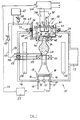
- the device for surface treatment of workpieces shown in Fig. 1 comprises a preferably elongated treatment chamber 11 and an ionization chamber 12 which has a rectangular cross section or a have a cylindrical shape.
- the treatment chamber 11 is designed to be vacuum-tight to the environment and is provided with a connecting piece 13 which is connected to a vacuum pump.
- a plate-shaped anode 15 is arranged above the bottom 14 of the treatment chamber 11.
- the anode 15 is carried by the stand pipes 16 of a cooling fluid line 17, which is designed as a cooling coil 18 within the anode 15.
- the cooling fluid line 17 is led through the bottom 14 of the treatment chamber 11 by means of the sealing elements 19.
- the electrical connecting line 20 between the positive pole of a direct current source 22 and the anode 15 is also passed through a vacuum-tight insulation body 21.
- the negative pole of the DC voltage source 22 is connected via line 23 to the center tap of a transformer, not shown, of an AC voltage source 24. This AC voltage source 24 serves to supply power to the hot cathode 25 in the ionization chamber 12, which is inserted into the cover 26 of the treatment chamber 11.
- the ionization chamber 12 consists of a pot-shaped or trough-shaped housing 27 which projects into the treatment chamber 11 through the opening 28 in the cover 26.
- the peripheral flange 29 of the housing 27 rests on the edge of the opening 28 and is electrically insulated from it and connected to it in a vacuum-tight manner.
- the housing 27 of the ionization chamber 12 is closed in a vacuum-tight manner by means of the cover 30 with the interposition of insulation 31.
- the three electrodes 32, 33 and 34 and an inert gas inlet connection 35 for the noble gas to be ionized in the ionization chamber are passed through the cover 30 of the ionization chamber 12 in a vacuum-tight manner.
- the filaments 36 and 37 are arranged between the two outer electrodes 32 and 34 and the center electrode 33.
- the center electrode 33 is connected to one of the two AC voltage connections of the AC voltage source 24; the other AC voltage connection is connected to the outer electrodes 32 and 34 via the two switches 38, 39.
- the switches 38 and 39 are actuated by a control and monitoring device, not shown, which continuously controls the ohmic resistance of the glow wire 36 which is live when the switch 38 is closed monitors and after reaching a critical, upper value opens the switch 38 and at the same time closes the switch 39 so that current then flows through the second filament 37. It is thereby achieved that in any case, before the first glow wire melts, that is to say with the necessary safety reserve, a switch is made to the second, up to now non-current-carrying glow wire, which then takes over the function of electron emission.
- a control and monitoring device not shown, which continuously controls the ohmic resistance of the glow wire 36 which is live when the switch 38 is closed monitors and after reaching a critical, upper value opens the switch 38 and at the same time closes the switch 39 so that current then flows through the second filament 37. It is thereby achieved that in any case, before the first glow wire melts, that is to say with the necessary safety reserve, a switch is made to the second, up to now non-current-car
- a first magnetic coil 42 is arranged below the bottom 40 of the housing 27, the magnetic field of which constricts the ion current 42 emerging from the ionization chamber 12 in the direction of the opposite anode 15 for the first time.
- the first magnetic coil 42 is cooled by means of a cooling system 44 through which a cooling fluid flows.
- the first magnet coil 42 is connected to a magnet coil power supply 47 via the electrical lines 45 and 46.
- the connecting lines 45 and 46 are led out of the treatment chamber 11 in a vacuum-tight manner through the housing flange 29 of the ionization chamber 12.
- In the connecting line 46 there is a variable resistor 48 in series, with which the current for exciting the magnetic field in the first magnet coil 42 can be adjusted.
- a reactive gas can be introduced into the treatment chamber by means of the tube 49, the mouth 50 of which lies in the vicinity of the opening 41 in the base 40 of the ionization chamber 12.
- a second magnet coil 51 is arranged approximately centrally between the first magnet coil 42 and the anode 15.
- the second magnetic coil 51 is also cooled by means of a cooling system 52.
- the cooling fluid lines 53, the electrical lines 54, 55 for supplying power to the second magnetic coil 51 and the reactive gas line 56 are led through a side wall of the treatment chamber 11 in a vacuum-tight manner.
- the second magnet coil 51 is supplied with power by means of the magnet coil current source 47.
- one connecting line 55 there is an adjusting resistor 57 for the purpose of adjusting the current strength.
- the etching device shown in FIG. 1 is preferably designed as a continuous system.
- the workpieces 58 are arranged parallel to the two side walls of the treatment chamber in their immediate vicinity and thus outside the magnetic field of the first and second magnet coils 42 and 51 and can be passed through the treatment chamber with the aid of transport means, not shown.
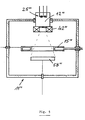
- the device for surface treatment of workpieces shown in FIG. 2 is designed such that two low-voltage arc discharges can take place in it, namely by means of a single ionization chamber 12 ', the structure of which corresponds to that of the ionization chamber 12 according to FIG. 1. In contrast to the latter, this has two ion beam outlet openings 41 ', which are arranged at mutually opposite locations in the wall of the housing 27' of the ionization chamber 12 '.
- each ion beam outlet opening 41 ' there are axially to one another a first magnet coil 42', a second magnet coil 51 'and an anode 15' lying one behind the other in a common plane, so that discharge arcs are located on both sides of the ionization chamber 12 'in the longitudinal direction of the treatment chamber 11' Train 43 '.
- the device according to FIG. 2 is used for the one-sided and full-surface treatment (etching and / or coating) of larger workpieces 59.
- a workpiece 59 the length of which can almost correspond to the length of the treatment chamber 11 '
- a large number of smaller ones can also be used for one-sided treatment Workpieces can be inserted into the chamber 11 '.
- the workpiece 59 can be connected to an auxiliary voltage source 60 or 61, which is arranged outside the treatment chamber 11 '.
- the optional connection to one or the other auxiliary voltage source 60 or 61 takes place via corresponding switches 62 or 63.
- the auxiliary voltage source 60 supplies a high-frequency alternating voltage to the workpiece, while the auxiliary voltage source 61 acts on the workpiece 59 with a direct voltage which is negative relative to the anode potential is designed. If all-round treatment is required, a transport device with a rotatable bracket must be provided.
- Electrode plates 64 are arranged between the discharge arcs 43 'and the nearest wall of the treatment chamber 11' and are cooled by means of a cooling fluid which is fed to the plates 64 via electrically insulated connecting lines 65.
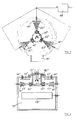
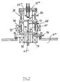
- FIGS. 3 and 4 show an etching device with a cylindrical treatment chamber 11 ′′, in which three radially outwardly extending discharge arches 43 ′′ are produced from a single, centrally arranged ionization chamber 12 ′′, each of which has an angular spacing of 120 ° .
- a magnet coil 42 ′′ and an associated anode 15 ′′ each belong to the generation of the three discharge arcs 43 ′′.
- the voltage supply for all three anodes 15 ′′ comes from a common current source 66.
- the workpieces 58 ′′ are arranged in the cylindrical treatment chamber 11 ′′ below the discharge arches 43 ′′ between them and the bottom of the chamber.
- FIG. 5 shows a further embodiment of the etching device, which is equipped with only a single magnetic coil 42 '' 'directly below the ionization chamber 12' ''.
- the annular, cooled anode 15 '' ' is located approximately in the central plane of the treatment chamber.
- the workpiece 58 '' ' is arranged in the space below the cooled ring anode 15' '' and is connected in an electrically conductive manner to an auxiliary voltage source.
- the ring anode 15 '' ' like the anodes 15 of the devices according to FIGS. 1 to 4, is connected to a voltage source (not shown); it is supplied with a cooling fluid via a fluid line 17 '' '.
- the ionization chamber 12 '' ' is followed by a chamber 67 into which reactive gas is introduced by means of the line 68.
- the reactive gas chamber 67 has an outlet opening 70 for the ion beam in its base 69.
- the cylindrical chamber 67 is on the one hand opposite the ionization chamber 12 '''' and on the other hand by means of the insulating rings 71 and 72 electrically insulated from the treatment chamber 11 ''''.
- Below the chamber 67 and within the treatment chamber 11 '''' is the solenoid 73 which is cooled by means of cooling fluid which is fed via the line 74 to an annular cooling jacket 75 which is arranged on the inside of the solenoid 42 '''' .
- the cylindrical jacket 76 of the chamber 67 is surrounded by a magnet coil 77, which has the function of the magnet coil 42 in FIG. 1.
- the jacket 76 of the chamber 67 can be cooled directly by means of a cooling coil 78 through which cooling fluid flows, which abuts the outer surface, or by direct wall cooling, for example by means of a double wall.
- the housing 27 '' '' of the ionization chamber 12 '' '' can likewise be cooled directly by means of a cooling coil 79 lying on its outer surface, or by direct wall cooling, for example by means of a double wall.
- a noble gas can be introduced into the ionization chamber 12 '' '' via an inlet line 80.
- the arc discharge extends from the ion beam outlet 41 '' '' in the bottom 40 '' '' of the ionization chamber 12 '' '' through the reactive gas chamber 67 and the opening 70 in the bottom 69 thereof into the treatment chamber 11 '' '' the anode, not shown.
- the ionization chamber 12 v and the treatment chamber 11 v essentially correspond to the corresponding contact parts of the treatment device according to FIG. 1.
- a sputtering cathode or a magnetron 81 respectively arranged, which are connected to external power sources 82.
- This device is also suitable as a continuous system, specifically for combined surface treatment using ions from the discharge arc and with atomized material from the atomizing cathodes 81.
Landscapes
- Physics & Mathematics (AREA)
- Engineering & Computer Science (AREA)
- Plasma & Fusion (AREA)
- Chemical & Material Sciences (AREA)
- Analytical Chemistry (AREA)
- ing And Chemical Polishing (AREA)
- Plasma Technology (AREA)
- Grinding Of Cylindrical And Plane Surfaces (AREA)
- Electrical Discharge Machining, Electrochemical Machining, And Combined Machining (AREA)
- Drying Of Semiconductors (AREA)
- Crushing And Grinding (AREA)
Abstract
Description
Die Erfindung betrifft eine Vorrichtung zur Oberflächenbehandlung, insbesondere zum Ätzen und/oder Beschichten von Werkstücken mittels Ionenbeschuß nach dem Oberbegriff des Anspruches 1.The invention relates to a device for surface treatment, in particular for etching and / or coating workpieces by means of ion bombardment according to the preamble of claim 1.
Eine derartige Vorrichtung zur Oberflächenbehandlung, wie beispielsweise zum Ätzen und/oder Beschichten von Werkstücken mittels Ionenbeschuß ist aus der FR-A-2 435 810 bekannt. Diese bekannte Vorrichtung zur Oberflächenbehandlung umfaßt mindestens eine eine Glühkadode umfassende Ionisationskammer, in die Gasatome zur Niedervolt-Bogenentladung zwischen Ionisationskammer und mindestens einer Anode in eine Behandlungskammer eingeleitet werden, die an eine Vakuumpumpe angeschlossen ist. Es ist ferner wenigstens eine Magnetspule vorhanden zur Steuerung der Ionendichte in der Niedervolt-Bogenentladung. Gemäß einer Ausführungsform dieser bekannten Vorrichtung kann wenigtens ein Werkstück seitlich von einem Plasmastrom angeordnet werden, wobei dieser Plasmastrom durch die wenigstens eine Magnetspule gesteuert wird. Diese wenigstens eine Magentspule ist innerhalb der Behandlungskammer angeordnet. Bei dieser bekannten Vorrichtung kann jedoch nur eine Fläche, und zwar die dem Plasmastrom zugewandte Fläche eines Werkstücks oberflächenbehandelt werden, da das Werkstück effektiv nicht vollständig innerhalb der Behandlungskammer angeordnet ist, sondern von außerhalb mit Hilfe einer Werkstückshalterung in einen Behandlungsschacht seitlich in die Kammer eingeführt wird. Dabei befindet sich der eigentliche zu behandelnde Bereich des Werkstücks, nämlich seine vordere Fläche jedoch in radialer Richtung innerhalb der wenigstens einen Magnetspule.Such a device for surface treatment, such as for example for etching and / or coating workpieces by means of ion bombardment, is known from FR-A-2 435 810. This known device for surface treatment comprises at least one ionization chamber comprising a glow plug into which gas atoms for low-voltage arc discharge between the ionization chamber and at least one anode are introduced into a treatment chamber which is connected to a vacuum pump. There is also at least one magnetic coil for controlling the ion density in the low-voltage arc discharge. According to an embodiment of this known device, at least one workpiece can be arranged laterally from a plasma stream, this plasma stream being controlled by the at least one magnetic coil. This at least one magnetic coil is arranged inside the treatment chamber. In this known device, however, only one surface, namely, the surface of a workpiece facing the plasma flow is surface-treated, since the workpiece is effectively not completely arranged within the treatment chamber, but rather is inserted laterally into the treatment chamber from the outside with the aid of a workpiece holder. The actual area of the workpiece to be treated, namely its front surface, is located in the radial direction within the at least one magnet coil.
Aus Patent Abstracts of Japan, Unexamined Applications, E. Field, Band 9, Nr. 136, 12. Juni 1985, The Patent Office Japanese Government, Seite 84 (E-320), Kokai-Nr. 60-20440 und JP-A2-60-20440, ist eine Vorrichtung zur Oberflächenbehandlung bekannt, bei der die Kathode in einer getrennten Ionisationskammer angeordnet ist, wobei sich die Ionisationskammer an eine Behandlungskammer anschließt. Die Ionisationskammer ist gegenüber der Behandlungskammer durch ein Gitter getrennt.From Patent Abstracts of Japan, Unexamined Applications, E. Field, Volume 9, No. 136, June 12, 1985, The Patent Office Japanese Government, page 84 (E-320), Kokai-Nr. 60-20440 and JP-A2-60-20440, a device for surface treatment is known in which the cathode is arranged in a separate ionization chamber, the ionization chamber adjoining a treatment chamber. The ionization chamber is separated from the treatment chamber by a grid.
Die der Erfindung zugrundeliegende Aufgabe besteht darin, eine Vorrichtung zur Oberflächenbehandlung der angegebenen Gattung zu schaffen, welche die Möglichkeit bietet, eine besonders gleichmäßige Oberflächenbehandlung von Werkstücken, und zwar von im wesentlichen der gesamten Werkstückoberfläche, in einem einzigen Arbeitsgang zu erreichen.The object on which the invention is based is to provide a device for surface treatment of the type specified, which offers the possibility of achieving a particularly uniform surface treatment of workpieces, namely of essentially the entire workpiece surface, in a single operation.
Diese Aufgabe wird erfindungsgemäß durch die im Kennzeichnungsteil des Anspruches 1 aufgeführten Merkmale gelöst.This object is achieved by the features listed in the characterizing part of claim 1.
Demnach besteht die Erfindung darin, daß während des Betriebs die zu behandelnden Werkstücke außerhalb des starken Magnetfelds der wenigstens einen Magnetspule in der Behandlungskammer angeordnet sind und daß ferner die Werkstücke derart in der Behandlungskammer angeordnet werden, daß sie eine allseitige Oberflächenbehandlung erfahren.Accordingly, the invention consists in that during operation the workpieces to be treated are arranged outside the strong magnetic field of the at least one magnetic coil in the treatment chamber and that the workpieces are also arranged in the treatment chamber in such a way that that they experience an all-round surface treatment.
Durch diese spezifische Anordnung der Werkstücke befinden sich diese in vorteilhafter Weise praktisch außerhalb des Einflusses der Magnetfelder, welche durch die wenigstens eine Magnetspule erzeugt werden, die zwischen der Glühkathode und der dieser zugeordneten Anode angeordnet ist. Wegen der wandparallelen bzw. entladungsparallelen Anordnung der Werkstücke eignet sich die Vorrichtung nach der Erfindung darüber hinaus auch als Durchlaufanlage.As a result of this specific arrangement of the workpieces, they are advantageously practically outside the influence of the magnetic fields which are generated by the at least one magnetic coil which is arranged between the hot cathode and the anode assigned to it. Because of the wall-parallel or discharge-parallel arrangement of the workpieces, the device according to the invention is also suitable as a continuous system.
Gemäß einer vorteilhaften Ausgestaltung der Erfindung werden mindestens zwei Magnetspulen verwendet, wobei eine erste Magnetspule austrittsseitig an der Ionisationskammer angeordnet ist, während die zweite Magnetspule im wesentlichen mittig zwichen der ersten Magnetspule und der zugehörigen Anode angeordnet ist.According to an advantageous embodiment of the invention, at least two magnet coils are used, a first magnet coil being arranged on the outlet side of the ionization chamber, while the second magnet coil is arranged essentially centrally between the first magnet coil and the associated anode.
Zur gleichzeitigen Behandlung einer Vielzahl von nebeneinander angeordneten Werkstücken bzw. zur Behandlung eines langgestreckten Werkstücks eignet sich besonders eine erfindungsgemäße Vorrichtung, deren Ionisationskammer wenigstens zwei Ionenstrahlaustritte aufweist, denen jeweils eine eigene Anode zugeordnet ist, die dem jeweiligen Ionenstrahlaustritt gegenüberliegt.For the simultaneous treatment of a large number of workpieces arranged next to one another or for the treatment of an elongate workpiece, a device according to the invention is particularly suitable, the ionization chamber of which has at least two ion beam outlets, each of which is assigned its own anode, which is opposite the respective ion beam outlet.
Gemäß einer weiteren vorteilhaften Ausgestaltung der Erfindung ist die Ionisationskammer elektrisch isoliert von der Behandlungskammer angeordnet und besteht aus mindestens zwei Teilen, wobei ein erster Teil die Kühlmittel- und Stromdurchführungen für die Glühkathode enthält, und wobei das zweite Teil die Kühlmittel- und Stromdurchführungen für die Magnetspule umfaßt, die der Ionisationskammer nachgeordnet ist. Direkt anschließend an die Ionenstrahlaustrittsöffnung befindet sich die erste Magnetspule, so daß die Bogenentladung an dieser Stelle stark eingeschnürt und damit die Gasionisation entsprechend aktiviert wird. Durch diese Anordnung läßt sich die benötigte Einschnürung der Bogenentladung mit einem relativ geringen Erregungsstrom für die Spule realisieren.According to a further advantageous embodiment of the invention, the ionization chamber is arranged electrically insulated from the treatment chamber and consists of at least two parts, a first part containing the coolant and current feedthroughs for the hot cathode, and the second part containing the coolant and current feedthroughs for the magnetic coil comprises, which is arranged downstream of the ionization chamber. The first magnetic coil is located directly after the ion beam outlet opening, so that the arc discharge is severely constricted at this point and the gas ionization is activated accordingly. With this arrangement, the required constriction of the arc discharge can be realized with a relatively low excitation current for the coil.
Der Strom innerhalb der Bogenentladung beträgt 100 A und mehr, so daß sowohl die Anode bzw. die Anoden und die vakuumdicht in der Behandlungskammer angeordneten Magnetspulen einer geeigneten Kühlung bedürfen. Zu diesem Zweck werden die Magnetspulen mindestens auf der Wicklungsinnenseite durch einen wassergekühlten Ring gekühlt. Die Anode oder die Anoden sind ebenfalls wassergekühlt, wobei die Kühlfläche auf der Anodenrückseite der Bogenentladung abgewandt vorgesehen ist.The current within the arc discharge is 100 A and more, so that both the anode or the anodes and the magnetic coils arranged in a vacuum-tight manner in the treatment chamber require suitable cooling. For this purpose, the magnetic coils are cooled at least on the inside of the winding by a water-cooled ring. The anode or the anodes are also water-cooled, the cooling surface on the back of the anode being provided facing away from the arc discharge.
Die Ionendichte des Entladungsbogens läßt sich durch Änderung der Magnetfeldstärke einstellen bzw. für eine gleichmäßige Ionenextraktion aus der Gasentladung optimieren. Die Magnetfeldstärke läßt sich entweder durch Variation der die Magnetspulen durchfließenden Ströme oder bzw. und durch eine axiale Verschiebung der Magnetspulen zueinander bzw. zum Plasma der Entladung variieren. Von Vorteil sind dabei Stromquellen für die Magnetspulen mit hoher Ausgangsimpedanz bzw. mit hohem Ausgangswiderstand, so daß induktive Ströme vom Entladungsbogen durch die Wicklungen nicht entstehen können. Während vorzugsweise jede Magnetspule von einer eigenen Stromquelle gespeist wird, ist zur Speisung einer Vielzahl von Anoden eine einzige, gemeinsame Stromquelle vorgesehen.The ion density of the discharge arc can be adjusted by changing the magnetic field strength or optimized for a uniform ion extraction from the gas discharge. The magnetic field strength can be varied either by varying the currents flowing through the magnetic coils or or and by an axial displacement of the magnetic coils relative to one another or to the plasma of the discharge. Current sources for the magnetic coils with a high output impedance or with a high output resistance are advantageous, so that inductive currents from the discharge arc through the windings cannot arise. While each solenoid coil is preferably supplied by its own current source, a single, common current source is provided for supplying a large number of anodes.
Zur gezielten Ionenführung sind die außerhalb des Entladungsbogens und außerhalb des Einflusses der Magnetfelder der Magnetspulen angeordneten Werkstücke vorteilhafterweise an eine regelbare Hilfsspannung anschließbar, wobei diese Hilfsspannung entweder eine hochfrequente Wechselspannung oder eine Gleichspannung ist, die relativ zum Anodenpotential ein negatives Potential aufweist.For targeted ion guidance, the workpieces arranged outside the discharge arc and outside the influence of the magnetic fields of the magnetic coils can advantageously be connected to a controllable auxiliary voltage, this auxiliary voltage being either a high-frequency AC voltage or a DC voltage which has a negative potential relative to the anode potential.
Soll die erfindungsgemäße Vorrichtung als Durchlaufanlage verwendet werden, so kann die Anode oder können die Anoden als wassergekühlte Ringanoden ausgebildet sein und die zu behandelnden Werkstücke werden dann unterhalb dieser Ringanode in der Projektion der Ringöffnung vorbeigeführt.If the device according to the invention is to be used as a continuous system, the anode or the anodes can be designed as water-cooled ring anodes and the workpieces to be treated are then guided past this ring anode in the projection of the ring opening.
Die erfindungsgemäße Vorrichtung ist jedoch nicht nur für das Ätzen von Werkstückoberflächen mittels Beschuß von Edelgasionen vorteilhaft einsetzbar, vielmehr eignet sich die erfindungsgemäße Vorrichtung in vergleichbar vorteilhafter Weise für das sogenannte reaktive Ätzen von Werkstückoberflächen. Bei diesem an sich bekannten Verfahren werden die in der Ionisationskammer erzeugten Edelgasionen außerhalb der Ionisationskammer mit Reaktivgasen zu einem Mischionenstrahl vermischt. Als Reaktivgase eignen sich beispielsweise Sauerstoff und Stickstoff sowie Kohlenstoff, Bor und/oder Fluor enthaltende Gase.However, the device according to the invention can be used advantageously not only for the etching of workpiece surfaces by bombardment of noble gas ions, rather the device according to the invention is suitable in a comparably advantageous manner for the so-called reactive etching of workpiece surfaces. In this method, which is known per se, the noble gas ions generated in the ionization chamber are mixed with reactive gases outside the ionization chamber to form a mixed ion beam. Suitable reactive gases are, for example, oxygen and nitrogen and gases containing carbon, boron and / or fluorine.
Bei der erfindungsgemäßen Vorrichtung ist es vorgesehen, die Reaktivgase oder das Reaktivgasgemisch durch Zuführungsleitungen, die im Innenraum der Magnetspulen münden, in die Behandlungskammer einzuführen, wobei sich die Mündung der Zuführungsleitungen in unmittelbarer Nähe des Ionenstrahls befindet. Bei einer besonders vorteilhaften Ausgestaltung der erfindungsgemäßen Vorrichtung unter Verwendung eines Mischionenstrahls ist eine spezielle Kammer der Ionisationskammer nachgeschaltet, und zwar vorteilhafterweise innerhalb der ersten Magnetspule. Diese Kammer ist mit einem Einlaß für das Reaktivgas versehen.In the device according to the invention, it is provided that the reactive gases or the reactive gas mixture are introduced into the treatment chamber through feed lines which open into the interior of the magnet coils, the mouth of the feed lines being in the immediate vicinity of the ion beam. In a particularly advantageous embodiment of the device according to the invention using a mixed ion beam, a special chamber is connected downstream of the ionization chamber, advantageously within the first magnet coil. This chamber is provided with an inlet for the reactive gas.
Ihr ist eine weitere Magnetspule zugeordnet. Bei dieser Verbundanordnung von Ionisationskammer und Reaktivgaskammer ist der Gasdruck in letzterer niedriger gehalten als in der Ionisationskammer und höher als in der Behandlungskammer. Sollen mehrere Ionenstrahlen erzeugt werden, so kommt eine Vielzahl von solchen Ionisationskammer-Reaktivgaskammer-Einheiten zum Einsatz.Another magnetic coil is assigned to it. In this composite arrangement of ionization chamber and reactive gas chamber, the gas pressure in the latter is kept lower than in the ionization chamber and higher than in the treatment chamber. If several ion beams are to be generated, a large number of such ionization chamber-reactive gas chamber units are used.
Bei Verwendung dieser Verbundkammern läuft die Gasionisierung in zwei Phasen ab, wobei in der ersten Phase ein Edelgas, wie beispielsweise Argon, Helium oder Neon kontinuierlich in die Ionisationskammer eingeleitet und dort ionisiert wird. Die Ionen, welche die Ionisationskammer über die Lochblende zur Reaktivgaskammer hin verlassen, werden mit Hilfe der ersten Magnetspule in ihrer Dichte konzentriert und vermischen sich in der Reaktivgaskammer mit den in diese Kammer kontinuierlich eingeführten Gasen, die in einer zweiten Ionisierungsphase ionisiet werden. Eine weitere Einschnürung des Plasmas erfolgt durch die Lochblende der Reaktivgaskammer hinter dieser Lochblende mit Hilfe einer weiteren, zweiten Magnetspule. Die Einstellung der Drücke innerhalb der Kammern erfolgt durch entsprechende Wahl der Öffnungsdurchmesser der Lochblenden und durch Einstellung des Edel- und Reaktivggaspartialdruckes, und zwar unter Berücksichtigung des Saugvermögens der Vakuumpumpe, an die die Behandlungskammer angeschlossen ist.When using these composite chambers, the gas ionization takes place in two phases, a noble gas, such as argon, helium or neon, being continuously introduced into the ionization chamber in the first phase and ionized there. The ions that leave the ionization chamber via the pinhole to the reactive gas chamber are concentrated in their density with the aid of the first magnetic coil and mix in the reactive gas chamber with the gases continuously introduced into this chamber, which are ionized in a second ionization phase. A further constriction of the plasma takes place through the pinhole of the reactive gas chamber behind this pinhole with the help of a further, second magnetic coil. The pressures within the chambers are set by appropriately selecting the opening diameters of the orifice plates and by adjusting the noble and reactive gas partial pressures, taking into account the suction capacity of the vacuum pump to which the treatment chamber is connected.
Vorteilhafterweise ist die Reaktivgaskammer elektrisch isoliert zur Ionisationskammer angeordnet und die beiden Kammern sind auf Schwebepotential gehalten.The reactive gas chamber is advantageously arranged electrically insulated from the ionization chamber and the two chambers are kept at floating potential.
Die Vorteile der der Ionisationskammer nachgeschalteten Kammer bestehen darin, daß die Ionisationskammer selbst frei von Reaktivgasen ist, so daß die Glühkathode nicht einem Beschuß mit Reaktivgasionen ausgesetzt ist und damit eine höhere Lebensdauer hat als bei entsprechenden Vorrichtungen gemäß dem Stand der Technik. Außerdem kann der Edelgasdruck in der Ionisationskammer bei Nachschaltung einer Reaktivgaskammer verringert werden, was wiederum die Lebensdauer der Glühkathode positiv beeinflußt. Weiterhin kann der Anteil an ionisierten Gasatomen dadurch wesentlich erhöht werden, daß das Reaktivgas unittelbar in den Bereich der höchsten Ionendichte des Entladungsbogens sowie der höchsten Magnetfeldstärke eingeführt wird. Zudem kann das Verhältnis zwischen Edelgas- und Reaktivgaspartialdrücken auf diese Weise frei eingestellt werden, so daß die übliche Abhängigkeit zwischen den Entladungsparametern, wie beispielsweise der Druck in der Ionisationskammer, Bogenstrom, Anodenspannung und Magnetfeldstärke und den Ätzparametern, wie beispielsweiese der Druck in der Behandlungskammer, Werkstückvorspannung und Ionenstrom zu den Werkstücken, fast vollständig beseitigt ist.The advantages of the chamber downstream of the ionization chamber are that the ionization chamber itself is free of reactive gases, so that the hot cathode is not exposed to bombardment with reactive gas ions and thus has a longer service life than with corresponding devices according to the prior art. In addition, the noble gas pressure in the ionization chamber can be reduced when a reactive gas chamber is connected, which in turn has a positive effect on the life of the hot cathode. Furthermore, the proportion of ionized gas atoms can be significant be increased so that the reactive gas is introduced directly into the region of the highest ion density of the discharge arc and the highest magnetic field strength. In addition, the ratio between rare gas and reactive gas partial pressures can be freely set in this way, so that the usual dependency between the discharge parameters, such as the pressure in the ionization chamber, arc current, anode voltage and magnetic field strength, and the etching parameters, such as the pressure in the treatment chamber, Workpiece preload and ion current to the workpieces is almost completely eliminated.
Die vorteilhaften Anwendungsmöglichkeiten der erfindungsgemäß ausgebildeten Vorrichtung werden noch dadurch ergänzt, daß unter Beibehaltung der bereits beschriebenen Vorteile die Beschichtung von Werkstücken aus der Gasphase möglich ist.The advantageous possible uses of the device designed according to the invention are supplemented by the fact that the workpieces can be coated from the gas phase while maintaining the advantages already described.
Auf diese Weise können z.B. Schichten aus Bornitrit oder Borkarbid auf den Werkstückoberflächen hergestellt werden, indem Bor und Stickstoff bzw. Kohlenstoff enthaltende Gase verwendet werden. Ebenso können diamantähnliche Schichten, sogenannte i-C-Schichten, auf die Werkstücke aufgebracht werden, wenn eine Kohlenwasserstoffverbindung als Reaktivgas verwendet wird.In this way e.g. Layers of boron nitride or boron carbide are produced on the workpiece surfaces by using gases containing boron and nitrogen or carbon. Likewise, diamond-like layers, so-called i-C layers, can be applied to the workpieces if a hydrocarbon compound is used as the reactive gas.
Zusätzlich kann der Entladungsbogen als Ionenquelle für die Zerstäubung von Atomen aus einer Kathode aus festem Material verwendet werden, wobei die unter Ionenbeschuß sich befindende Kathodenoberfläche aus dem zu zerstäubenden Material besteht. Die Kathode wird auf einem gegenüber der Anode der Bogenentladung negativen Potential gehalten, und an die zu behandelnden Werkstücke ist eine hochfrequente Wechselspannung oder eine gegenüber der Anode negative Spannung gelegt, so daß die Ablagerung der Ionen und neutralen Teilchen auf die Werkstückoberflächen möglich ist.In addition, the discharge arc can be used as an ion source for atomizing atoms from a cathode made of solid material, the cathode surface under ion bombardment consisting of the material to be atomized. The cathode is kept at a negative potential with respect to the anode of the arc discharge, and a high-frequency alternating voltage or a negative voltage with respect to the anode is applied to the workpieces to be treated, so that the deposition of the ions and neutral particles on the workpiece surfaces is possible.
Alternativ hierzu kann der Entladungsbogen als Elektronenquelle für die Verdampfung von festen Materialien verwendet werden, wobei das zu verdampfende Material selbst als Anode der Bogenentladung dient. An die zu behandelnden Werkstücke ist wiederum hochfrequente Wechselspannung oder gegenüber der Anode der Bogenspannung negative Gleichspannung angelegt, so daß die Ablagerung der Ionen und neutralen Teilchen auf den Werkstückoberflächen möglich ist.Alternatively, the discharge arc can be used as an electron source for the evaporation of solid materials, the material to be evaporated itself serving as the anode for the arc discharge. In turn, high-frequency AC voltage or negative DC voltage with respect to the anode of the arc voltage is applied to the workpieces to be treated, so that the deposition of the ions and neutral particles on the workpiece surfaces is possible.
Mit Hilfe der erfindungsgemäßen Vorrichtung lassen sich auch metallische Schichten, nämlich aus dem Kathodenmaterial oder aus Verdampfungsprodukten, auf den Werkstückoberflächen aufbringen, die sich mit anderen Materialien, wie beispielsweise Reaktivgasen verbinden. Dadurch ergeben sich Schichten von beispielsweise Nitriden, Oxiden, Karbiden oder Boriden auf der Werkstückoberfläche. Es lassen sich also metallische Schichten mit Einlagerungen von anderen Materialien realisieren. Diese stammen beispielsweise aus der Ionisation in der Reaktivgaskammer oder aus der Ringöffnung der Magnetspulen.With the aid of the device according to the invention, metallic layers, namely from the cathode material or from evaporation products, can also be applied to the workpiece surfaces, which combine with other materials, such as reactive gases. This results in layers of, for example, nitrides, oxides, carbides or borides on the workpiece surface. Metallic layers with inclusions of other materials can thus be realized. These originate, for example, from ionization in the reactive gas chamber or from the ring opening of the magnetic coils.
Gemäß einer weiteren Ausführungsform der erfindungsgemäßen Vorrichtung sind auch die elektrisch isoliert von der Behandlungskammer angeordneten Gehäuse der Magnetspulen auf Schwebepotential gehalten.According to a further embodiment of the device according to the invention, the housings of the magnetic coils, which are arranged electrically insulated from the treatment chamber, are also kept at floating potential.
Zur Erhöhung der Glühkathoden-Lebensdauer ist es erfindungsgemäß vorgesehen, die Glühkathode aus einer Wechselspannungsquelle und die Anode aus einer Gleichspannungsquelle mit Strom zu versorgen, wobei der negative Ausgang der Gleichstromquelle an ein Spannungsmittenpotential der Wechselspannungsquelle angeschlossen ist, vor allem an die sekundärseitige Mittenanzapfung eines Transformators der Wechselspannungsquelle, der sekundärseitig den Strom für die Glühkathode liefert.To increase the life of the hot cathode, it is provided according to the invention to supply the hot cathode with an AC voltage source and the anode with a DC voltage source, the negative output of the DC power source being connected to a voltage center potential of the AC voltage source, especially to the secondary center tap of a transformer AC voltage source that supplies the current for the hot cathode on the secondary side.
Um einen kontinuierlichen Betrieb mit optimaler Elektronenemission zu gewährleisten, besteht die Glühkathode aus drei über Glühdrähte miteinander verbundene Elektroden, wobei die Mittenelektrode ständig und die beiden Außenelektroden wechselweise über Schalter an die Wechselspannungsquelle angeschlossen bzw. anschließbar sind. Im Betrieb ist jeweils vorzugsweise einer der Glühdrähte über ein Paar von Elektroden an die Spannungsquelle angeschlossen und der Widerstandswert dieses Glühdrahtes wird kontinuierlich mittels einer Widerstandsmeßeinrichtung überwacht, die bei Überschreiten eines vorbestimmten Widerstandsgrenzwertes dieses Glühdrahts die Wechselspannungsquelle auf den benachbarten Glühdraht umschaltet, bevor ein Durchschmelzen des ersten Glühdrahts erfolgt. Dadurch ist ein jederzeit sicherer Betrieb der erfindungsgemäßen Vorrichtung gewährleistet.In order to ensure continuous operation with optimal electron emission, the hot cathode consists of three electrodes which are connected to one another by means of filaments, the center electrode and the two outer electrodes being connected or connectable to the AC voltage source alternately via switches. In operation, one of the filaments is preferably connected to the voltage source via a pair of electrodes, and the resistance value of this filament is continuously monitored by means of a resistance measuring device which, when a predetermined resistance limit value of this filament is exceeded, switches the AC voltage source to the adjacent filament before the first one melts Glow wire is done. This ensures safe operation of the device according to the invention at all times.
Um bei einseitiger Anordnung der Werkstücke gegenüber dem Ionenstrahl eine bevorzugte Richtung der Teilchenbewegung zu erzwingen, können Hilfselektroden in die Behandlungskammer eingebracht werden, die die Funktion von elektrischen Abschirmungen übernehmen. Übermäßiges Erhitzen der nahe am Entladungsbogen angebrachten Hilfselektroden läßt sich durch eine Kühlung dieser Elektroden vermeiden.In order to force a preferred direction of particle movement when the workpieces are arranged on one side with respect to the ion beam, auxiliary electrodes can be introduced into the treatment chamber, which act as electrical shields. Excessive heating of the auxiliary electrodes located close to the discharge arc can be avoided by cooling these electrodes.
Der Gegenstand der Erfindung ist in den Fig. 1 bis 7 der Zeichnung anhand mehrerer bevorzugter Ausführungsbeipsiele dargestellt, welche nachstehend im einzelnen näher beschrieben sind. Es zeigen:
- Fig. 1
- einen Axialschnitt durch die erfindungsgemäß ausgebildete Vorrichtung längs des einzigen Entladungsbogens;
- Fig. 2
- einen Längsschnitt durch eine erfindungsgemäß ausgebildete Vorrichtung mit zwei Entladungsbögen;
- Fig. 3
- eine Aufsicht auf eine erfindungsgemäß ausgebildete Vorrichtung mit drei Entladungsbögen in deren Mittenebene;
- Fig. 4
- einen Axialschnitt entlang der Linien IV-IV in Fig. 3;
- Fig. 5
- einen Schnitt durch eine Vorrichtung einer weiteren Ausführungsform;
- Fig. 6
- einen Schnitt durch eine Ionisationskammer und Reaktivgaskammer der erfindungsgemäß ausgebildeten Vorrichtungen, und
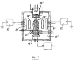
- Fig. 7
- einen Schnitt durch eine Vorrichtung zum kombinierten Ätzen und Beschichten von Werkstücken in einer weiteren Ausführungsform.
- Fig. 1
- an axial section through the device designed according to the invention along the single discharge arc;
- Fig. 2
- a longitudinal section through a device designed according to the invention with two discharge arches;
- Fig. 3
- a top view of a device designed according to the invention with three discharge arcs in the central plane thereof;
- Fig. 4
- an axial section along the lines IV-IV in Fig. 3;
- Fig. 5
- a section through a device of a further embodiment;
- Fig. 6
- a section through an ionization chamber and reactive gas chamber of the devices designed according to the invention, and
- Fig. 7
- a section through a device for combined etching and coating of workpieces in a further embodiment.
Die in Fig. 1 dargestellte Vorrichtung zur Oberflächenbehandlung von Werkstücken umfaßt eine vorzugsweise langgestreckte Behandlungskammer 11 sowie eine Ionisationskammer 12, die einen rechteckigen Querschnitt oder eine zylindrische Form aufweisen. Die Behandlungskammer 11 ist vakuumdicht gegen die Umgebung ausgelegt und mit einem Anschlußstutzen 13 versehen, der an eine Vakuumpumpe angeschlossen ist.The device for surface treatment of workpieces shown in Fig. 1 comprises a preferably elongated
Oberhalb des Bodens 14 der Behandlungskammer 11 ist eine plattenförmige Anode 15 angeordnet. Die Anode 15 wird von den Standrohren 16 einer Kühlfluidleitung 17 getragen, welche innerhalb der Anode 15 als Kühlschlange 18 ausgebildet ist. Die Kühlfluidleitung 17 ist mittels der Dichtungselemente 19 durch den Boden 14 der Behandlungskammer 11 hindurchgeführt. Auch die elektrische Verbindungsleitung 20 zwischen dem Pluspol einer Gleichstromquelle 22 und der Anode 15 ist durch einen vakuumdichten Isolationskörper 21 hindurchgeführt. Der Minuspol der Gleichspannungsquelle 22 ist über die Leitung 23 mit dem Mittelabgriff eines nicht dargestellten Transformators einer Wechselspannungsquelle 24 verbunden. Diese Wechselspannungsquelle 24 dient der Stromversorgung der Glühkathode 25 in der Ionisationskammer 12, welche in den Deckel 26 der Behandlungskammer 11 eingesetzt ist.A plate-shaped
Die Ionisationskammer 12 besteht aus einem topf- oder wannenförmigen Gehäuse 27, das durch die Öffnung 28 im Deckel 26 der Behandlungskammer 11 in diese hineinragt. Der periphere Flansch 29 des Gehäuses 27 liegt auf dem Rand der Öffnung 28 auf und ist diesem gegenüber elektrisch isoliert und mit diesem vakuumdicht verbunden.The
Das Gehäuse 27 der Ionisationskammer 12 ist mittels des Deckels 30 unter Zwischenlage einer Isolierung 31 vakuumdicht verschlossen. Durch den Deckel 30 der Ionisationskammer 12 sind die drei Elektroden 32, 33 und 34 sowie ein Edelgaseinlaßstutzen 35 für das in der Ionisationskammer zu ionisierende Edelgas vakuumdicht hindurchgeführt. Zwischen den beiden äußeren Elektroden 32 und 34 und der Mittenelektrode 33 sind die Glühdrähte 36 und 37 angeordnet. Die Mittenelektrode 33 ist mit einem der beiden Wechselspannungsanschlüsse der Wechselspannungsquelle 24 verbunden; der andere Wechselspannungsanschluß ist über die beiden Schalter 38, 39 mit den äußeren Elektroden 32 bzw. 34 verbunden. Die Schalter 38 und 39 werden von einer nicht dargestellten Steuer- und Überwachungseinrichtung betätigt, welche den Ohm'schen Widerstand des bei geschlossenem Schalter 38 stromführenden Glühdrahts 36 kontinuierlich überwacht und nach Erreichen eines kritischen, oberen Wertes den Schalter 38 öffnet und gleichzeitig den Schalter 39 schließt, damit dann der zweite Glühdraht 37 von Strom durchflossen wird. Dadurch wird erreicht, daß in jedem Fall vor einem Durchschmelzen des ersten Glühdrahts, d.h. also mit der notwendigen Sicherheitsreserve, auf den zweiten, bislang nicht stromführenden Glühdraht umgeschaltet wird, der dann die Funktion der Elektronenemission übernimmt. Im Boden 40 des Gehäuses 27 befindet sich zentrisch eine Ionenstrahlaustrittöffnung 41 bzw. eine Lochblende, über welche die Ionisationskammer 12 mit der Behandlungskammer 11 verbunden ist. Unterhalb des Bodens 40 des Gehäuses 27 ist eine erste Magnetspule 42 angeordnet, deren Magnetfeld den aus der Ionisationskammer 12 in Richtung auf die gegenüberliegende Anode 15 austretenden Ionenstrom 42 ein erstes Mal einschnürt. Die erste Magnetspule 42 wird mittels eines von einem Kühlfluid durchströmten Kühlsystems 44 gekühlt. Die erste Magnetspule 42 ist über die elektrischen Leitungen 45 und 46 an eine Magnetspulen-Stromversorgung 47 angeschlossen. Die Anschlußleitungen 45 und 46 sind vakuumdicht durch den Gehäuseflansch 29 der Ionisationskammer 12 aus der Behandlungskammer 11 herausgeführt. In der Anschlußleitung 46 befindet sich in Reihe ein Stellwiderstand 48, mit dem der Strom zur Erregung des Magnetfeldes in der ersten Magnetspule 42 einstellbar ist. Mittels des Rohres 49, dessen Mündung 50 in der Nahe der Öffnung 41 im Boden 40 der Ionisationskammer 12 liegt, ist ein Reaktivgas in die Behandlungskammer einführbar.The
Zwecks weiterer Einschnürung des Ionenstroms bzw. zur Steuerung der Ionendichte im Mittenbereich des Entladungsbogens 43 ist eine zweite Magnetspule 51 etwa mittig zwischen der ersten Magnetspule 42 und der Anode 15 angeordnet. Auch die zweite Magnetspule 51 wird mittels eines Kühlsystems 52 gekühlt. Die Kühlfluidleitungen 53, die elektrischen Leitungen 54, 55 zur Stromversorgung der zweiten Magnetspule 51 und die Reaktivgasleitung 56 sind vakuumdicht durch eine Seitenwand der Behandlungskammer 11 hindurchgeführt. Die Stromversorgung der zweiten Magnetspule 51 erfolgt mittels der Magnetspulen-Stromquelle 47. In der einen Verbindungsleitung 55 befindet sich ein Stellwiderstand 57 zwecks Einstellung der Stromstärke.For the purpose of further constricting the ion current or for controlling the ion density in the central region of the
Die in Fig. 1 dargestellte Ätzvorrichtung ist vorzugsweise als Durchlaufanlage ausgelegt. Die Werkstücke 58 sind parallel zu den beiden Seitenwänden der Behandlungskammer in deren unmittelbarer Nähe und damit außerhalb des Magnetfeldes der ersten und der zweiten Magnetspule 42 und 51 angeordnet und können mit Hilfe nicht dargestellter Transportmittel durch die Behandlungskammer hindurchgeführt werden.The etching device shown in FIG. 1 is preferably designed as a continuous system. The
Die in Fig. 2 dargestellte Vorrichtung zur Oberflächenbehandlung von Werkstücken ist derart ausgebildet, daß in ihr zwei Niedervolt-Bogenentladungen stattfinden können, und zwar mittels einer einzigen Ionisationskammer 12', deren Aufbau der Ionisationskammer 12 nach Fig. 1 entspricht. Im Gegensatz zu letzterer weist diese zwei Ionenstrahlaustrittsöffnungen 41' auf, die an einander gegenübergelegenen Stellen in der Wandung des Gehäuses 27' der Ionisationskammer 12' angeordnet sind. Hinter einer jeden Ionenstrahlaustrittsöffnung 41' befinden sich axial zu diesen in einer gemeinsamen Ebene hintereinanderliegend eine erste Magnetspule 42' sowie eine zweite Magnetspule 51' und eine Anode 15', so daß sich beidseitig der Ionisationskammer 12' in der Längsrichtung der Behandlungskammer 11' liegende Entladungsbögen 43' ausbilden.The device for surface treatment of workpieces shown in FIG. 2 is designed such that two low-voltage arc discharges can take place in it, namely by means of a single ionization chamber 12 ', the structure of which corresponds to that of the
Die Vorrichtung gemäß Fig. 2 dient der einseitigen und vollflächigen Behandlung (Ätzen und bzw. oder Beschichten) größerer Werkstücke 59. Anstelle eines Werkstücks 59, dessen Länge knapp der Länge der Behandlungskammer 11' entsprechen kann, kann zur einseitigen Behandlung auch eine Vielzahl von kleineren Werkstücken in die Kammer 11' eingesetzt sein. Das Werkstück 59 ist an eine Hilfsspannungsquelle 60 oder 61 anschließbar, die außerhalb der Behandlungskammer 11' angeordnet ist. Der wahlweise Anschluß an die eine oder die andere Hilfsspannungsquelle 60 oder 61 erfolgt über entsprechende Schalter 62 bzw. 63. Die Hilfsspannungsquelle 60 liefert eine hochfrequente Wechselspannung an das Werkstück, während die Hilfsspannungsquelle 61 das Werkstück 59 mit einer Gleichspannung beaufschlagt, die relativ zum Anodenpotential negativ ausgelegt ist. Falls allseitige Behandlung gewünscht ist, ist eine Transporteinrichtung mit drehbarer Halterung vorzusehen.The device according to FIG. 2 is used for the one-sided and full-surface treatment (etching and / or coating) of
Zwischen den Entladungsbögen 43' und der nächstgelegenen Wandung der Behandlungskammer 11' sind Elektrodenplatten 64 angeordnet, welche mittels eines Kühlfluids gekühlt werden, das Ober elektrisch isolierte Anschlußleitungen 65 den Platten 64 zugeführt wird.
In den Figuren 3 und 4 ist eine Ätzvorrichtung mit einer zylindrischen Behandlungskammer 11'' dargestellt, bei welcher aus einer einzigen zentrisch angeordneten Ionisationskammer 12'' drei sich radial nach außen erstreckende Entladungsbögen 43'' erzeugt werden, die einen Winkelabstand von je 120° haben. Zur Erzeugung der drei Entladungsbögen 43'' gehört jeweils eine Magnetspule 42'' und eine zugeordnete Anode 15''. Die spannungsversorgung für alle drei Anoden 15'' erfolgt aus einer gemeinsamen Stromquelle 66.FIGS. 3 and 4 show an etching device with a
Wie aus Fig. 4 hervorgeht, sind die Werkstücke 58'' in der zylindrischen Behandlungskammer 11'' unterhalb der Entladungsbögen 43'' zwischen diesen und dem Boden der Kammer angeordnet.As can be seen from FIG. 4, the
In Fig. 5 ist eine weitere Ausführungsform der Ätzvorrichtung dargestellt, die mit nur einer einzigen Magnetspule 42''' direkt unterhalb der Ionisationskammer 12''' ausgerüstet ist. Die ringförmige, gekühlte Anode 15''' befindet sich in etwa in der Mittelebene der Behandlungskammer. Das Werkstück 58''' ist in dem Raum unterhalb der gekühlten Ringanode 15''' angeordnet und elektisch leitend mit einer Hilfsspannungsquelle verbunden. Die Ringanode 15''' ist ebenso wie die Anoden 15 der Vorrichtungen nach den Figuren 1 bis 4 an eine nicht dargestellte Spannungsquelle angeschlossen; ihr wird über eine Fluidleitung 17''' ein Kühlfluid zugeführt.5 shows a further embodiment of the etching device, which is equipped with only a single magnetic coil 42 '' 'directly below the ionization chamber 12' ''. The annular, cooled anode 15 '' 'is located approximately in the central plane of the treatment chamber. The workpiece 58 '' 'is arranged in the space below the cooled ring anode 15' '' and is connected in an electrically conductive manner to an auxiliary voltage source. The ring anode 15 '' ', like the
Bei der Ausführungsform nach Fig. 6 ist der Ionisationskammer 12''' eine Kammer 67 nachgeschaltet, in die mittels der Leitung 68 Reaktivgas eingleitet wird.In the embodiment according to FIG. 6, the ionization chamber 12 '' 'is followed by a
Die Reaktivgaskammer 67 weist in ihrem boden 69 eine Austrittsöffnung 70 für den Ionenstrahl auf. Die zylindrische Kammer 67 ist mittels der Isolierringe 71 und 72 einerseits gegenüber der Ionisationskammer 12'''' und andererseits gegenüber der Behandlungskammer 11'''' elektrisch isoliert. Unterhalb der Kammer 67 und innerhalb der Behandlungskammer 11'''' befindet sich die Magnetspule 73, die mittels Kühlfluid gekühlt wird, das über die Leitung 74 einem ringförmigen Kühlmantel 75 zugeführt wird, welcher auf der Innenseite der Magnetspule 42'''' angeordnet ist.The
Den zylindrischen Mantel 76 der Kammer 67 umgibt eine Magnetspule 77, welcher die Funktion der Magnetspule 42 in Fig. 1 zukommt. Der Mantel 76 der Kammer 67 kann mittels einer von Kühlfluid durchströmten Kühlschlange 78 direkt gekühlt werden, die an der Außenfläche anliegt, oder durch direkte Wandkühlung, beispielsweise mittels einer Doppelwandung.The
Das Gehäuse 27'''' der Ionisationskammer 12'''' kann gleichfalls mittels einer an deren Außenfläche anliegenden Kühlschlange 79 direkt gekühlt werden, oder durch direkte Wandkühlung, beispielsweise mittels einer Doppelwandung. Weiterhin kann in die Ionisationskammer 12'''' über eine Einlaßleitung 80 ein Edelgas eingeleitet werden. Die Bogenentladung erstreckt sich von dem Ionenstrahlaustritt 41'''' im boden 40'''' der Ionisationskammer 12'''' durch die Reaktivgaskammer 67 und die Öffnung 70 in deren Boden 69 hindurch in die Behandlungskammer 11'''' hinein bis zu der nicht dargestellten Anode.The housing 27 '' '' of the ionization chamber 12 '' '' can likewise be cooled directly by means of a cooling
Bei dem Ausführungsbeispiel nach Fig. 7 entsprechen die Ionisationskammer 12v und die Behandlungskammer 11v im wesentlichen den entsprechenden Anlageteilen der Behandlungsvorrichtung nach Fig. 1. Zwischen den Werkstücken 58v und den Seitenwänden der Behandlungskammer 11v ist jeweils eine Zerstäubungskathode bzw. ein Magnetron 81 angeordnet, die an externe Stromquellen 82 angeschlossen sind. Diese Vorrichtung eignet sich ebenfalls als Durchlaufanlage, und zwar zur kombinierten Oberflächenbehandlung mittels Ionen aus dem Entladungsbogen sowie mit zerstäubtem Material von den Zerstäubungskathoden 81.In the exemplary embodiment according to FIG. 7, the
Claims (17)
- Apparatus for surface treatment, in particular for etching and/or coating workpieces (58) by means of ion bombardment, the apparatus having at least one ionisation chamber (12) surrounding a glow cathode (25), in which ionisation chamber (12) gas atoms for low-voltage arc discharge between the ionisation chamber (12) and at least one anode (15) are introduced into the treatment chamber (11) which is connected to a vacuum pump, and at least one magnetic coil (42, 52, 73) for controlling ion density in the low-voltage arc discharge, with the workpieces (58) being arranged on the side of a plasma current which is controlled by the at least one magnetic coil (42, 51, 73) and with the at least one magnetic coil being arranged within the treatment chamber (11), characterised in thata) during operation, the workpieces (58) to be treated are arranged radially outside the strong magnetic field of the at least one magnetic coil (42, 51, 73) in the treatment chamber (11) andb) the workpieces are arranged in the treatment chamber (11) such that they undergo surface treatment on all sides.
- Apparatus according to claim 1, characterised by an arrangement of magnetic coils (42, 51, 73) in the region of the arc discharge between the glow cathode (25) and the anode (15), wherein the magnetic coil axes coincide substantially with the arc discharge central axis.
- Apparatus according to claim 1 or 2, characterised in that the workpieces (58) are arranged in the vicinity of the wall or of the walls of the treatment chamber (11).
- Apparatus according to one of claims 1 to 3, characterised by a first magnetic coil (42), which is arranged in the direction of the anode (15) directly behind the ion beam outlet opening (41) in the housing (27) of the ionisation chamber (12) and at least one second magnetic coil (51) which is arranged between the first magnetic coil (42) and the anode (15).
- Apparatus according to one of claims 1 to 4, characterised by an ionisation chamber (12) with at least two ion beam outlet openings (41), each of which is arranged axially opposed to an anode (15).
- Apparatus according to one of claims 1 to 5, characterised in that the magnetic coils (42, 51, 73) are arranged in an axially displaceable manner.
- Apparatus according to one of claims 1 to 6, characterised in that the current sources (47) for the magnetic coils (42, 51, 73) have a high output impedance and that their current strength is able to be controlled.
- Apparatus according to one of claims 1 to 7, characterised by the connection of a controllable auxiliary voltage to the workpieces to be treated (58).
- Apparatus according to claim 8, characterised in that the auxiliary voltage is a high-frequency alternating voltage.
- Apparatus according to claim 8, characterised in that the auxiliary voltage is a negative direct voltage relative to the anode potential.
- Apparatus according to one of claims 1 to 10, characterised in that the anode (15) is formed as a water-cooled annular anode (15''') and the workpieces (58''') are arranged in the direction of movement of the ion beam (42''') below or behind the annular anode (15''') (Figure 5).
- Apparatus according to one of claims 1 to 11, having an arrangement for introducing a reactive gas or a reactive gas mixture into the treatment chamber (11), characterised in that the supply lines (49, 56) for the reactive gas open into the inner chamber of the magnetic coils (42, 51).
- Apparatus according to claim 12, characterised in that the reactive gas supply line (49) to the inner chamber of the first magnetic coil (42) opens in the immediate vicinity of the ion beam outlet opening (41) of the ionisation chamber (12).
- Apparatus according to one or more of claims 1 to 11, characterised by a reactive gas chamber (67), connected after the ionisation chamber (12) and surrounded by a first magnetic coil (77), the chamber having an inlet line (68) for the reactive gas, and by a second magnetic coil in the region of a mixed ion beam outlet opening (70), with the gas pressure in the reactive gas chamber (67) being kept lower than in the ionisation chamber (12) and higher than in the treatment chamber (11).
- Apparatus according to one of claims 1 to 14 characterised by an alternating current supply part (24) for the glow cathode (25) and a direct current supply part (22) for the anode (15), with the negative output of the direct-current supply part (22) being connected to a voltage average potential of the alternating current supply part (24) for the glow cathode (25), in particular to the secondary side central tapping of a transformer of this part.
- Apparatus according to claim 15, characterised in that the glow cathode (25) comprises three electrodes (32, 33, 34) connected with each other by way of glow wires (36, 37), with the central electrode (33) being connected or able to be connected permanently to the alternating current supply part (24) and the two outer electrodes (32 and 34) being connected or able to be connected to the alternating current supply part (24) alternately by way of switches (38, 39).
- Apparatus according to claim 16, characterised by a measuring and control device activating the two connecting switches (38, 39) in dependence on the high ohmic resistance of the glow wires (36, 37), which, when a predetermined resistance boundary value of the glow wire carrying current is exceeded, opens the connection switch of the associated outer electrode and closes the connection switch of the other outer electrode.
Priority Applications (1)
| Application Number | Priority Date | Filing Date | Title |
|---|---|---|---|
| AT87106534T ATE102395T1 (en) | 1986-05-06 | 1987-05-06 | DEVICE FOR SURFACE TREATMENT OF WORKPIECES. |
Applications Claiming Priority (2)
| Application Number | Priority Date | Filing Date | Title |
|---|---|---|---|
| DE3615361 | 1986-05-06 | ||
| DE3615361A DE3615361C2 (en) | 1986-05-06 | 1986-05-06 | Device for the surface treatment of workpieces |
Publications (3)
| Publication Number | Publication Date |
|---|---|
| EP0247397A2 EP0247397A2 (en) | 1987-12-02 |
| EP0247397A3 EP0247397A3 (en) | 1989-02-01 |
| EP0247397B1 true EP0247397B1 (en) | 1994-03-02 |
Family
ID=6300298
Family Applications (1)
| Application Number | Title | Priority Date | Filing Date |
|---|---|---|---|
| EP87106534A Expired - Lifetime EP0247397B1 (en) | 1986-05-06 | 1987-05-06 | Apparatus for the surface treatment of work pieces |
Country Status (4)
| Country | Link |
|---|---|
| US (1) | US4769101A (en) |
| EP (1) | EP0247397B1 (en) |
| AT (1) | ATE102395T1 (en) |
| DE (2) | DE3615361C2 (en) |
Families Citing this family (20)
| Publication number | Priority date | Publication date | Assignee | Title |
|---|---|---|---|---|
| US4952273A (en) * | 1988-09-21 | 1990-08-28 | Microscience, Inc. | Plasma generation in electron cyclotron resonance |
| US5032205A (en) * | 1989-05-05 | 1991-07-16 | Wisconsin Alumni Research Foundation | Plasma etching apparatus with surface magnetic fields |
| US5052331A (en) * | 1989-10-18 | 1991-10-01 | The United States Of America As Represented By The United Sates Department Of Energy | Apparatus for gas-metal arc deposition |
| CA2065581C (en) | 1991-04-22 | 2002-03-12 | Andal Corp. | Plasma enhancement apparatus and method for physical vapor deposition |
| CH687111A5 (en) * | 1992-05-26 | 1996-09-13 | Balzers Hochvakuum | A method for generating a low voltage discharge, vacuum treatment system here, as well as for application of the method. |
| US5374801A (en) * | 1993-11-15 | 1994-12-20 | The United States Of America As Represented By The Administrator Of The National Aeronautics And Space Administration | Plasma heating for containerless and microgravity materials processing |
| DE19538045C1 (en) * | 1995-10-13 | 1997-01-30 | Forschungszentrum Juelich Gmbh | Device for coating substrates |
| DE19725930C2 (en) * | 1997-06-16 | 2002-07-18 | Eberhard Moll Gmbh Dr | Process and system for treating substrates using ions from a low-voltage arc discharge |
| WO2000036631A1 (en) * | 1998-12-11 | 2000-06-22 | Surface Technology Systems Limited | Plasma processing apparatus |
| FR2799920B1 (en) * | 1999-10-19 | 2002-01-11 | Metal Process | PROCESS FOR PRODUCING A PLASMA BY DISTRIBUTED DISCHARGES OF CAPACITIVE TYPE, AND DEVICE FOR CARRYING OUT SUCH A PROCESS |
| DE10010126C2 (en) * | 2000-03-03 | 2002-10-10 | Cobes Gmbh Nachrichten Und Dat | Method and device for plasma treatment of the surface of substrates by ion bombardment |
| US20020185226A1 (en) * | 2000-08-10 | 2002-12-12 | Lea Leslie Michael | Plasma processing apparatus |
| DE10335470A1 (en) * | 2003-08-02 | 2005-02-24 | Fraunhofer-Gesellschaft zur Förderung der angewandten Forschung e.V. | Method and device for coating or modifying surfaces |
| US20070135769A1 (en) * | 2005-12-09 | 2007-06-14 | Tollini Dennis R | Device and method for supporting a medical device |
| US8802545B2 (en) * | 2011-03-14 | 2014-08-12 | Plasma-Therm Llc | Method and apparatus for plasma dicing a semi-conductor wafer |
| DE102012024340A1 (en) * | 2012-12-13 | 2014-06-18 | Oerlikon Trading Ag, Trübbach | plasma source |
| WO2014182333A1 (en) * | 2013-05-09 | 2014-11-13 | Fomani Arash Akhavan | Vacuum pumps for producing adsorbate-free surfaces |
| DE102015101294A1 (en) * | 2015-01-29 | 2016-08-04 | Fraunhofer-Gesellschaft zur Förderung der angewandten Forschung e.V. | Apparatus for generating a hollow cathode arc discharge plasma |
| US10629417B1 (en) * | 2016-12-01 | 2020-04-21 | ColdQuanta, Inc. | Sputter ion pump with penning-trap current sensor |
| CN108231529B (en) * | 2018-03-09 | 2024-04-05 | 晓睿真空设备(嘉兴)有限公司 | Low-voltage magnetic control cathode ion source |
Family Cites Families (12)
| Publication number | Priority date | Publication date | Assignee | Title |
|---|---|---|---|---|
| CA941781A (en) * | 1970-05-13 | 1974-02-12 | United Aircraft Corporation | Metal deposition by liquid phase sputtering |
| CH551498A (en) * | 1972-05-09 | 1974-07-15 | Balzers Patent Beteilig Ag | ARRANGEMENT FOR COLLECTING SUBSTANCES ON DOCUMENTS BY MEANS OF AN ELECTRIC LOW VOLTAGE DISCHARGE. |
| JPS51117933A (en) * | 1975-04-10 | 1976-10-16 | Tokuda Seisakusho | Spattering apparatus |
| JPS5275341A (en) * | 1975-12-19 | 1977-06-24 | Rikagaku Kenkyusho | Method of producing echelette grating |
| DE2625870A1 (en) * | 1976-06-09 | 1977-12-22 | Siemens Ag | Photo-lithographical etching process - for semiconductor devices preceded by specified ion bombardment to clean all conductor track windows |
| CH631743A5 (en) * | 1977-06-01 | 1982-08-31 | Balzers Hochvakuum | METHOD FOR EVAPORATING MATERIAL IN A VACUUM EVAPORATION SYSTEM. |
| CH633729A5 (en) * | 1978-01-04 | 1982-12-31 | Georgy Alexandrovich Kovalsky | Device for coating products |
| JPS54110988A (en) * | 1978-01-31 | 1979-08-30 | Nii Chiefunorogii Afutomobirin | Coating vacuum evaporation apparatus |
| FR2435810A1 (en) * | 1978-09-08 | 1980-04-04 | Anvar | Sputtering appts. to improve deposit purity - avoids line of sight of electron discharge and uses non-polluting material, typically stainless steel, for structural purposes |
| CH645137A5 (en) * | 1981-03-13 | 1984-09-14 | Balzers Hochvakuum | METHOD AND DEVICE FOR EVAPORATING MATERIAL UNDER VACUUM. |
| JPS57202732A (en) * | 1981-06-05 | 1982-12-11 | Mitsubishi Electric Corp | Fine pattern formation |
| US4486287A (en) * | 1984-02-06 | 1984-12-04 | Fournier Paul R | Cross-field diode sputtering target assembly |
-
1986
- 1986-05-06 DE DE3615361A patent/DE3615361C2/en not_active Expired - Fee Related
-
1987
- 1987-05-05 US US07/046,119 patent/US4769101A/en not_active Expired - Fee Related
- 1987-05-06 EP EP87106534A patent/EP0247397B1/en not_active Expired - Lifetime
- 1987-05-06 DE DE87106534T patent/DE3789163D1/en not_active Expired - Lifetime
- 1987-05-06 AT AT87106534T patent/ATE102395T1/en active
Also Published As
| Publication number | Publication date |
|---|---|
| DE3615361C2 (en) | 1994-09-01 |
| EP0247397A2 (en) | 1987-12-02 |
| DE3789163D1 (en) | 1994-04-07 |
| ATE102395T1 (en) | 1994-03-15 |
| DE3615361A1 (en) | 1987-11-12 |
| EP0247397A3 (en) | 1989-02-01 |
| US4769101A (en) | 1988-09-06 |
Similar Documents
| Publication | Publication Date | Title |
|---|---|---|
| EP0247397B1 (en) | Apparatus for the surface treatment of work pieces | |
| DE69224483T2 (en) | PLASMA BURNER, ESPECIALLY FOR CHEMICAL PROCESSES | |
| DE19853943B4 (en) | Cathode for sputtering or arc vapor deposition as well as apparatus for coating or ion implantation with such a cathode | |
| DE69019741T2 (en) | ION RAY CANNON. | |
| EP0489239B1 (en) | Sputtering apparatus with magnetron cathodes for coating of substrates | |
| EP2849204B1 (en) | Plasma generating apparatus | |
| DE69421157T2 (en) | Plasma jet generation method and apparatus which can generate a high power plasma jet | |
| SE450539B (en) | PLASMA PACKAGING FOR PLANNING TRANSFERS | |
| DE69112166T2 (en) | Plasma source device for ion implantation. | |
| DE2255483C2 (en) | Device for heating gases by means of an electric arc | |
| DE3689232T2 (en) | Ion source. | |
| DE3330144C2 (en) | Method for uniform heating of material to be heated in a vacuum recipient | |
| EP2030490B1 (en) | Method and apparatus for generating a plasma and use of the same | |
| US20080264341A1 (en) | Apparatus for cathodic vacuum-arc coating deposition | |
| DE1188221B (en) | Process for generating an energy-rich, high-temperature gas discharge | |
| DE4333825C1 (en) | Apparatus for coating elongated flexible products | |
| DE19753684C1 (en) | Device for treating workpieces in a low-pressure plasma | |
| DE2527609C3 (en) | Ion source | |
| DE2434830A1 (en) | ELECTRON BEAM SYSTEM FOR THERMAL PROCESSING OF OBJECTS BY ELECTRON Bombardment | |
| DE3303677C2 (en) | Plasma cannon | |
| EP0484704A1 (en) | Low voltage arc discharge and variable magnetic field for heating a substrate | |
| DE102008028166B4 (en) | Apparatus for generating a plasma jet | |
| EP1593142B1 (en) | Magnetically enhanced plasma processing installation for continuous material | |
| DE1240199B (en) | Discharge device for generating a high-energy arc discharge | |
| DE2228117A1 (en) | HOLLOW CATHODE DUOPLASMATRON ION SOURCE |
Legal Events
| Date | Code | Title | Description |
|---|---|---|---|
| PUAI | Public reference made under article 153(3) epc to a published international application that has entered the european phase |
Free format text: ORIGINAL CODE: 0009012 |
|
| AK | Designated contracting states |
Kind code of ref document: A2 Designated state(s): AT BE CH DE ES FR GB GR IT LI LU NL SE |
|
| RBV | Designated contracting states (corrected) |
Designated state(s): AT BE CH DE ES FR GB IT LI NL SE |
|
| PUAL | Search report despatched |
Free format text: ORIGINAL CODE: 0009013 |
|
| AK | Designated contracting states |
Kind code of ref document: A3 Designated state(s): AT BE CH DE ES FR GB IT LI NL SE |
|
| 17P | Request for examination filed |
Effective date: 19890711 |
|
| 17Q | First examination report despatched |
Effective date: 19910429 |
|
| GRAA | (expected) grant |
Free format text: ORIGINAL CODE: 0009210 |
|
| AK | Designated contracting states |
Kind code of ref document: B1 Designated state(s): AT BE CH DE ES FR GB IT LI NL SE |
|
| PG25 | Lapsed in a contracting state [announced via postgrant information from national office to epo] |
Ref country code: SE Free format text: THE PATENT HAS BEEN ANNULLED BY A DECISION OF A NATIONAL AUTHORITY Effective date: 19940302 Ref country code: GB Effective date: 19940302 Ref country code: BE Effective date: 19940302 |
|
| REF | Corresponds to: |
Ref document number: 102395 Country of ref document: AT Date of ref document: 19940315 Kind code of ref document: T |
|
| REF | Corresponds to: |
Ref document number: 3789163 Country of ref document: DE Date of ref document: 19940407 |
|
| ITTA | It: last paid annual fee | ||
| ITF | It: translation for a ep patent filed | ||
| PG25 | Lapsed in a contracting state [announced via postgrant information from national office to epo] |
Ref country code: ES Free format text: LAPSE BECAUSE OF FAILURE TO SUBMIT A TRANSLATION OF THE DESCRIPTION OR TO PAY THE FEE WITHIN THE PRESCRIBED TIME-LIMIT Effective date: 19940613 |
|
| ET | Fr: translation filed | ||
| GBV | Gb: ep patent (uk) treated as always having been void in accordance with gb section 77(7)/1977 [no translation filed] |
Effective date: 19940302 |
|
| PLBE | No opposition filed within time limit |
Free format text: ORIGINAL CODE: 0009261 |
|
| STAA | Information on the status of an ep patent application or granted ep patent |
Free format text: STATUS: NO OPPOSITION FILED WITHIN TIME LIMIT |
|
| 26N | No opposition filed | ||
| PG25 | Lapsed in a contracting state [announced via postgrant information from national office to epo] |
Ref country code: FR Free format text: LAPSE BECAUSE OF NON-PAYMENT OF DUE FEES Effective date: 19980130 |
|
| REG | Reference to a national code |
Ref country code: FR Ref legal event code: ST |
|
| PGFP | Annual fee paid to national office [announced via postgrant information from national office to epo] |
Ref country code: FR Payment date: 19980422 Year of fee payment: 12 |
|
| PGFP | Annual fee paid to national office [announced via postgrant information from national office to epo] |
Ref country code: AT Payment date: 19981117 Year of fee payment: 12 |
|
| PG25 | Lapsed in a contracting state [announced via postgrant information from national office to epo] |
Ref country code: AT Free format text: LAPSE BECAUSE OF NON-PAYMENT OF DUE FEES Effective date: 19990506 |
|
| PGFP | Annual fee paid to national office [announced via postgrant information from national office to epo] |
Ref country code: NL Payment date: 20010508 Year of fee payment: 15 |
|
| PGFP | Annual fee paid to national office [announced via postgrant information from national office to epo] |
Ref country code: CH Payment date: 20010509 Year of fee payment: 15 |
|
| PG25 | Lapsed in a contracting state [announced via postgrant information from national office to epo] |
Ref country code: LI Free format text: LAPSE BECAUSE OF NON-PAYMENT OF DUE FEES Effective date: 20020531 Ref country code: CH Free format text: LAPSE BECAUSE OF NON-PAYMENT OF DUE FEES Effective date: 20020531 |
|
| PG25 | Lapsed in a contracting state [announced via postgrant information from national office to epo] |
Ref country code: NL Free format text: LAPSE BECAUSE OF NON-PAYMENT OF DUE FEES Effective date: 20021201 |
|
| REG | Reference to a national code |
Ref country code: CH Ref legal event code: PL |
|
| NLV4 | Nl: lapsed or anulled due to non-payment of the annual fee |
Effective date: 20021201 |
|
| PG25 | Lapsed in a contracting state [announced via postgrant information from national office to epo] |
Ref country code: IT Free format text: LAPSE BECAUSE OF NON-PAYMENT OF DUE FEES;WARNING: LAPSES OF ITALIAN PATENTS WITH EFFECTIVE DATE BEFORE 2007 MAY HAVE OCCURRED AT ANY TIME BEFORE 2007. THE CORRECT EFFECTIVE DATE MAY BE DIFFERENT FROM THE ONE RECORDED. Effective date: 20050506 |
|
| PGFP | Annual fee paid to national office [announced via postgrant information from national office to epo] |
Ref country code: DE Payment date: 20060523 Year of fee payment: 20 |