EP0647752B1 - Serrure débrayable pour véhicules et similaires - Google Patents
Serrure débrayable pour véhicules et similaires Download PDFInfo
- Publication number
- EP0647752B1 EP0647752B1 EP19940500162 EP94500162A EP0647752B1 EP 0647752 B1 EP0647752 B1 EP 0647752B1 EP 19940500162 EP19940500162 EP 19940500162 EP 94500162 A EP94500162 A EP 94500162A EP 0647752 B1 EP0647752 B1 EP 0647752B1
- Authority
- EP
- European Patent Office
- Prior art keywords
- rotor
- lock
- piece
- coupling
- rotation
- Prior art date
- Legal status (The legal status is an assumption and is not a legal conclusion. Google has not performed a legal analysis and makes no representation as to the accuracy of the status listed.)
- Expired - Lifetime
Links
- 230000008878 coupling Effects 0.000 claims description 62
- 238000010168 coupling process Methods 0.000 claims description 62
- 238000005859 coupling reaction Methods 0.000 claims description 62
- 230000005540 biological transmission Effects 0.000 claims description 44
- 230000000295 complement effect Effects 0.000 claims description 14
- 230000000694 effects Effects 0.000 claims description 3
- 230000037431 insertion Effects 0.000 claims 1
- 238000003780 insertion Methods 0.000 claims 1
- 230000000903 blocking effect Effects 0.000 description 7
- 238000006073 displacement reaction Methods 0.000 description 6
- 238000004519 manufacturing process Methods 0.000 description 3
- 238000013459 approach Methods 0.000 description 1
- 230000015556 catabolic process Effects 0.000 description 1
- 230000006355 external stress Effects 0.000 description 1
- 238000000605 extraction Methods 0.000 description 1
- 230000013011 mating Effects 0.000 description 1
- 238000000034 method Methods 0.000 description 1
- 230000035882 stress Effects 0.000 description 1
Images


Classifications
-
- E—FIXED CONSTRUCTIONS
- E05—LOCKS; KEYS; WINDOW OR DOOR FITTINGS; SAFES
- E05B—LOCKS; ACCESSORIES THEREFOR; HANDCUFFS
- E05B17/00—Accessories in connection with locks
- E05B17/04—Devices for coupling the turning cylinder of a single or a double cylinder lock with the bolt operating member
-
- E—FIXED CONSTRUCTIONS
- E05—LOCKS; KEYS; WINDOW OR DOOR FITTINGS; SAFES
- E05B—LOCKS; ACCESSORIES THEREFOR; HANDCUFFS
- E05B17/00—Accessories in connection with locks
- E05B17/0054—Fraction or shear lines; Slip-clutches, resilient parts or the like for preventing damage when forced or slammed
- E05B17/0058—Fraction or shear lines; Slip-clutches, resilient parts or the like for preventing damage when forced or slammed with non-destructive disengagement
Definitions
- the present invention relates to a lock detachable for motor vehicles and the like type which includes a rotor fitted with glitter mounted roundabout inside a stator, and a socket fitted roundabout between the rotor and the stator, said socket being provided with grooves allowing the passage of said glitter.
- the lock head is not operated only when a correct key is inserted into the lock, because in this case the rotor moves axially, and remains coupled in rotation with said head; if we introduce a false key or any other type object, the rotor turns but it does not move axially, and therefore does not act on the latch head.
- Patent application DE-A-4122414 describes a lock disengageable in which a sleeve interposed between rotor and stator comprises means for moving axially and cause a clutch when trying to force the lock.
- Document FR-A-2635351 discloses a releasable lock with the features of the preamble of claim 1.
- the disengageable lock for motor vehicles and the like according to the present invention is defined in claim 1.
- the rotor and latch head are usually integral in rotation, so that does not occur no clutch release operation when opening or closing with the correct key; the lock is released only when try to open with any tool or a fake key. Logically, this results in a decrease in the stresses on the moving parts of the lock, and therefore longer useful life.
- the user does not need apply a force to insert the key into the lock, which does not increase the convenience of use.
- the rotor and the sleeve do not move axially; so we even avoid the possibility of forcing the lock by applying a torque of torsion to the rotor and pushing at the same time with a axial force preventing displacement of the sleeve.
- the socket assembly is advantageously consisting of two identical half-sockets, substantially shaped semi-cylindrical.
- This embodiment of the socket facilitates its manufacturing, while reducing complexity and bulk of the mold, and allowing larger series of manufacturing; in addition, it simplifies the assembly process of the lock.
- means for moving axial of the coupling part when its rotation include at least one longitudinal coupling of the coupling piece with the stator, the walls of which are inclined, and the transmission part cooperates with the locking head through at least one coupling longitudinal.
- the union between the transmission part and the rotor is constituted an axial projection of the rotor of non-circular section mates with a complementary axial notch practiced in the transmission room.
- the union between the room coupling and the socket consists of at least one longitudinal projection of the housed coupling piece in a complementary longitudinal notch practiced in the socket.
- the coupling piece rotates with the socket and can also move relative to it.
- Another feature of this achievement consists of the said means so that the part coupling drives the transmission part in its axial movement have a transverse shoulder consisting of the coupling piece, which mates with another complementary transverse shoulder made up by the transmission part.
- the transmission part and the coupling piece are elastically linked; in this case, the transmission part can be at least partially made of a flexible material, and said means for the coupling piece to drive the piece in its axial movement have a flexible longitudinal tongue formed on the workpiece transmission and provided with a transverse shoulder, said shoulder coupling with another transverse shoulder complementary formed in the coupling part.
- the transmission part and the coupling part can therefore be mounted by elasticity one with the other.
- said front head may be integral with the rotor, the two elements can constitute a single piece.
- lock has latching means of the latch head, actuated by effect of the element axially movable as it passes from said first position at said second position.
- latching means it becomes impossible to violate the lock by acting directly in the lock, for example through the groove in the body for the vehicle window, because a correct key not being inserted in the lock, movement of the latch causes the action of the latching means and the lock lock.
- Said latching means include a blocking element in the form of a C, consisting of a body and two wings, which body is housed, at least partially in a longitudinal groove in the surface inside of the stator and the two wings protrude from the stator in the radial direction and towards the inside of the lock, and in that one of the wings of the blocking element is driven by a protrusion of the rotor when producing the axial movement of it, and as a result of that displacement, the other wing is introduced into a housing practiced in the latch head, so that said head is secured in rotation to the stator, and by therefore locked.
- a blocking element in the form of a C, consisting of a body and two wings, which body is housed, at least partially in a longitudinal groove in the surface inside of the stator and the two wings protrude from the stator in the radial direction and towards the inside of the lock, and in that one of the wings of the blocking element is driven by a protrusion of the rotor when producing the axial movement of
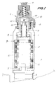
- a releasable lock comprises, as will be appreciated for example in FIG. 1, a stator 1 and a rotor 2, provided with known form of guards or glitter 3, and that is likely to turn in the stator when, insert the appropriate key into the lock, the glitter 3 remains level with the surface of the rotor and they do not remain protruding.
- the rotor has not been shown in section in the figures.
- the socket 4 consists of two half-sockets identical, in order to reduce the manufacturing cost and simplify assembly.
- the lock also has a front head 5, through which the key is introduced, and which is fitted as usual with a retractable hatch (not shown) to protect the inside of the lock.
- the rotor 2 is linked in rotation to a latch head 6 which in turn supports a lock 7, the rotation causes the lock to open.
- the latch head 6 has two elements 61 (exterior) and 62 (interior), which are integral with the by means of a pin 63.
- the union of the rotor with the latch head is such that it allows axial movement of the rotor, between a rotational coupling position with the head latch holder (engaged position) and a position where the two parts become uncoupled (disengaged position): when the rotor moves axially towards the position disengaged, the rotation of the rotor is not transmitted to the lock.
- the rotor is moves to said position when it is rotated with an object other than the correct key.
- the coupling between rotor 2 and element 62 of the latch head can be formed by notches longitudinal A: the rotor carries parts in protrusions that are introduced into housing complementary to element 62.
- a coil spring 9 is located inside of element 62 of the latch head, so that it remains placed around the rotor 2; he is supported by one of its ends against a rim of the own element 62 and by the other end against a removable mounted part 10 at the end of the rotor.
- spring 9 The purpose of spring 9 is to maintain the rotor 2 in the engaged position.
- the rotor 2 and the head front 5 form two separate parts: when the rotor is in the engaged position (shown in the figure 1), there remains a space 11 between the rotor and the head frontal; however, in order to keep the union rotating in between, which can be best seen in the figure 3, a longitudinal coupling has been planned, consisting here by a projection 5c of the front head, with a housing complementary 2c in the rotor, and a projection 2d of the rotor, with additional 5d housing in the head frontal.
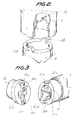
- the frontal head is provided with two 5th projections, in correspondence with 4th notches on the socket 4.
- the socket 4 is mounted inside the stator, so that if you rotate the socket, the union with the stator forces it to move axially.
- the socket has two protrusions at one end longitudinal 4b, which are usually (in position disengaged) housed in corresponding cavities 1b of the stator.
- the projections 4b and the cavities 1b are shaped with corresponding inclined planes, as it stands shown in the figure, so that if we rotate the socket relative to the stator, on the socket acts a axial force component due to the inclined planes of mating, which involves moving the socket 4, which moves away from the latch head 6 and approaches the front head 5.
- the rotor 2 is integral in rotation with the head lock holder thanks to coupling A, which means that the lock is engaged.
- the glitter 3 does not go back inside the rotor, but they protrude and pass through the grooves of the socket 4.
- the rotor and bush can stay in an angular position such as the lock remains disengaged, with the sleeve and the rotor in its position axial closest to the frontal head.
- the glitter will go in removal, uncoupling the rotor from the bushing, which could cause the key to turn the rotor, but without succeeding in returning the socket to its initial position.
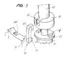
- the rotor 102 and the sleeve 104 are also roundabouts, however not being axially mobile; the lock has an integral transmission part 120 in rotation of the rotor 102 but being able to move axially, and a coupling piece 140 integral in rotation of the socket but which can move axially.
- the coupling piece 140 shown in perspective in FIG. 5, is provided with longitudinal projections 140b, similar to projections 4b on the socket from the previous embodiment ( Figure 2), which are housed normally in the cavities 1b of the stator, and which move the part 140 when it is caused to rotate.
- the part 140 is provided with legs 140f, which form means for securing in rotation the part 140 of the sleeve 104, which allows relative axial displacement.
- the socket 104 has housings 104f complementary legs 140f.
- the transmission part 120 is coupled in rotation with the rotor thanks to an axial coupling with square section, formed by a 120h housing of the room transmission and a 102h projection of the rotor, and it cooperates with the lock head of a shape similar to that of coupling A of the previous embodiment.
- rotor 2 was split into rotor 102 (more short and axially fixed) and a transmission part 120 likely to be moved
- socket 4 has been split into a socket 104 (shorter and axially fixed) and a coupling piece 140 capable of being moved.
- the coupling piece 140 When the coupling piece 140 moves axially, it drives with this displacement the part of transmission 120, thanks to the existence of a rung 140i, 120i between the two rooms.
- the piece transmission 120 is driven in the axial direction by the coupling part, thereby disengaging the coupling part transmission in relation to the lock head, since the two parts of coupling A move apart.
- Rotor and sleeve rotate without offering resistance, but the latch head remains stationary, and the lock cannot be opened.
- This feature allows the front head 105 is fixed relative to the rotor; if we desire, the two elements can be integral, being able even constitute a single piece.
- the coin coupling carries two radial projections 140g (figure 5) which, when the coupling piece moves axially, are introduced into housings complementary (not shown) practiced in the surface outside of rotor 102: if the lock is disengaged when the user enters a correct key, the rotor rotates the coupling piece 140 through these 140g projections, until the projections 140b carried by said part 140 are in correspondence of its complementary cavities 1b of the stator and the lock is engaged again.
- FIG. 6 shows a variant of the realization of the invention, similarly based on the existence of a transmission part, here in terms plastic, between the rotor and the latch head, and a coupling piece between said transmission piece and the socket.
- a transmission part here in terms plastic
- the lock head 206 is shorter, and the transmission piece 220 cooperates with the head through a coupling A similar to that described in previous achievements.
- the coupling piece 240 in turn has a union with the stator similar to the coupling B of previous achievements (here, 240b with 1b), moving so axially when it is rotated, and legs 240f which cooperate with housings 204f carried by socket 204.
- the rotor 202 and sleeve 204 are not moved axially, but the declutching takes place between the transmission part and the latch head 206.
- the coupling piece is provided, so to drive the transmission part in an axial direction, a transverse shoulder 240i, which cooperates with a flexible longitudinal tongue 220i, in turn provided with a transverse shoulder of the transmission part.
- the mounting between the two parts is carried out by deformation elastic tongue 220i.
- the lock is completed with a washer 13 and a rivet 14, intended to hold the assembled assembly.
- Spring 9 pushes transmission piece 220 towards the lock holder head 206 in order to hold the lock normally engaged.
- the socket When using the appropriate wrench, the socket remains at rest, and the rotation is transmitted from the rotor to the transmission part and from this to the lock holder head.
- the glitter drives the socket with the rotor; in turn, the socket drives the part coupling, which is therefore moved in the direction axial and drives the transmission part.
- the moving the transmission part causes its uncoupling of the lock head, which remains so at rest.
- the lock operates in a manner substantially analogous to that of the described embodiment referring to Figures 4 and 5; the configuration of the elements is, however, different, in order to reduce the size longitudinal of the lock.
- Figures 7 and 8 show two different operating positions of the lock Figure 1, therefore corresponding to the known embodiment described.
- stator 1 in the inner surface of stator 1, we practiced a longitudinal groove 50, inside which is housed at least the body 71 of a blocking element 70 or latching, further provided with two wings 72 and 73, of so that it has the shape of a C.
- the lock is mounted and in the position normal clutch, shown in figure 8, the element blocking 70 remains disposed with the wing 73 below a circumferential projection 21 of the rotor 2, and with the wing 72 above a circumferential projection 90 of the inner element 62 of the latch head 6.
- FIG. 7 shows the position different elements when the lock is disengaged, either by an attempt to rotate the rotor with a element different from a correct key, either by an attempt to turn the lock directly.
- the socket 4 rotates, and moves axially by driving the rotor 2.
- the projection 21 drives then the wing 73 of the blocking element and, this one also moves.
- the wing 72 is introduced into the housing 91 of the latch head.
- the blocking element also being housed in the groove 50 of the stator as in the housing 91 of the latch head, these two pieces cannot be rotated mutual; therefore, the lock remains blocked.
- the rotor and the sleeve rotate freely.
- the lock holder head first turns a small angle, insufficient to open the door, and drives with it the rotor because they are secured in rotation (clutch engaged); the rotor, however, drives its turn the socket, because in the absence of a key the glitter make the two rotating parts integral, and thanks to the inclined planes described in the known embodiment, the sleeve moves towards the front part of the lock driving the rotor. This, in turn, moves the blocking element, which causes latching of the latch head relative to the stator, and therefore the latch head cannot turn.
- this declutching also comprising the actuation of means of latching head which remains blocked with the stator.
Landscapes
- Lock And Its Accessories (AREA)
- Vehicle Cleaning, Maintenance, Repair, Refitting, And Outriggers (AREA)
Applications Claiming Priority (2)
| Application Number | Priority Date | Filing Date | Title |
|---|---|---|---|
| ES9302184 | 1993-10-08 | ||
| ES9302184A ES2073369B1 (es) | 1993-10-08 | 1993-10-08 | Cerradura desembragable para vehiculos y similares. |
Publications (3)
| Publication Number | Publication Date |
|---|---|
| EP0647752A2 EP0647752A2 (fr) | 1995-04-12 |
| EP0647752A3 EP0647752A3 (fr) | 1996-05-01 |
| EP0647752B1 true EP0647752B1 (fr) | 1999-03-31 |
Family
ID=8283353
Family Applications (1)
| Application Number | Title | Priority Date | Filing Date |
|---|---|---|---|
| EP19940500162 Expired - Lifetime EP0647752B1 (fr) | 1993-10-08 | 1994-10-05 | Serrure débrayable pour véhicules et similaires |
Country Status (3)
| Country | Link |
|---|---|
| EP (1) | EP0647752B1 (https=) |
| DE (1) | DE69417499T2 (https=) |
| ES (1) | ES2073369B1 (https=) |
Families Citing this family (14)
| Publication number | Priority date | Publication date | Assignee | Title |
|---|---|---|---|---|
| FR2740163B1 (fr) * | 1995-10-18 | 1997-11-21 | Valeo Securite Habitacle | Verrou du type a rotor debrayable |
| FR2748513B1 (fr) * | 1996-05-10 | 1998-06-26 | Valeo Securite Habitacle | Verrou a debrayage axial pour un mecanisme de serrure de vehicule automobile |
| US5991117A (en) * | 1996-05-14 | 1999-11-23 | Storage Technology Corporation One Storage Tek Drive | Break away lever for a tape drive handle |
| FR2776325B1 (fr) * | 1998-03-17 | 2000-04-28 | Valeo Securite Habitacle | Verrou a debrayage axial perfectionne pour un mecanisme de serrure de vehicule automobile |
| GB2350146A (en) * | 1999-05-13 | 2000-11-22 | Rover Group | Motor vehicle lock assembly |
| DE19939261A1 (de) * | 1999-08-19 | 2001-02-22 | Bremicker Soehne Kg A | Schloß mit Zylinderschutz |
| IT1310740B1 (it) * | 1999-11-26 | 2002-02-22 | Giobert Spa | Serratura a cilindro con dispositivo di sicurezza. |
| DE10346956B3 (de) * | 2003-10-09 | 2005-04-21 | Daimlerchrysler Ag | Schließzylinder für ein Schloss, insbesondere bei Fahrzeugen |
| FR2895762A1 (fr) * | 2005-12-30 | 2007-07-06 | Valeo Securite Habitacle Sas | Verrou debrayable pour un mecanisme de serrure automobile |
| DE102009050381A1 (de) * | 2009-10-22 | 2011-04-28 | Huf Hülsbeck & Fürst Gmbh & Co. Kg | Schließzylinder |
| DE102009052406A1 (de) | 2009-11-10 | 2011-05-12 | Huf Hülsbeck & Fürst Gmbh & Co. Kg | Schließzylinder |
| DE102011001055A1 (de) * | 2010-10-08 | 2012-04-12 | Huf Hülsbeck & Fürst Gmbh & Co. Kg | Schließzylinder |
| ITTO20110192A1 (it) * | 2011-03-03 | 2012-09-04 | Giobert Spa | Serratura provvista di un sistema anti-effrazione per una porta di un veicolo |
| CN208073175U (zh) * | 2018-02-08 | 2018-11-09 | 长园共创电力安全技术股份有限公司 | 轴向式离合解闭锁机构的连接结构 |
Family Cites Families (4)
| Publication number | Priority date | Publication date | Assignee | Title |
|---|---|---|---|---|
| JPS6237473A (ja) * | 1985-08-08 | 1987-02-18 | 太田 富夫 | シリンダ−錠 |
| FR2631067B1 (fr) * | 1988-05-04 | 1991-02-08 | Neiman Sa | Verrou a rotor debrayable |
| DE3827418A1 (de) * | 1988-08-12 | 1990-02-15 | Daimler Benz Ag | Schliesszylinder |
| DE4122414C1 (de) * | 1991-07-06 | 1992-12-03 | Huelsbeck & Fuerst | Schließzylinder |
-
1993
- 1993-10-08 ES ES9302184A patent/ES2073369B1/es not_active Expired - Fee Related
-
1994
- 1994-10-05 DE DE1994617499 patent/DE69417499T2/de not_active Expired - Fee Related
- 1994-10-05 EP EP19940500162 patent/EP0647752B1/fr not_active Expired - Lifetime
Also Published As
| Publication number | Publication date |
|---|---|
| ES2073369A2 (es) | 1995-08-01 |
| ES2073369R (https=) | 1998-04-01 |
| DE69417499T2 (de) | 1999-09-23 |
| EP0647752A2 (fr) | 1995-04-12 |
| ES2073369B1 (es) | 1999-06-16 |
| DE69417499D1 (de) | 1999-05-06 |
| EP0647752A3 (fr) | 1996-05-01 |
Similar Documents
| Publication | Publication Date | Title |
|---|---|---|
| EP0806531B1 (fr) | Verrou à débrayage axial pour un mécanisme de serrure de véhicule automobile | |
| EP0647752B1 (fr) | Serrure débrayable pour véhicules et similaires | |
| EP1084915B1 (fr) | Antivol de direction de véhicule automobile | |
| EP3718429B1 (fr) | Insert pour un bracelet de montre | |
| EP2082282A1 (fr) | Element de charniere elastique a grande amplitude pour monture de lunettes | |
| FR2964350A1 (fr) | Antivol de direction pour vehicule automobile | |
| EP2201200B1 (fr) | Cle pivotante a blocage en position renforce, pour l'actionnement d'une serrure | |
| EP0943758B1 (fr) | Verrou à débrayage axial perfectionné pour un mécanisme de serrure de véhicule automobile | |
| EP1126108B1 (fr) | Organe de rétention pour serrure de véhicule automobile, son procédé de fabrication, et serrure comportant un tel organe de rétention | |
| EP0140740B1 (fr) | Serrure de sûreté | |
| EP1859113A1 (fr) | Verrou debrayable pour un mecanisme de serrure automobile | |
| EP1863986B1 (fr) | Verrou debrayable pour un mecanisme de serrure automobile | |
| EP1580358A1 (fr) | Protection pour dispositif d'entrainement pour l'actionnement d'une serrure par un verrou | |
| FR2614921A1 (fr) | Dispositif de securite a l'arrachement et a l'enfoncement d'une piece emmanchee dans une autre piece, et ensemble formant serrure de surete equipe de ce dispositif | |
| EP0234144B1 (fr) | Serrure de sûreté à clé, notamment pour véhicule automobile | |
| CH645812A5 (en) | Ski safety binding | |
| EP2079629A2 (fr) | Dispositif de fixation d'un premier sous-ensemble sur un second sous- ensemble de véhicule automobile. | |
| EP1449993A1 (fr) | Poignée de véhicule automobile comportant des moyens élastiques de blocage d'un élément externe. | |
| EP1927710B1 (fr) | Verrou débrayable notamment pour mécanisme de serrure de véhicule automobile | |
| FR2752863A1 (fr) | Procede pour le codage d'un verrou a disques rotatifs et verrou code selon un tel procede | |
| EP4091018A1 (fr) | Charniere en matiere plastique | |
| FR2552146A1 (fr) | Serrure de surete | |
| FR2775716A1 (fr) | Cylindre de surete a barillet double | |
| FR2667897A1 (fr) | Dispositif a tige permettant une lente rotation. | |
| EP0869236B1 (fr) | Cylindre de sûrete manoeuvrable d'un côté quand une clef est en place de l'autre côté |
Legal Events
| Date | Code | Title | Description |
|---|---|---|---|
| PUAI | Public reference made under article 153(3) epc to a published international application that has entered the european phase |
Free format text: ORIGINAL CODE: 0009012 |
|
| AK | Designated contracting states |
Kind code of ref document: A2 Designated state(s): DE FR GB IT |
|
| PUAL | Search report despatched |
Free format text: ORIGINAL CODE: 0009013 |
|
| AK | Designated contracting states |
Kind code of ref document: A3 Designated state(s): DE FR GB IT |
|
| 17P | Request for examination filed |
Effective date: 19960827 |
|
| 17Q | First examination report despatched |
Effective date: 19970619 |
|
| GRAG | Despatch of communication of intention to grant |
Free format text: ORIGINAL CODE: EPIDOS AGRA |
|
| GRAG | Despatch of communication of intention to grant |
Free format text: ORIGINAL CODE: EPIDOS AGRA |
|
| GRAH | Despatch of communication of intention to grant a patent |
Free format text: ORIGINAL CODE: EPIDOS IGRA |
|
| GRAH | Despatch of communication of intention to grant a patent |
Free format text: ORIGINAL CODE: EPIDOS IGRA |
|
| GRAA | (expected) grant |
Free format text: ORIGINAL CODE: 0009210 |
|
| AK | Designated contracting states |
Kind code of ref document: B1 Designated state(s): DE FR GB IT |
|
| REF | Corresponds to: |
Ref document number: 69417499 Country of ref document: DE Date of ref document: 19990506 |
|
| ITF | It: translation for a ep patent filed | ||
| GBT | Gb: translation of ep patent filed (gb section 77(6)(a)/1977) |
Effective date: 19990415 |
|
| PLBE | No opposition filed within time limit |
Free format text: ORIGINAL CODE: 0009261 |
|
| STAA | Information on the status of an ep patent application or granted ep patent |
Free format text: STATUS: NO OPPOSITION FILED WITHIN TIME LIMIT |
|
| 26N | No opposition filed | ||
| REG | Reference to a national code |
Ref country code: GB Ref legal event code: IF02 |
|
| PGFP | Annual fee paid to national office [announced via postgrant information from national office to epo] |
Ref country code: GB Payment date: 20050923 Year of fee payment: 12 |
|
| PGFP | Annual fee paid to national office [announced via postgrant information from national office to epo] |
Ref country code: DE Payment date: 20051007 Year of fee payment: 12 |
|
| PGFP | Annual fee paid to national office [announced via postgrant information from national office to epo] |
Ref country code: FR Payment date: 20051028 Year of fee payment: 12 |
|
| PGFP | Annual fee paid to national office [announced via postgrant information from national office to epo] |
Ref country code: IT Payment date: 20061031 Year of fee payment: 13 |
|
| PG25 | Lapsed in a contracting state [announced via postgrant information from national office to epo] |
Ref country code: DE Free format text: LAPSE BECAUSE OF NON-PAYMENT OF DUE FEES Effective date: 20070501 |
|
| GBPC | Gb: european patent ceased through non-payment of renewal fee |
Effective date: 20061005 |
|
| REG | Reference to a national code |
Ref country code: FR Ref legal event code: ST Effective date: 20070629 |
|
| PG25 | Lapsed in a contracting state [announced via postgrant information from national office to epo] |
Ref country code: GB Free format text: LAPSE BECAUSE OF NON-PAYMENT OF DUE FEES Effective date: 20061005 |
|
| PG25 | Lapsed in a contracting state [announced via postgrant information from national office to epo] |
Ref country code: FR Free format text: LAPSE BECAUSE OF NON-PAYMENT OF DUE FEES Effective date: 20061031 |
|
| PG25 | Lapsed in a contracting state [announced via postgrant information from national office to epo] |
Ref country code: IT Free format text: LAPSE BECAUSE OF NON-PAYMENT OF DUE FEES Effective date: 20071005 |