EP0645544A1 - Système de motorisation et de guidage pour mouvoir une charge - Google Patents
Système de motorisation et de guidage pour mouvoir une charge Download PDFInfo
- Publication number
- EP0645544A1 EP0645544A1 EP94114794A EP94114794A EP0645544A1 EP 0645544 A1 EP0645544 A1 EP 0645544A1 EP 94114794 A EP94114794 A EP 94114794A EP 94114794 A EP94114794 A EP 94114794A EP 0645544 A1 EP0645544 A1 EP 0645544A1
- Authority
- EP
- European Patent Office
- Prior art keywords
- rollers
- drive
- support rollers
- guide system
- load
- Prior art date
- Legal status (The legal status is an assumption and is not a legal conclusion. Google has not performed a legal analysis and makes no representation as to the accuracy of the status listed.)
- Granted
Links
Images


Classifications
-
- F—MECHANICAL ENGINEERING; LIGHTING; HEATING; WEAPONS; BLASTING
- F15—FLUID-PRESSURE ACTUATORS; HYDRAULICS OR PNEUMATICS IN GENERAL
- F15B—SYSTEMS ACTING BY MEANS OF FLUIDS IN GENERAL; FLUID-PRESSURE ACTUATORS, e.g. SERVOMOTORS; DETAILS OF FLUID-PRESSURE SYSTEMS, NOT OTHERWISE PROVIDED FOR
- F15B15/00—Fluid-actuated devices for displacing a member from one position to another; Gearing associated therewith
- F15B15/08—Characterised by the construction of the motor unit
- F15B15/082—Characterised by the construction of the motor unit the motor being of the slotted cylinder type
Definitions
- the invention relates to a drive and guide system for a load to be moved, consisting essentially of a rodless pressure medium cylinder, the cylinder body of which comprises a piston which is guided in a longitudinally displaceable manner, and a force transmission element connected to the piston of the pressure medium cylinder, which is arranged on rollers mounted thereon with in the longitudinal direction of the cylinder body Raceways interact and are connected to the load to be moved, the cylinder body being held stationary, for example on a vehicle or building.
- a drive and guide system with a rodless pressure medium cylinder is known, the piston of which is connected to a power transmission element which is approximately T-shaped in cross section.
- the two horizontally arranged legs of this transmission element each carry a concave or convex roller.
- These rollers can be rotated about vertical axes and interact with reversely convex or concave raceways on the narrow sides of a guide rail that runs horizontally and parallel to the cylinder body.
- the cylinder body and the guide rail are connected to each other by screws.
- a cladding profile is screwed to the cylinder body, which surrounds the cylinder body and the power transmission element in the region of the roller guide.
- a disadvantage of the known drive and guide system lies in its construction from separate parts which have to be joined together with the aid of separate screws and holes and threads to be created for this purpose.
- the greater need for installation space resulting from the special cladding profile is also considered unfavorable. Otherwise, the above-described operative connection of the profile rollers with the raceways of the guide rail is unsuitable in the event that a load with a considerable weight is connected to the force transmission element. Because in this case, all vertical forces and also bending moments effective transversely to the direction of movement would have to be absorbed disadvantageously solely via the profiles of the rollers and the guide bar.
- the invention has for its object to design a drive and guide system of the generic type in the simplest possible manner such that a particularly compact and inexpensive design is available; high vertical forces and bending moments should be absorbed perfectly and, in addition, quiet, smooth running behavior should be achieved, which also allows the load to be moved manually.
- this object is achieved in that the cylinder body and the raceways are formed together by a one-piece profile, this profile contains the pairs provided, functionally divided into support rollers and support rollers, which consist of non-metallic material at least in the area of their tread, and that the support rollers and the support rollers are arranged below the cylinder body, the axis of rotation of these rollers and the direction of action of the load being at an angle of 90 ° to one another.
- the cylinder body has a sealed longitudinal slot arranged in the interior of the one-piece profile parallel to the raceways. This is done According to a further development of the invention, the power transmission on the one hand between the support rollers or the support rollers and the raceways and on the other hand between the profile and its fixed mounting in common working planes, so that no moments changing the width of the sealed longitudinal slot occur.
- a next embodiment of the invention is that the support rollers and the support rollers are each mounted at the ends of the power transmission element to achieve the largest possible support and support base. It is recommended, for. B. for reasons of rational production, according to a supplementary embodiment of the invention that the support rollers and support rollers arranged at the ends of the force transmission element are arranged symmetrically with respect to the longitudinal center thereof.
- a next embodiment of the invention is that the support rollers are connected to the force transmission element so as to be adjustable in the direction of their career.
- the low-noise and easy running of the power transmission element already achieved by the at least circumferentially non-metallic rollers is improved according to a further embodiment of the invention in that the raceways and the support rollers and the support rollers are designed in their cross-section such that the rollers on both sides in a linear shape Be in contact with the raceways.
- the rolling path of the force transmission element within the profile is limited by adjustable stops, that interact with noise-absorbing elastic blocks.
- a further embodiment of the invention offers that a deflection roller for a band or rope connected to the force transmission element is mounted on the two longitudinal ends of the profile .
- a second force transmission element for a further load is connected to the belt or rope, this second force transmission element likewise carrying rollers and has the support rollers, but is not connected to the piston of the pressure medium cylinder.
- a further embodiment of the invention offers that one of the two deflection rollers is coupled to a position measuring system.
- a design according to the invention consists in that one of the two deflection rollers itself is designed as a signal disk or is coupled to a separate signal disk, this deflection roller or the separate signal disk interacting with simple electrical signal transmitters in such a way that the pulses of the signal transmitters for speed monitoring and / or can be evaluated for the detection of the direction of movement of the load.
- a further embodiment of the invention provides that a locking mechanism is mounted within the one-piece profile, which interacts positively with the force transmission element or parts connected therewith.
- the profile is provided with grooves for receiving strip-shaped permanent magnets or steel strips.
- the drive and guide system according to the invention is characterized in particular by its compact design, which is particularly suitable for cramped installation conditions.
- the one-piece profile, in which all drive, support and guide elements are combined, as well as the arrangement and design of the rollers according to the invention meet all the requirements for a high load capacity and smooth, low-noise and low-maintenance operation in a cost-effective manner.
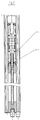
- the one-piece profile screwed to a fixed holder 7 has a cylinder body 2 of a rodless pressure medium cylinder and raceways 6 for rollers 5.
- the one with a sealed longitudinal slot 2a provided cylinder 2 contains a longitudinally displaceable piston 3, to which a power transmission element 4 is connected, which is formed similar to a carriage and in the present embodiment from a plurality of components screwed together.
- This element 4 is connected via support arms 4a to a load 1 to be moved, for example a relatively heavy sliding glass door.
- the rollers 5, arranged in profile below the cylinder body 2 and supported at the ends of the force transmission element 4, are functionally divided into support rollers 5a and support rollers 5b and are each provided in pairs.
- the support rollers 5b are adjustably connected to the force transmission element 4 in the direction of their track 6.
- the raceways 6 and the support rollers 5a formed at least in the area of their running surface from non-metallic material and the support rollers 5b are coordinated with one another in their cross section such that the rollers 5a and 5b are in linear contact with the raceways 6 on both sides. This can be easily achieved, for example, by designing the rollers 5a and 5b in the area of their running surface as semicircular as shown and the raceways 6 in cross section similar to a Gothic arch (not shown).
- the axis of rotation of the support rollers 5a and the support rollers 5b and the direction of action of the load 1 to be moved are at an angle of 90 ° to one another.
- the power transmission takes place on the one hand between the support rollers 5a or the support rollers 5b and the raceways 6 and on the other hand between the profile and the fixed holder 7 in common working planes, so that none of the width of the longitudinal slot 2a changing moments occur.
- the profile has grooves 11a in which strip-shaped permanent magnets or steel strips 11 can be embedded.
- a pulley 9 for a rope 10 is mounted on the two longitudinal ends of the profile, the z. B. consists of steel with a casing made of plastic.
- This cable 10 is fastened to the force transmission element 4 by a clamp connection (see FIG. 6).
- a second force transmission element 4 'for a further load 1' which is to be moved in opposite directions is connected to the side of the drive cable 10 which is opposite in the longitudinal direction and rearward in relation to FIG. 1B.
- the second power transmission element 4 ' also has the support rollers 5a and the support rollers 5b. However, it is not connected to the piston 3 of the pressure cylinder.
- the piston 3 of the pressure medium cylinder is pressurized with air on one side or the other.
- the rolling path of the force transmission element 4 is limited by adjustable stops 8 arranged inside the profile, which interact with noise-damping elastic blocks 8a, which are attached to the ends of the force transmission element 4.
- the second power transmission element 4 'and thus the further load 1' are simultaneously moved via the cable 10 described.
- one of the two deflecting rollers 9 is designed as a signal disk, for example by a special profiling of its end face.
- one of the two deflection rollers 9 can be coupled to a separate signal disk. Said deflection roller 9 or the separate signal disk works with simple electrical signal transmitters together, whose pulses corresponding to the speed of rotation and the direction of rotation can be evaluated for the desired control and control functions.
- a locking mechanism is mounted within the one-piece profile and interacts positively with the force transmission element 4.
- This mechanism the z. B. can be operated by hand with the aid of a square wrench or a magnet, allows the load to be moved 1 and possibly also the other load 1 'connected via the cable 10 to be fixed.
Landscapes
- Engineering & Computer Science (AREA)
- Physics & Mathematics (AREA)
- Fluid Mechanics (AREA)
- Mechanical Engineering (AREA)
- General Engineering & Computer Science (AREA)
- Transmission Devices (AREA)
- Vehicle Body Suspensions (AREA)
- Manipulator (AREA)
- Platform Screen Doors And Railroad Systems (AREA)
- Actuator (AREA)
- Bearings For Parts Moving Linearly (AREA)
Applications Claiming Priority (2)
| Application Number | Priority Date | Filing Date | Title |
|---|---|---|---|
| DE4332547A DE4332547A1 (de) | 1993-09-24 | 1993-09-24 | Antriebs- und Führungssystem für eine zu bewegende Last |
| DE4332547 | 1993-09-24 |
Publications (2)
| Publication Number | Publication Date |
|---|---|
| EP0645544A1 true EP0645544A1 (fr) | 1995-03-29 |
| EP0645544B1 EP0645544B1 (fr) | 1998-12-30 |
Family
ID=6498528
Family Applications (1)
| Application Number | Title | Priority Date | Filing Date |
|---|---|---|---|
| EP94114794A Expired - Lifetime EP0645544B1 (fr) | 1993-09-24 | 1994-09-20 | Système de motorisation et de guidage pour mouvoir une charge |
Country Status (4)
| Country | Link |
|---|---|
| EP (1) | EP0645544B1 (fr) |
| AT (1) | ATE175257T1 (fr) |
| DE (2) | DE4332547A1 (fr) |
| DK (1) | DK0645544T3 (fr) |
Cited By (3)
| Publication number | Priority date | Publication date | Assignee | Title |
|---|---|---|---|---|
| DE19604997C2 (de) * | 1996-02-12 | 1999-07-15 | Duewag Ag | Antriebssystem für eine zu bewegende Last |
| EP1022472A2 (fr) | 1999-01-22 | 2000-07-26 | Hygrama Ag | Système d'actionnement et de guidage combiné pour une charge mobile |
| US6401593B1 (en) | 1998-09-17 | 2002-06-11 | Festo Ag & Co. | Drive and guide means for a load to be moved |
Families Citing this family (1)
| Publication number | Priority date | Publication date | Assignee | Title |
|---|---|---|---|---|
| DE19611322C2 (de) * | 1996-03-22 | 2000-05-25 | Dowaldwerke Adolf Dowald Gmbh | Antriebs- und Führungssystem |
Citations (2)
| Publication number | Priority date | Publication date | Assignee | Title |
|---|---|---|---|---|
| DE4027636A1 (de) * | 1990-08-31 | 1992-04-09 | Airtec Pneumatic Gmbh | Fluidgetriebener kolbenstangenloser arbeitszylinder |
| EP0542211A1 (fr) * | 1991-11-11 | 1993-05-19 | Smc Kabushiki Kaisha | Vérin sans tige |
Family Cites Families (2)
| Publication number | Priority date | Publication date | Assignee | Title |
|---|---|---|---|---|
| DE2404244A1 (de) * | 1974-01-30 | 1975-08-07 | Ahrendt & Birkendahl Ohg | Kolbenstangenloser arbeitszylinder |
| DE3436977A1 (de) * | 1984-10-09 | 1986-04-10 | Antriebs Steuerungstech Ges | Linearantrieb |
-
1993
- 1993-09-24 DE DE4332547A patent/DE4332547A1/de not_active Withdrawn
-
1994
- 1994-09-20 EP EP94114794A patent/EP0645544B1/fr not_active Expired - Lifetime
- 1994-09-20 DE DE59407554T patent/DE59407554D1/de not_active Expired - Fee Related
- 1994-09-20 DK DK94114794T patent/DK0645544T3/da active
- 1994-09-20 AT AT94114794T patent/ATE175257T1/de not_active IP Right Cessation
Patent Citations (2)
| Publication number | Priority date | Publication date | Assignee | Title |
|---|---|---|---|---|
| DE4027636A1 (de) * | 1990-08-31 | 1992-04-09 | Airtec Pneumatic Gmbh | Fluidgetriebener kolbenstangenloser arbeitszylinder |
| EP0542211A1 (fr) * | 1991-11-11 | 1993-05-19 | Smc Kabushiki Kaisha | Vérin sans tige |
Cited By (5)
| Publication number | Priority date | Publication date | Assignee | Title |
|---|---|---|---|---|
| DE19604997C2 (de) * | 1996-02-12 | 1999-07-15 | Duewag Ag | Antriebssystem für eine zu bewegende Last |
| US6401593B1 (en) | 1998-09-17 | 2002-06-11 | Festo Ag & Co. | Drive and guide means for a load to be moved |
| EP1022472A2 (fr) | 1999-01-22 | 2000-07-26 | Hygrama Ag | Système d'actionnement et de guidage combiné pour une charge mobile |
| AT407430B (de) * | 1999-01-22 | 2001-03-26 | Hygrama Ag | Kombiniertes antriebs- und führungssystem für eine zu bewegende last |
| EP1022472A3 (fr) * | 1999-01-22 | 2001-08-08 | Hygrama Ag | Système d'actionnement et de guidage combiné pour une charge mobile |
Also Published As
| Publication number | Publication date |
|---|---|
| EP0645544B1 (fr) | 1998-12-30 |
| ATE175257T1 (de) | 1999-01-15 |
| DE4332547A1 (de) | 1995-03-30 |
| DE59407554D1 (de) | 1999-02-11 |
| DK0645544T3 (da) | 1999-10-25 |
Similar Documents
| Publication | Publication Date | Title |
|---|---|---|
| DE3436977C2 (fr) | ||
| EP0367196B1 (fr) | Unité de guidage et d'entraînement linéaire | |
| EP0397715B1 (fr) | Installation pour travailler ou monter des pieces | |
| EP1927770A2 (fr) | Unité linéaire | |
| DE3818757A1 (de) | Portal eines industrieroboters | |
| DE29517615U1 (de) | Fluidbetätigter Arbeitszylinder | |
| DE2634104A1 (de) | Leitungswagen zum fuehren von kabeln u.dgl. | |
| EP0135041B1 (fr) | Cylindre actionneur sans tige | |
| EP0645544B1 (fr) | Système de motorisation et de guidage pour mouvoir une charge | |
| EP0802130B1 (fr) | Système de transport | |
| WO2007128771A1 (fr) | Dispositif de déplacement d'une porte coulissante déplaçable horizontalement | |
| DE2916280B2 (de) | Kombinierte Wälz-/Gleitführung als Geradführung | |
| DE9314481U1 (de) | Antriebs- und Führungssystem für eine zu bewegende Last | |
| EP0914562B1 (fr) | Entrainement lineaire sans tige de piston | |
| EP1060097B1 (fr) | Frein de voie, notamment frein de maintien | |
| EP0195740B1 (fr) | Profil d'une poutre en caisson | |
| DE3806613A1 (de) | Antriebsvorrichtung zum spielfreien umwandeln einer drehbewegung in eine linearbewegung | |
| EP1108906A1 (fr) | Dispositif de guide lineaire | |
| EP1612436B1 (fr) | Guide linéaire avec rail profilé | |
| EP0649503B1 (fr) | Palier d'appui pour unites en mouvement a guidage lineaire | |
| DE10125381B4 (de) | Lagerblock mit Stange | |
| DE4022574C2 (fr) | ||
| DE3907440A1 (de) | Hubschlitten | |
| EP0103852A1 (fr) | Commande linéaire | |
| DE4142061A1 (de) | Geradefuehrungseinheit mit synchron verschobenem waelzlagerelement-kaefig |
Legal Events
| Date | Code | Title | Description |
|---|---|---|---|
| PUAI | Public reference made under article 153(3) epc to a published international application that has entered the european phase |
Free format text: ORIGINAL CODE: 0009012 |
|
| AK | Designated contracting states |
Kind code of ref document: A1 Designated state(s): AT DE DK ES FR GB IT NL SE |
|
| 17P | Request for examination filed |
Effective date: 19950922 |
|
| 17Q | First examination report despatched |
Effective date: 19961213 |
|
| RAP1 | Party data changed (applicant data changed or rights of an application transferred) |
Owner name: IMI NORGREN GMBH Owner name: DUEWAG AKTIENGESELLSCHAFT |
|
| GRAG | Despatch of communication of intention to grant |
Free format text: ORIGINAL CODE: EPIDOS AGRA |
|
| GRAG | Despatch of communication of intention to grant |
Free format text: ORIGINAL CODE: EPIDOS AGRA |
|
| GRAH | Despatch of communication of intention to grant a patent |
Free format text: ORIGINAL CODE: EPIDOS IGRA |
|
| GRAH | Despatch of communication of intention to grant a patent |
Free format text: ORIGINAL CODE: EPIDOS IGRA |
|
| GRAA | (expected) grant |
Free format text: ORIGINAL CODE: 0009210 |
|
| AK | Designated contracting states |
Kind code of ref document: B1 Designated state(s): AT DE DK ES FR GB IT NL SE |
|
| PG25 | Lapsed in a contracting state [announced via postgrant information from national office to epo] |
Ref country code: NL Free format text: LAPSE BECAUSE OF FAILURE TO SUBMIT A TRANSLATION OF THE DESCRIPTION OR TO PAY THE FEE WITHIN THE PRESCRIBED TIME-LIMIT Effective date: 19981230 Ref country code: IT Free format text: LAPSE BECAUSE OF FAILURE TO SUBMIT A TRANSLATION OF THE DESCRIPTION OR TO PAY THE FEE WITHIN THE PRESCRIBED TIME-LIMIT;WARNING: LAPSES OF ITALIAN PATENTS WITH EFFECTIVE DATE BEFORE 2007 MAY HAVE OCCURRED AT ANY TIME BEFORE 2007. THE CORRECT EFFECTIVE DATE MAY BE DIFFERENT FROM THE ONE RECORDED. Effective date: 19981230 Ref country code: ES Free format text: THE PATENT HAS BEEN ANNULLED BY A DECISION OF A NATIONAL AUTHORITY Effective date: 19981230 |
|
| REF | Corresponds to: |
Ref document number: 175257 Country of ref document: AT Date of ref document: 19990115 Kind code of ref document: T |
|
| REF | Corresponds to: |
Ref document number: 59407554 Country of ref document: DE Date of ref document: 19990211 |
|
| GBT | Gb: translation of ep patent filed (gb section 77(6)(a)/1977) |
Effective date: 19990331 |
|
| ET | Fr: translation filed | ||
| NLV1 | Nl: lapsed or annulled due to failure to fulfill the requirements of art. 29p and 29m of the patents act | ||
| RAP2 | Party data changed (patent owner data changed or rights of a patent transferred) |
Owner name: IMI NORGREN GMBH Owner name: SIEMENS DUEWAG SCHIENENFAHRZEUGE GMBH |
|
| REG | Reference to a national code |
Ref country code: DK Ref legal event code: T3 |
|
| PLBE | No opposition filed within time limit |
Free format text: ORIGINAL CODE: 0009261 |
|
| STAA | Information on the status of an ep patent application or granted ep patent |
Free format text: STATUS: NO OPPOSITION FILED WITHIN TIME LIMIT |
|
| 26N | No opposition filed | ||
| REG | Reference to a national code |
Ref country code: GB Ref legal event code: 732E |
|
| REG | Reference to a national code |
Ref country code: FR Ref legal event code: TQ |
|
| REG | Reference to a national code |
Ref country code: GB Ref legal event code: IF02 |
|
| REG | Reference to a national code |
Ref country code: GB Ref legal event code: 732E |
|
| REG | Reference to a national code |
Ref country code: FR Ref legal event code: TP |
|
| PGFP | Annual fee paid to national office [announced via postgrant information from national office to epo] |
Ref country code: DK Payment date: 20050905 Year of fee payment: 12 |
|
| PGFP | Annual fee paid to national office [announced via postgrant information from national office to epo] |
Ref country code: SE Payment date: 20050906 Year of fee payment: 12 |
|
| PGFP | Annual fee paid to national office [announced via postgrant information from national office to epo] |
Ref country code: AT Payment date: 20050907 Year of fee payment: 12 |
|
| PG25 | Lapsed in a contracting state [announced via postgrant information from national office to epo] |
Ref country code: AT Free format text: LAPSE BECAUSE OF NON-PAYMENT OF DUE FEES Effective date: 20060920 |
|
| PG25 | Lapsed in a contracting state [announced via postgrant information from national office to epo] |
Ref country code: SE Free format text: LAPSE BECAUSE OF NON-PAYMENT OF DUE FEES Effective date: 20060921 |
|
| PG25 | Lapsed in a contracting state [announced via postgrant information from national office to epo] |
Ref country code: DK Free format text: LAPSE BECAUSE OF NON-PAYMENT OF DUE FEES Effective date: 20061002 |
|
| REG | Reference to a national code |
Ref country code: DK Ref legal event code: EBP |
|
| EUG | Se: european patent has lapsed | ||
| PGFP | Annual fee paid to national office [announced via postgrant information from national office to epo] |
Ref country code: GB Payment date: 20070910 Year of fee payment: 14 |
|
| PGFP | Annual fee paid to national office [announced via postgrant information from national office to epo] |
Ref country code: DE Payment date: 20071122 Year of fee payment: 14 |
|
| PGFP | Annual fee paid to national office [announced via postgrant information from national office to epo] |
Ref country code: FR Payment date: 20070918 Year of fee payment: 14 |
|
| GBPC | Gb: european patent ceased through non-payment of renewal fee |
Effective date: 20080920 |
|
| REG | Reference to a national code |
Ref country code: FR Ref legal event code: ST Effective date: 20090529 |
|
| PG25 | Lapsed in a contracting state [announced via postgrant information from national office to epo] |
Ref country code: DE Free format text: LAPSE BECAUSE OF NON-PAYMENT OF DUE FEES Effective date: 20090401 |
|
| PG25 | Lapsed in a contracting state [announced via postgrant information from national office to epo] |
Ref country code: FR Free format text: LAPSE BECAUSE OF NON-PAYMENT OF DUE FEES Effective date: 20080930 |
|
| PG25 | Lapsed in a contracting state [announced via postgrant information from national office to epo] |
Ref country code: GB Free format text: LAPSE BECAUSE OF NON-PAYMENT OF DUE FEES Effective date: 20080920 |