EP0645133B1 - Hydromassagegewanne mit Rotationsverteiler - Google Patents
Hydromassagegewanne mit Rotationsverteiler Download PDFInfo
- Publication number
- EP0645133B1 EP0645133B1 EP94202732A EP94202732A EP0645133B1 EP 0645133 B1 EP0645133 B1 EP 0645133B1 EP 94202732 A EP94202732 A EP 94202732A EP 94202732 A EP94202732 A EP 94202732A EP 0645133 B1 EP0645133 B1 EP 0645133B1
- Authority
- EP
- European Patent Office
- Prior art keywords
- nozzles
- bath tub
- hydromassage
- holes
- duct
- Prior art date
- Legal status (The legal status is an assumption and is not a legal conclusion. Google has not performed a legal analysis and makes no representation as to the accuracy of the status listed.)
- Expired - Lifetime
Links
- 239000007788 liquid Substances 0.000 claims description 25
- 230000009471 action Effects 0.000 claims description 5
- 238000004891 communication Methods 0.000 claims description 3
- 238000007789 sealing Methods 0.000 claims description 3
- 239000002699 waste material Substances 0.000 claims description 3
- 230000001154 acute effect Effects 0.000 claims description 2
- XLYOFNOQVPJJNP-UHFFFAOYSA-N water Substances O XLYOFNOQVPJJNP-UHFFFAOYSA-N 0.000 description 15
- 238000007599 discharging Methods 0.000 description 7
- 239000002131 composite material Substances 0.000 description 6
- 239000012530 fluid Substances 0.000 description 3
- 230000009467 reduction Effects 0.000 description 3
- 230000000694 effects Effects 0.000 description 2
- 238000012423 maintenance Methods 0.000 description 2
- 238000000465 moulding Methods 0.000 description 2
- 230000003213 activating effect Effects 0.000 description 1
- 230000004913 activation Effects 0.000 description 1
- 230000000712 assembly Effects 0.000 description 1
- 238000000429 assembly Methods 0.000 description 1
- 230000002860 competitive effect Effects 0.000 description 1
- 230000005484 gravity Effects 0.000 description 1
- 238000009434 installation Methods 0.000 description 1
- 238000012986 modification Methods 0.000 description 1
- 230000004048 modification Effects 0.000 description 1
- 238000000554 physical therapy Methods 0.000 description 1
Images

Classifications
-
- A—HUMAN NECESSITIES
- A61—MEDICAL OR VETERINARY SCIENCE; HYGIENE
- A61H—PHYSICAL THERAPY APPARATUS, e.g. DEVICES FOR LOCATING OR STIMULATING REFLEX POINTS IN THE BODY; ARTIFICIAL RESPIRATION; MASSAGE; BATHING DEVICES FOR SPECIAL THERAPEUTIC OR HYGIENIC PURPOSES OR SPECIFIC PARTS OF THE BODY
- A61H33/00—Bathing devices for special therapeutic or hygienic purposes
- A61H33/0087—Therapeutic baths with agitated or circulated water
-
- A—HUMAN NECESSITIES
- A61—MEDICAL OR VETERINARY SCIENCE; HYGIENE
- A61H—PHYSICAL THERAPY APPARATUS, e.g. DEVICES FOR LOCATING OR STIMULATING REFLEX POINTS IN THE BODY; ARTIFICIAL RESPIRATION; MASSAGE; BATHING DEVICES FOR SPECIAL THERAPEUTIC OR HYGIENIC PURPOSES OR SPECIFIC PARTS OF THE BODY
- A61H33/00—Bathing devices for special therapeutic or hygienic purposes
- A61H33/60—Components specifically designed for the therapeutic baths of groups A61H33/00
- A61H33/601—Inlet to the bath
- A61H33/6021—Nozzles
-
- A—HUMAN NECESSITIES
- A61—MEDICAL OR VETERINARY SCIENCE; HYGIENE
- A61H—PHYSICAL THERAPY APPARATUS, e.g. DEVICES FOR LOCATING OR STIMULATING REFLEX POINTS IN THE BODY; ARTIFICIAL RESPIRATION; MASSAGE; BATHING DEVICES FOR SPECIAL THERAPEUTIC OR HYGIENIC PURPOSES OR SPECIFIC PARTS OF THE BODY
- A61H2201/00—Characteristics of apparatus not provided for in the preceding codes
- A61H2201/16—Physical interface with patient
- A61H2201/1602—Physical interface with patient kind of interface, e.g. head rest, knee support or lumbar support
- A61H2201/1623—Back
-
- A—HUMAN NECESSITIES
- A61—MEDICAL OR VETERINARY SCIENCE; HYGIENE
- A61H—PHYSICAL THERAPY APPARATUS, e.g. DEVICES FOR LOCATING OR STIMULATING REFLEX POINTS IN THE BODY; ARTIFICIAL RESPIRATION; MASSAGE; BATHING DEVICES FOR SPECIAL THERAPEUTIC OR HYGIENIC PURPOSES OR SPECIFIC PARTS OF THE BODY
- A61H2201/00—Characteristics of apparatus not provided for in the preceding codes
- A61H2201/50—Control means thereof
- A61H2201/5053—Control means thereof mechanically controlled
Definitions
- the present invention relates to bathtubs for hydromassage in general and more particularly to bathtubs provided with means for hydromassaging the back.
- Hydromassage of the abovementioned type differs from that carried out. on other parts of the body on account of the special way in which it is achieved.
- all the supply vents or nozzles function simultaneously
- they are supplied in succession in one direction (from the bottom upwards) or in the opposite direction. After the desired sequence has been chosen, it is repeated cyclically for a predetermined period of time, depending on the effects which are to be obtained.
- the nozzle activation cycle as described here, can be explained in that the action of this type of hydromassage reproduces the action of a traditional manual massage performed by Shiatzu masseurs or physiotherapists. It is sufficient to mention just one of the advantages offered by this type of hydromassage, i.e. the significant reduction in cost, to understand the huge success of bathtubs which can be used for this purpose and the consequent research efforts by manufacturers to achieve reliable and competitive technical solutions.
- Bathtubs which allow the user to undergo hydromassaging of the back are in fact known and it is also known that generally they are provided with suitable programming means for activating and supplying the vents or nozzles delivering the liquid under pressure, as described above.
- These programming means which are for example of the electronic type in the more sophisticated models of bath, control sequential opening and closing of solenoid valves inserted in the supply ducts of the various nozzles.
- EP-A-0 154 935 discloses a kind of hydromassage device for physiotherapy comprising a tank or tub and provided with two kinds of jet assemblies : a first one mounted on a means for intermittently dispensing pressurized fluid consisting of a reciprocating element accomodating a first plurality of nozzles delivering fluid under pressure and a scond one, consisting of a plurality of axially aligned nozzles, located in the backrest of the tub and activated in succession from the bottom towards the top and vice versa.
- a bath tub according to the appended claim 1 is more specifically the subject of the present invention.
- a bathtub for underwater massage with water jets having a water supplying apparatus composed of stationary and movable members is known from DE-B-1087761.
- Said apparatus is a rotatable water deliverying assembly since its movable member is rotatable within the stationary member. More particularly both said rotatable and stationary members consist of a tubular pipe.
- the water under pressure is introduced into the rotatable pipe which is provided with series of holes which are angularly offset in the longitudinal direction and are designed to be positioned, as a result of rotation of said pipe, opposite a corresponding series of holes of the stationary pipe, these holes having a rectilinear pattern.
- its distributor of water therein is a rotating distributor by which the sequential feeding of the nozzles is achieved.
- EP-A-286304 is known a bath installation using a rotary sequency distributor for supplying in turn with a fluid successive groups of openings distributed in different zones of the bottom and walls of the bathtub.
- means are provided at the outlet of said distributor for the automatic discharging of the residual liquid from the latter when hydromassage has been terminated.
- Said discharging means are activated, i.e. opened, when a sensor of the liquid level detects a minimum level of liquid in the bathtub sending a suitable signal to a valve means inserted in a duct connecting the outlet of the distributor with the bathtub waste outlet.
- FR-A-2398851 a distribution apparatus of water is described the configuration of their feeding ducts being that these latter allow to obtain the discharging of the water from the apparatus when its use is terminated.
- the discharging of the water is simply obtained by gravity since all the various water feeding ducts are inclined towards the bottom in the direction of a discharging device which is the lowest part of the apparatus.
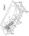
- the backrest denoted overall by 10, has two series of vents or nozzles 12 for delivering a liquid under pressure, such as water for example.
- the nozzles 12 of each of the two series are aligned in a direction substantially parallel to the longitudinal median axis of the backrest 10 and the two series of nozzles 12 are parallel to each other and are composed of an equal number of nozzles 12 which are equidistant with. respect to each other.
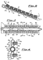
- nozzles 12 of each series are mounted in pairs, as described in more detail below, on the upper side, i.e. on the side where the backrest 10 of the bath is located, of chambers 14 formed longitudinally in two parallel and symmetrical rows with respect to a composite central longitudinal duct 16 on two tubular portions denoted overall by 18a and 18b, respectively.
- the external wall 16a of the duct 16 and the portions 18a, 18b are formed as one piece.
- this assembly may be made of plastic and hence be obtained simply by means of moulding with a significant reduction in costs.
- the chambers 14 which are located opposite one another symmetrically with respect to the composite central duct 16 may, however, assume two different and separate operating conditions.. They may, in fact, be respectively separated from one another or in communication with one another depending on the configuration assumed by the composite central duct 16 which, as will be explained below, performs the important function of a rotating distributor.
- the chambers 14 in question are supplied simultaneously with liquid under pressure by the composite central duct or rotating distributor 16, supplying in turn the two pairs of nozzles 12 associated with them.
- the composite central duct or rotating distributor 16 comprises, within said external wall 16a, an essentially cylindrical sleeve 20, the ends of which are arranged in a fixed position in suitable seats provided at the ends of the tubular portions 18a, 18b.
- the sleeve 20 is open at the ends, into one of which the liquid under pressure coming from a known supply pump 27 connected inside the bath via a duct 29 is introduced.
- the sleeve 20, at the other end, is connected to a duct 21 connected in turn to the waste outlet of the tub.
- the duct 21 has inside it a solenoid valve 23 which is connected to a suitable electronic sensor 25 for detecting the level of the liquid inside the bathtub, indicated by a broken line in the illustration, said sensor being fixed in any known manner on one of the external walls of the tub, for example the rear wall as shown in Figure 1.
- This sensor 25, known per se is calibrated so as to emit a control signal for opening the solenoid valve 23 when the level of water inside the tub, during its emptying at the end of the hydromassage, has reached a predetermined minimum value.
- This value for example, corresponds substantially to the height at which the lower delivery nozzles 12 are located with respect to the bottom of the bathtub.
- the sleeve 20 is provided with openings 22 ( Figure 4) which allow the liquid under pressure to flow inside said chambers.
- openings 22 Figure 4
- the liquid under pressure is introduced in succession into each pair of chambers 14 located opposite one another, i.e. in communication with each other as described above, in one direction or in the opposite direction.
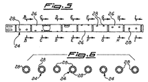
- the holes 28 are grouped together, in the example of embodiment considered, in fours on portions 26 of equal length of the duct 24.
- the four holes 28 of each portion 26 are arranged in pairs in a diametral plane, i.e. are arranged at 180°, while the holes of each portion 26 with respect to the preceding portion are offset at a predefined and constant angle, generally an acute angle. In this way the holes 28 are distributed over the duct 24 substantially in two helices.
- the conditions in which the hydromassage is performed may be varied according to the user's needs and requirements. For example, increasing or reducing the speed of rotation of the duct 24 causes, respectively, a reduction or increase in the duration of the supply sequence of the nozzles 12.
- the force of the jets emerging from the nozzles 12 may be varied for example by modifying the delivery of the liquid supply pump and this in particular enables one to increase or decrease the pressure with which the jets of said liquid reach the user's body.
- the assembly consisting of the composite central longitudinal duct 16 and the two tubular portions 18a and 18b is fixed to the rear wall of the backrest 10.
- a description is now given, by way of a non-limiting example, of a possible embodiment of this fixing system.
- the abovementioned assembly is first of all simply rested on the rear surface of the said backrest 10 of the tub, inside a suitable seat in the latter.
- the nozzles 12 are applied and fixed, through holes in said backrest 10, to the tubular portions 18a, 18b, thus fixing in this way the entire assembly to the bathtub.
- the walls of the tubular portions 18a, 18b to which the nozzles 12 are applied are provided with sleeve elements 30 of essentially cylindrical shape, the middle zone of which is sealingly fixed in any known manner to said walls.
- the portions 30a of the sleeve elements 30 which project outside the chambers 14 are threaded internally so that a corresponding threaded portion of the body of the nozzles 12 allows the latter to be screwed inside them.
- the top end of the body of the nozzles 12, i.e. the end arranged inside the tub, has an annular projection 12a which engages with the inner side of the backrest 10, thereby providing the abovementioned fixing system since the end of the portions 30a of the sleeves 30 engages with the external surface of the backrest 10.
- annular grooves On the end of the body of the nozzles 12 opposite to the preceding end there are formed annular grooves, two in the example considered, inside each of which a seal 32 is mounted, said seal being provided so as to ensure a sealing action when the abovementioned end of the nozzles 12 is inserted into the portion 30b of the sleeve elements 30 which is located inside the chambers 14.
- the reason why two, or in somes cases more than two, seals 32 are provided is in order to ensure the sealing action in all circumstances, namely engagement of at least one seal 32 in said portion 30b of the sleeves 30, independently of the wall thickness of the backrest 10, which may vary from one bathtub to another.
- holes 28 on the duct 24 must be regarded solely as an example of embodiment since the same effects could be obtained by providing said duct with longitudinal eyelets, each of which would replace a pair of holes 28, while, as regards the rest, these eyelets would be arranged, from one portion 26 to the next, offset in the same manner as the holes in question.
- the tub By providing the rotating distributor for carrying out the hydromassage of the back, the tub is simplified and the cost thereof reduced.
- the abovementioned distributor has made it possible to eliminate, or at least has entirely replaced, all the complex programming means provided in conventional bathtubs.
Landscapes
- Health & Medical Sciences (AREA)
- Public Health (AREA)
- Life Sciences & Earth Sciences (AREA)
- Pain & Pain Management (AREA)
- Physical Education & Sports Medicine (AREA)
- Rehabilitation Therapy (AREA)
- Epidemiology (AREA)
- Animal Behavior & Ethology (AREA)
- General Health & Medical Sciences (AREA)
- Veterinary Medicine (AREA)
- Percussion Or Vibration Massage (AREA)
- Devices For Medical Bathing And Washing (AREA)
- Nozzles (AREA)
Claims (13)
- Badewanne für Hydromassage mit einer Vorrichtung für die Hydromassage des Rückens des Benutzers, mit mindestens einer Reihe von Düsen (12) zum Liefern einer Flüssigkeit unter Druck, wobei jede Reihe von Düsen (12) mindestens ungefähr parallel zu der Mittelachse der Rückenlehnenwand der Wanne ist, und einem Verteiler, der angepaßt ist an das Zuführendadurch gekennzeichnet,gemäß einer vorbestimmten Abfolge, die zyklisch während einer vorbestimmten Zeitdauer wiederholt wird - der von einer Lieferquelle (27) gelieferten Flüssigkeit zu den Düsen (12), wobei der Verteiler aufweist:ein erstes stationäres Teil (20), das mit der Quelle (27) verbunden ist und mit Öffnungen (22) versehen ist, die geeignet sind zum Ermöglichen, daß die Flüssigkeit unter Druck von der Quelle (27) zu den Düsen (12) fließt, undein zweites Teil (24), das innerhalb des ersten Teiles (20) angeordnet ist, und drehend bewegbar in bezug auf dasselbe ist, wobei das zweite Teil mit einer Mehrzahl von Löchern (28) versehen ist, wodurch die Drehbewegung des zweiten Teiles (24) in bezug auf das erste Teil (20) bewirkt, daß die in dem zweiten Teil vorgesehenen Löcher (28) in und aus der Ausrichtung mit den in dem ersten Teil (20) vorgesehenen Öffnungen (22) kommen,daß der Verteiler auch eine Leitung oder Gehäuse (16), die/das das erste Teil (20) umgibt, und eine Mehrzahl von Kammern (14), auf denen die Düsen (12) in Verbindung damit angebracht sind, aufweist,und daß die Anordnung der in dem zweiten Teil (24) vorgesehenen Löcher (28) derart ist, daß die Drehung des letzteren in bezug auf das erste Teil (20) bewirkt, daß die Flüssigkeit unter Druck aufeinanderfolgend in die verschiedenen Kammern (14) eingeführt wird, wenn die gleichen Löcher (28) mit den in dem ersten Teil (20) vorgesehenen entsprechenden Öffnungen (22) ausgerichtet sind, so daß eine Abfolge von Flüssigkeitsstrahlen erzielt wird, die aus den Düsen (12) austreten.
- Badewanne für Hydromassage nach Anspruch 1, dadurch gekennzeichnet, daß die Kammern (14) längsweise in zwei parallelen Reihen getrennt voneinander auf diametral gegenüberliegenden Röhrenabschnitten (18a, 18b) gebildet sind, die bevorzugt als eine Einstückanordnung mit der externen Wand (16a) der Leitung oder des Gehäuses (16) gebildet sind.
- Badewanne für Hydromassage nach Anspruch 1 oder 2, dadurch gekennzeichnet, daß das zweite Teil (24) durch einen Röhrenkörper gebildet ist, auf dem die Löcher (28), die darin vorgesehen sind, im bezug aufeinander versetzt sind.
- Badewanne für Hydromassage nach Anspruch 3, dadurch gekennzeichnet, daß das zweite Teil (24) aus einer Mehrzahl von Abschnitten (26) besteht, bevorzugt einer gleichen Länge, auf denen die Löcher (28) diametral gegenüberliegend in mindestens einem Paar angeordnet sind, wobei die Löcher (28) eines jeden der Abschnitte (26) in einem bevorzugten und konstanten Winkel, allgemein ein spitzer Winkel, versetzt sind.
- Badewanne für Hydromassage nach einem der vorhergehenden Ansprüche, dadurch gekennzeichnet, daß jede Reihe von Düsen (12) aus einer gleichen Zahl von Düsen zusammengesetzt ist, die in gleichen Abständen in bezug aufeinander vorgesehen sind.
- Badewanne für Hydromassage nach einem der vorhergehenden Ansprüche, dadurch gekennzeichnet, daß jede Düse (12) an der zugehörigen Kammer (14) mittels eines Hülsenelementes (30) befestigt ist, das auf derselben vorgesehen ist und in Verbindung damit steht.
- Badewanne für Hydromassage nach Anspruch 6, dadurch gekennzeichnet, daß das Hülsenelement (30), das von im wesentlichen zylindrischer Form ist, aus einem ersten Abschnitt (30a), der außerhalb der Kammer (14) für eine Gewindeverbindung mit einem entsprechenden Abschnitt der Düse (12) vorsteht, und einen zweiten Abschnitt (30b) innerhalb der Kammer (14) für eine abgedichtete Verbindung mit einem anderen entsprechenden Abschnitt der gleichen Düse (12) besteht.
- Badewanne für Hydromassage nach einem der Ansprüche 2 bis 7, dadurch gekennzeichnet, daß die Anordnung, die aus der Leitung oder dem Gehäuse (16) und den Röhrenabschnitten (18a, 18b) besteht, extern an der Rückwand der Rückenlehnenwand (10) so angebracht und befestigt ist, daß sie an den Enden der Düsen (12) befestigt ist, die von der Außenoberfläche der Wanne vorstehen.
- Badewanne für Hydromassage nach Anspruch 7 oder 8, dadurch gekennzeichnet, daß die abgedichtete Verbindung des zweiten Abschnittes (30b) der Hülse (30) innerhalb der Kammer (14) mit einem entsprechenden Abschnitt der Düse (12) mindestens ein Paar von Dichtungen (32) benutzt, die längsweise voneinander beabstandet sind, zum Sicherstellen einer geeigneten Abdichtwirkung unabhängig von der Dicke der Rückenlehne (10).
- Badewanne für Hydromassage nach einem der vorhergehenden Ansprüche, dadurch gekennzeichnet, daß die Dauer der Abfolge, mit der die Düsen (12) mit der Flüssigkeit durch den Verteiler beliefert werden, durch die Drehgeschwindigkeit des zweiten Teiles (24) in bezug auf das erste stationäre Teil (20) bestimmt ist.
- Badewanne für Hydromassage nach einem der vorhergehenden Ansprüche, dadurch gekennzeichnet, daß der Verteiler ebenfalls mit einer Leitung (21) verbunden ist, die wiederum mit dem Abwasserauslaß der Badewanne verbunden ist, so daß die Restflüssigkeit an dem Ende der Benutzung vollständig ausgegeben wird.
- Badewanne für Hydromassage nach Anspruch 11, das Ventilmittel (23) in der Leitung (21) vorgesehen sind, die durch ein Erfassungsmittel (25) zum Erfassen, wann der Pegel der Flüssigkeit in der Badewanne einen vorbestimmten Minimalwert während des Entleerens an dem Ende der Benutzung erreicht hat, aktiviert werden.
- Badewanne für Hydromassage nach Anspruch 12, dadurch gekennzeichnet, daß der vorbestimmte Minimalwert des Pegels der Flüssigkeit im wesentlichen der Höhe der untersten der Düsen (12) in bezug auf den Boden der Wanne entspricht.
Applications Claiming Priority (2)
| Application Number | Priority Date | Filing Date | Title |
|---|---|---|---|
| ITPD930192A IT1263696B (it) | 1993-09-27 | 1993-09-27 | Vasca da bagno per idromassaggio, in particolare idromassaggio dorsale |
| ITPD930192 | 1993-09-27 |
Publications (2)
| Publication Number | Publication Date |
|---|---|
| EP0645133A1 EP0645133A1 (de) | 1995-03-29 |
| EP0645133B1 true EP0645133B1 (de) | 2002-12-11 |
Family
ID=11390449
Family Applications (1)
| Application Number | Title | Priority Date | Filing Date |
|---|---|---|---|
| EP94202732A Expired - Lifetime EP0645133B1 (de) | 1993-09-27 | 1994-09-22 | Hydromassagegewanne mit Rotationsverteiler |
Country Status (7)
| Country | Link |
|---|---|
| EP (1) | EP0645133B1 (de) |
| JP (1) | JPH07148214A (de) |
| BR (1) | BR9403862A (de) |
| CA (1) | CA2132901A1 (de) |
| DE (1) | DE69431863T2 (de) |
| ES (1) | ES2185641T3 (de) |
| IT (1) | IT1263696B (de) |
Families Citing this family (7)
| Publication number | Priority date | Publication date | Assignee | Title |
|---|---|---|---|---|
| FR2734155B1 (fr) * | 1995-05-19 | 1997-11-07 | Aubert Alain | Dispositif d'hydrotherapie notamment adaptable a une cabine de douche |
| DE202005019335U1 (de) * | 2005-12-10 | 2006-01-26 | Heuberger, Tobias | Vorrichtung zur Zuführung von Fluiden zu einer Wanne |
| JP4646259B2 (ja) * | 2008-07-22 | 2011-03-09 | 株式会社日本メディックス | 液体式マッサージ装置 |
| JP4590488B2 (ja) * | 2009-03-31 | 2010-12-01 | 株式会社日本メディックス | 液体式マッサージ装置 |
| DE202010016928U1 (de) | 2010-12-23 | 2011-08-09 | Gunther Stolz | Therapiewanne mit einer geneigten Rückenanlage-Wand |
| CN106923716A (zh) * | 2017-05-16 | 2017-07-07 | 吴为生 | 多功能浴缸 |
| CN113081723B (zh) * | 2021-03-30 | 2023-04-07 | 未来穿戴技术有限公司 | 按摩控制方法及按摩仪、计算机可读存储介质 |
Family Cites Families (6)
| Publication number | Priority date | Publication date | Assignee | Title |
|---|---|---|---|---|
| DE1087761B (de) * | 1953-10-29 | 1960-08-25 | Burkhardt Hoffmann Dipl Ing | Vorrichtung zur Erzeugung wandernder Unterwasserdruckpolster in einer Wanne |
| FR2364026A2 (fr) * | 1976-09-13 | 1978-04-07 | Duclaux Jean Paul | Perfectionnement d'une installation de traitement hydrotherapique |
| FR2398851A1 (fr) * | 1977-07-26 | 1979-02-23 | Nicollet Michel | Dispositif de distribution d'eau dans un appareil de massage sous eau |
| ES285113Y (es) * | 1984-03-13 | 1986-09-01 | Conti Francesco | Dispositivo para hidromasajes |
| FR2610519B1 (fr) * | 1987-02-05 | 1990-02-23 | Gedouin Jean | Baignoire d'hydromassage |
| GB8708377D0 (en) * | 1987-04-08 | 1987-05-13 | Stewart Products Ltd Leigh | Spa baths |
-
1993
- 1993-09-27 IT ITPD930192A patent/IT1263696B/it active IP Right Grant
-
1994
- 1994-09-22 ES ES94202732T patent/ES2185641T3/es not_active Expired - Lifetime
- 1994-09-22 EP EP94202732A patent/EP0645133B1/de not_active Expired - Lifetime
- 1994-09-22 DE DE69431863T patent/DE69431863T2/de not_active Expired - Lifetime
- 1994-09-26 CA CA002132901A patent/CA2132901A1/en not_active Abandoned
- 1994-09-26 BR BR9403862A patent/BR9403862A/pt not_active Application Discontinuation
- 1994-09-27 JP JP6257562A patent/JPH07148214A/ja active Pending
Also Published As
| Publication number | Publication date |
|---|---|
| ITPD930192A0 (it) | 1993-09-27 |
| ITPD930192A1 (it) | 1995-03-27 |
| DE69431863T2 (de) | 2003-09-04 |
| JPH07148214A (ja) | 1995-06-13 |
| EP0645133A1 (de) | 1995-03-29 |
| BR9403862A (pt) | 1995-05-30 |
| ES2185641T3 (es) | 2003-05-01 |
| CA2132901A1 (en) | 1995-03-28 |
| IT1263696B (it) | 1996-08-27 |
| DE69431863D1 (de) | 2003-01-23 |
Similar Documents
| Publication | Publication Date | Title |
|---|---|---|
| KR100401360B1 (ko) | 세탁기용급수디스펜서 | |
| US4382424A (en) | Automatic apparatus for cleaning dogs and similar animals | |
| EP0252435B1 (de) | Verfahren und Gerät zur Reinigung der Rohrleitungen einer Badeanlage | |
| KR920017619A (ko) | 식기 세정기 | |
| EP0645133B1 (de) | Hydromassagegewanne mit Rotationsverteiler | |
| CA2126641A1 (en) | Hydrotherapy seat structure for a hydrotherapy spa, tub or swimming pool | |
| KR940000125B1 (ko) | 인체국부세척기의 분출장치 | |
| KR20160149675A (ko) | 식기세척기 및 그 제어방법 | |
| KR100212427B1 (ko) | 분사노즐 조립체를 구비한 세탁기 | |
| KR20060127261A (ko) | 프린팅 유닛의 잉크챔버 세척방법 및 그 시스템 | |
| US3021863A (en) | Dispensing mechanism | |
| US12343739B2 (en) | Multipurpose shower head | |
| EP0500737A4 (en) | Detergent dispenser in a dishwashing machine | |
| US7182090B2 (en) | System for cleaning components of a water retaining device, associated water retaining device, and water propulsion device for use therein | |
| US4823818A (en) | Dispensing device for washing products for a dishwashing machine | |
| KR100480726B1 (ko) | 세탁기 및 그 제어방법 | |
| EP0034123A2 (de) | Automatische Waschvorrichtung für Hunde und ähnliche Tiere | |
| JPS6467289A (en) | Method and apparatus for cleaning the inner wall surface of passageway | |
| JP4625835B2 (ja) | 頭部・顔部洗浄装置 | |
| JPS6480483A (en) | Apparatus for cleaning the interior of pipe | |
| JP4484973B2 (ja) | 頭部・顔部洗浄装置 | |
| KR970010954B1 (ko) | 두발세척기 | |
| KR0134839Y1 (ko) | 전자동 세탁기의 샤워 급수 구조 | |
| EP0864290A3 (de) | Zufuhr- und Dosiervorrichtung der Waschflüssigkeit in einer Geschirrspülmaschine | |
| KR101615258B1 (ko) | 식기세척기 |
Legal Events
| Date | Code | Title | Description |
|---|---|---|---|
| PUAI | Public reference made under article 153(3) epc to a published international application that has entered the european phase |
Free format text: ORIGINAL CODE: 0009012 |
|
| AK | Designated contracting states |
Kind code of ref document: A1 Designated state(s): DE ES FR GB IT |
|
| 17P | Request for examination filed |
Effective date: 19950915 |
|
| 17Q | First examination report despatched |
Effective date: 19970905 |
|
| GRAG | Despatch of communication of intention to grant |
Free format text: ORIGINAL CODE: EPIDOS AGRA |
|
| GRAG | Despatch of communication of intention to grant |
Free format text: ORIGINAL CODE: EPIDOS AGRA |
|
| GRAH | Despatch of communication of intention to grant a patent |
Free format text: ORIGINAL CODE: EPIDOS IGRA |
|
| GRAH | Despatch of communication of intention to grant a patent |
Free format text: ORIGINAL CODE: EPIDOS IGRA |
|
| GRAA | (expected) grant |
Free format text: ORIGINAL CODE: 0009210 |
|
| AK | Designated contracting states |
Kind code of ref document: B1 Designated state(s): DE ES FR GB IT |
|
| REG | Reference to a national code |
Ref country code: GB Ref legal event code: FG4D |
|
| REF | Corresponds to: |
Ref document number: 69431863 Country of ref document: DE Date of ref document: 20030123 |
|
| REG | Reference to a national code |
Ref country code: ES Ref legal event code: FG2A Ref document number: 2185641 Country of ref document: ES Kind code of ref document: T3 |
|
| ET | Fr: translation filed | ||
| PLBE | No opposition filed within time limit |
Free format text: ORIGINAL CODE: 0009261 |
|
| STAA | Information on the status of an ep patent application or granted ep patent |
Free format text: STATUS: NO OPPOSITION FILED WITHIN TIME LIMIT |
|
| 26N | No opposition filed |
Effective date: 20030912 |
|
| PGFP | Annual fee paid to national office [announced via postgrant information from national office to epo] |
Ref country code: ES Payment date: 20090928 Year of fee payment: 16 |
|
| PGFP | Annual fee paid to national office [announced via postgrant information from national office to epo] |
Ref country code: GB Payment date: 20090929 Year of fee payment: 16 |
|
| PGFP | Annual fee paid to national office [announced via postgrant information from national office to epo] |
Ref country code: DE Payment date: 20090929 Year of fee payment: 16 |
|
| PGFP | Annual fee paid to national office [announced via postgrant information from national office to epo] |
Ref country code: IT Payment date: 20090925 Year of fee payment: 16 |
|
| GBPC | Gb: european patent ceased through non-payment of renewal fee |
Effective date: 20100922 |
|
| PG25 | Lapsed in a contracting state [announced via postgrant information from national office to epo] |
Ref country code: IT Free format text: LAPSE BECAUSE OF NON-PAYMENT OF DUE FEES Effective date: 20100922 |
|
| REG | Reference to a national code |
Ref country code: FR Ref legal event code: ST Effective date: 20110531 |
|
| REG | Reference to a national code |
Ref country code: DE Ref legal event code: R119 Ref document number: 69431863 Country of ref document: DE Effective date: 20110401 |
|
| PG25 | Lapsed in a contracting state [announced via postgrant information from national office to epo] |
Ref country code: FR Free format text: LAPSE BECAUSE OF NON-PAYMENT OF DUE FEES Effective date: 20100930 Ref country code: DE Free format text: LAPSE BECAUSE OF NON-PAYMENT OF DUE FEES Effective date: 20110401 |
|
| PG25 | Lapsed in a contracting state [announced via postgrant information from national office to epo] |
Ref country code: GB Free format text: LAPSE BECAUSE OF NON-PAYMENT OF DUE FEES Effective date: 20100922 |
|
| PGFP | Annual fee paid to national office [announced via postgrant information from national office to epo] |
Ref country code: FR Payment date: 20091006 Year of fee payment: 16 |
|
| REG | Reference to a national code |
Ref country code: ES Ref legal event code: FD2A Effective date: 20111019 |
|
| PG25 | Lapsed in a contracting state [announced via postgrant information from national office to epo] |
Ref country code: ES Free format text: LAPSE BECAUSE OF NON-PAYMENT OF DUE FEES Effective date: 20100923 |