EP0644609B1 - Organe de contact plat à déplacement d'isolation pour connecteurs électriques - Google Patents
Organe de contact plat à déplacement d'isolation pour connecteurs électriques Download PDFInfo
- Publication number
- EP0644609B1 EP0644609B1 EP93115041A EP93115041A EP0644609B1 EP 0644609 B1 EP0644609 B1 EP 0644609B1 EP 93115041 A EP93115041 A EP 93115041A EP 93115041 A EP93115041 A EP 93115041A EP 0644609 B1 EP0644609 B1 EP 0644609B1
- Authority
- EP
- European Patent Office
- Prior art keywords
- terminal
- insulation
- deflectable
- insulated wire
- web
- Prior art date
- Legal status (The legal status is an assumption and is not a legal conclusion. Google has not performed a legal analysis and makes no representation as to the accuracy of the status listed.)
- Expired - Lifetime
Links
Images
Classifications
-
- H—ELECTRICITY
- H01—ELECTRIC ELEMENTS
- H01R—ELECTRICALLY-CONDUCTIVE CONNECTIONS; STRUCTURAL ASSOCIATIONS OF A PLURALITY OF MUTUALLY-INSULATED ELECTRICAL CONNECTING ELEMENTS; COUPLING DEVICES; CURRENT COLLECTORS
- H01R4/00—Electrically-conductive connections between two or more conductive members in direct contact, i.e. touching one another; Means for effecting or maintaining such contact; Electrically-conductive connections having two or more spaced connecting locations for conductors and using contact members penetrating insulation
- H01R4/24—Connections using contact members penetrating or cutting insulation or cable strands
- H01R4/2495—Insulation penetration combined with permanent deformation of the contact member, e.g. crimping
-
- H—ELECTRICITY
- H01—ELECTRIC ELEMENTS
- H01R—ELECTRICALLY-CONDUCTIVE CONNECTIONS; STRUCTURAL ASSOCIATIONS OF A PLURALITY OF MUTUALLY-INSULATED ELECTRICAL CONNECTING ELEMENTS; COUPLING DEVICES; CURRENT COLLECTORS
- H01R12/00—Structural associations of a plurality of mutually-insulated electrical connecting elements, specially adapted for printed circuits, e.g. printed circuit boards [PCB], flat or ribbon cables, or like generally planar structures, e.g. terminal strips, terminal blocks; Coupling devices specially adapted for printed circuits, flat or ribbon cables, or like generally planar structures; Terminals specially adapted for contact with, or insertion into, printed circuits, flat or ribbon cables, or like generally planar structures
- H01R12/50—Fixed connections
- H01R12/59—Fixed connections for flexible printed circuits, flat or ribbon cables or like structures
- H01R12/65—Fixed connections for flexible printed circuits, flat or ribbon cables or like structures characterised by the terminal
- H01R12/67—Fixed connections for flexible printed circuits, flat or ribbon cables or like structures characterised by the terminal insulation penetrating terminals
-
- H—ELECTRICITY
- H01—ELECTRIC ELEMENTS
- H01R—ELECTRICALLY-CONDUCTIVE CONNECTIONS; STRUCTURAL ASSOCIATIONS OF A PLURALITY OF MUTUALLY-INSULATED ELECTRICAL CONNECTING ELEMENTS; COUPLING DEVICES; CURRENT COLLECTORS
- H01R4/00—Electrically-conductive connections between two or more conductive members in direct contact, i.e. touching one another; Means for effecting or maintaining such contact; Electrically-conductive connections having two or more spaced connecting locations for conductors and using contact members penetrating insulation
- H01R4/24—Connections using contact members penetrating or cutting insulation or cable strands
- H01R4/2416—Connections using contact members penetrating or cutting insulation or cable strands the contact members having insulation-cutting edges, e.g. of tuning fork type
- H01R4/242—Connections using contact members penetrating or cutting insulation or cable strands the contact members having insulation-cutting edges, e.g. of tuning fork type the contact members being plates having a single slot
- H01R4/2425—Flat plates, e.g. multi-layered flat plates
- H01R4/2429—Flat plates, e.g. multi-layered flat plates mounted in an insulating base
- H01R4/2433—Flat plates, e.g. multi-layered flat plates mounted in an insulating base one part of the base being movable to push the cable into the slot
Landscapes
- Multi-Conductor Connections (AREA)
- Coupling Device And Connection With Printed Circuit (AREA)
- Connections By Means Of Piercing Elements, Nuts, Or Screws (AREA)
Claims (10)
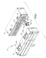
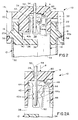
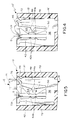
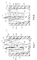
- Connecteur électrique (10, 10') qui comprend un boítier diélectrique (12, 70) comportant un conduit (22, 72) de réception de borne, une borne autodénudante (16, 16') reçue dans le conduit et définissant une embouchure destinée à accepter un fil isolé (52) à raccorder, le fil (52) comprenant un conducteur électrique (52b) entouré d'une gaine isolante (52a), et la borne (16, 16') comprenant une section de raccordement (32) qui est globalement plate dans un plan qui coïncide avec l'axe longitudinal (54) du fil isolé (52) et qui comprend au moins une partie rigide (48), une partie intermédiaire (38) et une partie pouvant fléchir (44) pour déplacer l'isolant (52a) et contacter le conducteur (52b) lors de l'application d'une force (A, E), globalement vers l'intérieur et parallèlement à l'axe longitudinal (54), sur la borne ;
caractérisé en ce que :
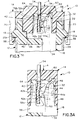
la partie pouvant fléchir (44) est reliée à la partie rigide (48) par l'intermédiaire d'une bande déformable (46) et à la partie intermédiaire (38) par l'intermédiaire d'une zone formant col déformable (50), lesquelles sont agencées et configurées de façon à déplacer ladite partie pouvant fléchir (44) principalement transversalement (C) à l'axe longitudinal lorsque l'on applique ladite force parallèle (A, E) à ladite partie pouvant fléchir (44). - Connecteur électrique selon la revendication 1, dans lequel ladite bande déformable (46) est ondulée, en forme de U, avec un évidement (62) faisant face vers l'extérieur, et dans lequel ladite force parallèle (A, E) est appliquée sur ladite bande (46) par l'intermédiaire d'un bossage de déviation (60, 76) entrant dans ledit évidement (62) de sorte que ladite bande (46) se déforme avec une composante d'extension latérale.
- Connecteur électrique selon la revendication 1 ou 2, dans lequel la section de raccordement (32) de la borne (16, 16') comprend également une partie fixe (42) faisant face à ladite partie pouvant fléchir (44) et définissant, entre elles, ladite embouchure destinée à accepter le fil isolé (52).
- Connecteur électrique selon la revendication 3, dans lequel au moins l'une desdites parties fixe et pouvant fléchir (42, 44) comprend des dents de dénudage (42a, 44a) qui sont dirigées dans ladite embouchure.
- Connecteur électrique selon l'une quelconque des revendications 1 à 4, dans lequel ledit boítier diélectrique (12) est un boítier en deux parties comprenant une partie embase (12) et une partie de recouvrement (14), la partie embase (12) logeant la borne (16) et la partie de recouvrement (14) coopérant avec la partie fléchissante (44) en réponse au déplacement relatif entre les parties de boítier (12, 14) lorsque l'on applique ladite force (A).
- Connecteur électrique selon la revendication 5, dans lequel ladite partie de recouvrement (14) comprend un conduit (24) de réception de fil, aligné avec ledit conduit (22) de réception de borne.
- Borne autodénudante (16, 16') destinée à raccorder un fil isolé (52) comportant un conducteur électrique (52b) entouré d'une gaine isolante (52a) , comprenant une section de raccordement (32) qui est globalement plate dans un plan qui coïncide avec l'axe longitudinal (54) du fil isolé, et qui comprend au moins une partie rigide (48), une partie intermédiaire (38) et une partie pouvant fléchir (44) faisant face à une embouchure destinée à accepter le fil isolé (52), ladite partie pouvant fléchir (44) déplaçant l'isolant (52a) et contactant le conducteur (52b) lors de l'application d'une force (A, E), globalement parallèlement à l'axe longitudinal (54), sur la borne ;
caractérisée en ce que :
la partie pouvant fléchir (44) est reliée à la partie rigide (48) par l'intermédiaire d'une bande déformable (46) et à la partie intermédiaire (38) par l'intermédiaire d'une zone formant col déformable (50) qui sont agencées et configurées de façon à déplacer ladite partie pouvant fléchir (44) principalement transversalement (C) à l'axe longitudinal lorsque l'on applique ladite force parallèle (A, E) sur ladite partie pouvant fléchir (44). - Borne autodénudante selon la revendication 7, dans laquelle ladite bande déformable (46) est ondulée, en forme de U, avec un évidement (62) faisant face vers l'extérieur, et dans laquelle ladite force parallèle (A, E) est appliquée sur ladite bande (46) par l'intermédiaire d'un bossage de déviation (60, 76) entrant dans ledit évidement (62) de sorte que ladite bande (46) se déforme avec une composante d'extension latérale.
- Borne autodénudante selon la revendication 7 ou 8, dans laquelle la section de raccordement (32) de la borne (16, 16') comprend également une partie fixe (42) faisant face à ladite partie pouvant fléchir (44) et définissant, entre elles, ladite embouchure destinée à accepter le fil isolé.
- Borne autodénudante selon la revendication 9, dans laquelle au moins l'une desdites parties fixe et pouvant fléchir (42, 44) comprend des dents de dénudage (42a, 44a) qui sont dirigées dans ladite embouchure.
Priority Applications (7)
| Application Number | Priority Date | Filing Date | Title |
|---|---|---|---|
| DE69317049T DE69317049T2 (de) | 1993-09-18 | 1993-09-18 | Flacher Schneidklemmkontakt für elektrische Verbinder |
| EP93115041A EP0644609B1 (fr) | 1993-09-18 | 1993-09-18 | Organe de contact plat à déplacement d'isolation pour connecteurs électriques |
| US08/280,897 US5417581A (en) | 1993-09-18 | 1994-07-27 | Flat insulation displacement terminal for electrical connectors |
| TW083107163A TW255063B (fr) | 1993-09-18 | 1994-08-04 | |
| JP6247254A JPH0794216A (ja) | 1993-09-18 | 1994-09-14 | 電気コネクタ用のフラットな絶縁被覆 切り込み端子 |
| KR1019940023805A KR0148396B1 (ko) | 1993-09-18 | 1994-09-17 | 납작한 전기 커넥터용 절연 변위 단자 |
| JP1997005596U JP3044378U (ja) | 1993-09-18 | 1997-06-13 | 電気コネクタ用のフラットな絶縁被覆切り込み端子 |
Applications Claiming Priority (1)
| Application Number | Priority Date | Filing Date | Title |
|---|---|---|---|
| EP93115041A EP0644609B1 (fr) | 1993-09-18 | 1993-09-18 | Organe de contact plat à déplacement d'isolation pour connecteurs électriques |
Publications (2)
| Publication Number | Publication Date |
|---|---|
| EP0644609A1 EP0644609A1 (fr) | 1995-03-22 |
| EP0644609B1 true EP0644609B1 (fr) | 1998-02-18 |
Family
ID=8213277
Family Applications (1)
| Application Number | Title | Priority Date | Filing Date |
|---|---|---|---|
| EP93115041A Expired - Lifetime EP0644609B1 (fr) | 1993-09-18 | 1993-09-18 | Organe de contact plat à déplacement d'isolation pour connecteurs électriques |
Country Status (6)
| Country | Link |
|---|---|
| US (1) | US5417581A (fr) |
| EP (1) | EP0644609B1 (fr) |
| JP (2) | JPH0794216A (fr) |
| KR (1) | KR0148396B1 (fr) |
| DE (1) | DE69317049T2 (fr) |
| TW (1) | TW255063B (fr) |
Families Citing this family (12)
| Publication number | Priority date | Publication date | Assignee | Title |
|---|---|---|---|---|
| FR2723474B1 (fr) * | 1994-08-04 | 1997-01-03 | Entrelec Sa | Connexion auto-denudante a action rapide |
| DE4437022C1 (de) * | 1994-10-08 | 1996-02-22 | Krone Ag | Anschlußelement |
| DE19652422C1 (de) * | 1996-12-09 | 1998-04-23 | Krone Ag | Anschlußleiste |
| US6000951A (en) * | 1997-03-18 | 1999-12-14 | Prince Corporation | Electrical ribbon wire connectors |
| US6068504A (en) * | 1998-09-08 | 2000-05-30 | Molex Incorporated | Selective termination connector assembly |
| JP4269031B2 (ja) * | 1999-03-03 | 2009-05-27 | モレックス インコーポレイテド | 細線同軸ケーブルの接続方法およびコネクタ |
| US6447326B1 (en) | 2000-08-09 | 2002-09-10 | Panduit Corp. | Patch cord connector |
| JP3520986B2 (ja) * | 2000-12-08 | 2004-04-19 | タイコエレクトロニクスアンプ株式会社 | 電気コネクタ |
| US6966793B2 (en) * | 2003-05-22 | 2005-11-22 | Tyco Electronics Corporation | Electrical connector having a cover for registering cables with contacts |
| KR100868567B1 (ko) * | 2005-06-30 | 2008-11-13 | 주식회사 히타치엘지 데이터 스토리지 코리아 | 터미널 및 이를 사용한 커넥터 |
| CN201142451Y (zh) * | 2007-12-12 | 2008-10-29 | 富士康(昆山)电脑接插件有限公司 | 电连接器组件及其电连接器与壳体 |
| US10950998B2 (en) * | 2019-03-11 | 2021-03-16 | Avx Corporation | Wire guide for insulation displacement contact (IDC) |
Family Cites Families (13)
| Publication number | Priority date | Publication date | Assignee | Title |
|---|---|---|---|---|
| GB1407311A (en) * | 1972-09-11 | 1975-09-24 | Amp Inc | Electrical connector |
| US3825881A (en) * | 1972-12-29 | 1974-07-23 | Burndy Corp | Termination device for flat electrical conductors |
| GB1425477A (en) * | 1973-03-23 | 1976-02-18 | Cannon Electric Great Britain | Connectors |
| US3937549A (en) * | 1974-06-18 | 1976-02-10 | Amp Incorporated | Strimp |
| US4258973A (en) * | 1979-06-07 | 1981-03-31 | Amp Incorporated | Connecting means having kinematic conductor-contacting portions |
| GB2124041B (en) * | 1982-07-23 | 1985-11-27 | Molex Inc | Insulation displacement terminal for an electrical connector and environmental sealing means therefor |
| US4522460A (en) * | 1983-12-15 | 1985-06-11 | Amp Incorporated | Connecting means for closely spaced conductors |
| US4752237A (en) * | 1987-07-27 | 1988-06-21 | Amp Incorporated | Solderless connector |
| US4790771A (en) * | 1987-09-23 | 1988-12-13 | Amp Incorporated | Wire trap terminal |
| US4955816A (en) * | 1989-04-20 | 1990-09-11 | Molex Incorporated | Electrical connector system and insulation displacement terminals therefor |
| US4946406A (en) * | 1989-05-19 | 1990-08-07 | Amp Incorporated | Electrical connector which requires no application tool |
| EP0474113B1 (fr) * | 1990-09-01 | 1995-09-20 | Molex Incorporated | Dispositif de connexion pour câbles multifilaires |
| US5125851A (en) * | 1991-09-23 | 1992-06-30 | Molex Incorporated | Insulation displacement terminal for an electrical connector |
-
1993
- 1993-09-18 DE DE69317049T patent/DE69317049T2/de not_active Expired - Fee Related
- 1993-09-18 EP EP93115041A patent/EP0644609B1/fr not_active Expired - Lifetime
-
1994
- 1994-07-27 US US08/280,897 patent/US5417581A/en not_active Expired - Fee Related
- 1994-08-04 TW TW083107163A patent/TW255063B/zh active
- 1994-09-14 JP JP6247254A patent/JPH0794216A/ja active Pending
- 1994-09-17 KR KR1019940023805A patent/KR0148396B1/ko not_active IP Right Cessation
-
1997
- 1997-06-13 JP JP1997005596U patent/JP3044378U/ja not_active Expired - Lifetime
Also Published As
| Publication number | Publication date |
|---|---|
| DE69317049D1 (de) | 1998-03-26 |
| TW255063B (fr) | 1995-08-21 |
| JPH0794216A (ja) | 1995-04-07 |
| KR950010174A (ko) | 1995-04-26 |
| DE69317049T2 (de) | 1998-07-23 |
| US5417581A (en) | 1995-05-23 |
| KR0148396B1 (ko) | 1998-11-16 |
| EP0644609A1 (fr) | 1995-03-22 |
| JP3044378U (ja) | 1997-12-22 |
Similar Documents
| Publication | Publication Date | Title |
|---|---|---|
| CA1068363A (fr) | Connecteur electrique a dispositif de depouillage d'isolant | |
| US5445538A (en) | Electrical connector strain relief | |
| US4556275A (en) | Electrical panelboard connector | |
| JPH11508723A (ja) | パッチコード組立体 | |
| EP0644609B1 (fr) | Organe de contact plat à déplacement d'isolation pour connecteurs électriques | |
| US4512619A (en) | Insulation displacement terminal for an electrical connector _and environmental sealing means therefor | |
| US5061196A (en) | Selective shorting of plug pins/socket contacts in an electrical connector | |
| US5133672A (en) | Insulation displacement terminal | |
| US5564940A (en) | Electrical connector having a conductor holding block | |
| JPH0371741B2 (fr) | ||
| WO2005071799A1 (fr) | Connecteur electrique comprenant une borne amelioree | |
| EP0109297B1 (fr) | Eléments de contacts électriques et d'assemblages de connecteurs électriques | |
| US7112105B2 (en) | Cable assembly having power contacts | |
| JP2965210B2 (ja) | 電気コネクタ | |
| US5114362A (en) | High density electrical connector and method of making a high density electrical connector | |
| US4946406A (en) | Electrical connector which requires no application tool | |
| EP0722197B1 (fr) | Contact à déplacement d'isolant pour des fils de tailles différentes | |
| US4486064A (en) | Power interface connector | |
| EP0102156A2 (fr) | Borne de raccordement à déplacement d'isolant pour un connecteur électrique et moyens assurant son étanchéité par rapport au milieu environnant | |
| US5252094A (en) | Electrical connector with improved terminal retention | |
| EP0598940B1 (fr) | Dispositif de connexion électrique à déplacement d'isolant | |
| US6672913B1 (en) | Plug connector and method for manufacturing the same | |
| EP0534276B1 (fr) | Organe de contact à déplacement d'isolation pour connecteur électrique | |
| EP0152690B1 (fr) | Assemblage pour connecteur multi-conducteur à déplacement d'isolant | |
| EP0235193B1 (fr) | Fiche de raccordement electrique |
Legal Events
| Date | Code | Title | Description |
|---|---|---|---|
| PUAI | Public reference made under article 153(3) epc to a published international application that has entered the european phase |
Free format text: ORIGINAL CODE: 0009012 |
|
| AK | Designated contracting states |
Kind code of ref document: A1 Designated state(s): DE ES FR GB IT SE |
|
| 17P | Request for examination filed |
Effective date: 19950906 |
|
| 17Q | First examination report despatched |
Effective date: 19960826 |
|
| GRAG | Despatch of communication of intention to grant |
Free format text: ORIGINAL CODE: EPIDOS AGRA |
|
| GRAG | Despatch of communication of intention to grant |
Free format text: ORIGINAL CODE: EPIDOS AGRA |
|
| GRAH | Despatch of communication of intention to grant a patent |
Free format text: ORIGINAL CODE: EPIDOS IGRA |
|
| ITF | It: translation for a ep patent filed |
Owner name: DE DOMINICIS & MAYER S.R.L. |
|
| GRAH | Despatch of communication of intention to grant a patent |
Free format text: ORIGINAL CODE: EPIDOS IGRA |
|
| GRAA | (expected) grant |
Free format text: ORIGINAL CODE: 0009210 |
|
| AK | Designated contracting states |
Kind code of ref document: B1 Designated state(s): DE ES FR GB IT SE |
|
| PG25 | Lapsed in a contracting state [announced via postgrant information from national office to epo] |
Ref country code: ES Free format text: THE PATENT HAS BEEN ANNULLED BY A DECISION OF A NATIONAL AUTHORITY Effective date: 19980218 |
|
| REF | Corresponds to: |
Ref document number: 69317049 Country of ref document: DE Date of ref document: 19980326 |
|
| ET | Fr: translation filed | ||
| PLBE | No opposition filed within time limit |
Free format text: ORIGINAL CODE: 0009261 |
|
| STAA | Information on the status of an ep patent application or granted ep patent |
Free format text: STATUS: NO OPPOSITION FILED WITHIN TIME LIMIT |
|
| 26N | No opposition filed | ||
| PGFP | Annual fee paid to national office [announced via postgrant information from national office to epo] |
Ref country code: GB Payment date: 20000807 Year of fee payment: 8 |
|
| PGFP | Annual fee paid to national office [announced via postgrant information from national office to epo] |
Ref country code: SE Payment date: 20000901 Year of fee payment: 8 |
|
| PGFP | Annual fee paid to national office [announced via postgrant information from national office to epo] |
Ref country code: FR Payment date: 20000905 Year of fee payment: 8 |
|
| PGFP | Annual fee paid to national office [announced via postgrant information from national office to epo] |
Ref country code: DE Payment date: 20000928 Year of fee payment: 8 |
|
| PG25 | Lapsed in a contracting state [announced via postgrant information from national office to epo] |
Ref country code: GB Free format text: LAPSE BECAUSE OF NON-PAYMENT OF DUE FEES Effective date: 20010918 |
|
| PG25 | Lapsed in a contracting state [announced via postgrant information from national office to epo] |
Ref country code: SE Free format text: LAPSE BECAUSE OF NON-PAYMENT OF DUE FEES Effective date: 20010919 |
|
| REG | Reference to a national code |
Ref country code: GB Ref legal event code: IF02 |
|
| PG25 | Lapsed in a contracting state [announced via postgrant information from national office to epo] |
Ref country code: DE Free format text: LAPSE BECAUSE OF NON-PAYMENT OF DUE FEES Effective date: 20020501 |
|
| EUG | Se: european patent has lapsed |
Ref document number: 93115041.1 |
|
| GBPC | Gb: european patent ceased through non-payment of renewal fee |
Effective date: 20010918 |
|
| PG25 | Lapsed in a contracting state [announced via postgrant information from national office to epo] |
Ref country code: FR Free format text: LAPSE BECAUSE OF NON-PAYMENT OF DUE FEES Effective date: 20020531 |
|
| REG | Reference to a national code |
Ref country code: FR Ref legal event code: ST |
|
| PG25 | Lapsed in a contracting state [announced via postgrant information from national office to epo] |
Ref country code: IT Free format text: LAPSE BECAUSE OF NON-PAYMENT OF DUE FEES;WARNING: LAPSES OF ITALIAN PATENTS WITH EFFECTIVE DATE BEFORE 2007 MAY HAVE OCCURRED AT ANY TIME BEFORE 2007. THE CORRECT EFFECTIVE DATE MAY BE DIFFERENT FROM THE ONE RECORDED. Effective date: 20050918 |