EP0644609B1 - Flacher Schneidklemmkontakt für elektrische Verbinder - Google Patents
Flacher Schneidklemmkontakt für elektrische Verbinder Download PDFInfo
- Publication number
- EP0644609B1 EP0644609B1 EP93115041A EP93115041A EP0644609B1 EP 0644609 B1 EP0644609 B1 EP 0644609B1 EP 93115041 A EP93115041 A EP 93115041A EP 93115041 A EP93115041 A EP 93115041A EP 0644609 B1 EP0644609 B1 EP 0644609B1
- Authority
- EP
- European Patent Office
- Prior art keywords
- terminal
- insulation
- deflectable
- insulated wire
- web
- Prior art date
- Legal status (The legal status is an assumption and is not a legal conclusion. Google has not performed a legal analysis and makes no representation as to the accuracy of the status listed.)
- Expired - Lifetime
Links
Images
Classifications
-
- H—ELECTRICITY
- H01—ELECTRIC ELEMENTS
- H01R—ELECTRICALLY-CONDUCTIVE CONNECTIONS; STRUCTURAL ASSOCIATIONS OF A PLURALITY OF MUTUALLY-INSULATED ELECTRICAL CONNECTING ELEMENTS; COUPLING DEVICES; CURRENT COLLECTORS
- H01R4/00—Electrically-conductive connections between two or more conductive members in direct contact, i.e. touching one another; Means for effecting or maintaining such contact; Electrically-conductive connections having two or more spaced connecting locations for conductors and using contact members penetrating insulation
- H01R4/24—Connections using contact members penetrating or cutting insulation or cable strands
- H01R4/2495—Insulation penetration combined with permanent deformation of the contact member, e.g. crimping
-
- H—ELECTRICITY
- H01—ELECTRIC ELEMENTS
- H01R—ELECTRICALLY-CONDUCTIVE CONNECTIONS; STRUCTURAL ASSOCIATIONS OF A PLURALITY OF MUTUALLY-INSULATED ELECTRICAL CONNECTING ELEMENTS; COUPLING DEVICES; CURRENT COLLECTORS
- H01R12/00—Structural associations of a plurality of mutually-insulated electrical connecting elements, specially adapted for printed circuits, e.g. printed circuit boards [PCB], flat or ribbon cables, or like generally planar structures, e.g. terminal strips, terminal blocks; Coupling devices specially adapted for printed circuits, flat or ribbon cables, or like generally planar structures; Terminals specially adapted for contact with, or insertion into, printed circuits, flat or ribbon cables, or like generally planar structures
- H01R12/50—Fixed connections
- H01R12/59—Fixed connections for flexible printed circuits, flat or ribbon cables or like structures
- H01R12/65—Fixed connections for flexible printed circuits, flat or ribbon cables or like structures characterised by the terminal
- H01R12/67—Fixed connections for flexible printed circuits, flat or ribbon cables or like structures characterised by the terminal insulation penetrating terminals
-
- H—ELECTRICITY
- H01—ELECTRIC ELEMENTS
- H01R—ELECTRICALLY-CONDUCTIVE CONNECTIONS; STRUCTURAL ASSOCIATIONS OF A PLURALITY OF MUTUALLY-INSULATED ELECTRICAL CONNECTING ELEMENTS; COUPLING DEVICES; CURRENT COLLECTORS
- H01R4/00—Electrically-conductive connections between two or more conductive members in direct contact, i.e. touching one another; Means for effecting or maintaining such contact; Electrically-conductive connections having two or more spaced connecting locations for conductors and using contact members penetrating insulation
- H01R4/24—Connections using contact members penetrating or cutting insulation or cable strands
- H01R4/2416—Connections using contact members penetrating or cutting insulation or cable strands the contact members having insulation-cutting edges, e.g. of tuning fork type
- H01R4/242—Connections using contact members penetrating or cutting insulation or cable strands the contact members having insulation-cutting edges, e.g. of tuning fork type the contact members being plates having a single slot
- H01R4/2425—Flat plates, e.g. multi-layered flat plates
- H01R4/2429—Flat plates, e.g. multi-layered flat plates mounted in an insulating base
- H01R4/2433—Flat plates, e.g. multi-layered flat plates mounted in an insulating base one part of the base being movable to push the cable into the slot
Definitions
- This invention relates to an electrical connector according to the preamble of claim 1 and to an insulation displacement terminal according to the preamble of claim 7.
- Electrical connectors have become widely accepted as a preferred means for interconnecting the circuitry components of electrically operated products and equipment. In such applications, providing for easy connection and disconnection of cable or wire through the use of connectors permits convenience of assembly and maintenance as well as versatility in design.
- Connectors in current use are of diverse construction.
- a common arrangement includes a dielectric housing fitted with a plurality of stamped and formed conductive terminals to which insulated multiconductor cable or wiring may be electrically connected.
- Numerous terminal configurations likewise are available, suited to the specific requirement of the application.
- a preferred terminal in many applications is one which has the capability of establishing electrical contact with the conductors of the cable by displacement of the insulative coating of the conductors, obviating the need to perform the separate step of stripping the insulative coating.
- a wide variety of insulation displacement terminals are known in the art. Generally, these terminals provide a narrow slot which receives an insulation covered wire, severs the insulation covering of the wire in the process, and establishes, automatically, an electrical connection between the terminal and the central core of the wire. This is contrasted with the self-piercing type of terminals which usually have sections in the form of teeth that pierce the insulation and engage the metallic core when the terminal is clinched or secured to the wire. When piercing the insulation, the teeth, in essence, also displace the insulation in order to engage the core of the wire.
- One type of self-piercing terminal is a flat, stamped metal terminal commonly used to terminate electrical wires on a low pitch spacing, such as in a Western Electric Company modular phone plug, as is shown in U.S. Patent No. 3,954,320, dated May 4, 1976.
- Such terminals have been used primarily with electrical wires having stranded conductive cores.
- the terminals require terminating forces applied normal to the longitudinal axis of the insulated wire, and the connector relies on the dielectric or plastic housing to maintain contact pressure on the terminals after termination.
- Such flat terminal connectors cause problems in many applications because the terminating forces must be applied transversely of the length of the insulated wires, which is quite limiting and is particularly limiting where multiple rows of circuit connections are desired.
- the present invention is directed to providing a flat, insulation piercing type terminal which is terminated by the application of a force generally parallel to the axis of the insulated wire.
- the terminal of the invention is deformed during the termination process to maintain contact pressure after termination so as not to rely on the connector housing to maintain constant pressure, and the terminal is equally applicable with solid or stranded conductive cores of the insulated wire.
- a connector and terminal according to the preamble of claims 1 and 7 is known from EP-A-0 145 315.
- the terminal is U-shaped and has a parallelogram-like structure to move the deflectable portion onto the rigid portion. Such movement includes a shifting component along the rigid portion which is undesirable.
- An object, therefore, of the invention is to provide a new and improved insulation displacement electrical connector and terminal therefor. wherein the insulation piercing movement is transversely to the extension of the wire to be terminated.
- an electrical connector in the exemplary embodiment of the invention, includes a dielectric housing having at least one terminal-receiving passageway.
- An insulation displacement terminal is received in the passageway for terminating an insulated wire extending into the passageway.
- the wire includes an electrical conductor with a sheath of insulation thereabout.
- the terminal includes a terminating section deflectable for displacing the insulation and engaging the conductor.
- the terminating section of the terminal is generally flat in a plane coincident with the longitudinal axis of the insulated wire. At least a portion of the terminating section is deflectable upon the application of a force on the terminal generally parallel to the longitudinal axis. According to another aspect of the invention, the terminal, or at least a portion thereof, is permanently deformable into an insulation-displacing condition with the insulated wire.
- the terminating section of the terminal includes a fixed portion and a deflectable portion defining a mouth therebetween for accepting the insulated wire. At least one of the portions of the terminating section include inwardly directed insulation displacing teeth.
- the dielectric housing is a two-part housing including a base part and a cover part.
- the base part mounts the terminal, and the cover part engages the terminal for deflecting the terminating section in response to relative movement between the housing parts generally parallel to the longitudinal axis of the insulated wire.
- the cover part includes a wire-receiving passage aligned with the terminal-receiving passageway.
- a one-piece housing mounts the terminal, and a separate tool terminates the terminal.
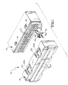
- Figures 1-3A show an embodiment of an electrical connector incorporating a two-part housing
- Figures 4-7 show an embodiment of the invention incorporated in a one-piece connector housing.
- the primary difference between the two embodiments is that the two-part connector housing of Figures 1-3A is used to deform the insulation displacement terminal, whereas a terminating tool is used in the embodiment of Figures 4-7.
- the unique, deformable flat terminal of the invention is the same in both embodiments.
- an electrical connector generally designated 10
- a two-part housing including a base part, generally designated 12, and a cover part, generally designated 14.
- Base part 12 mounts a plurality of terminals, generally designated 16, and cover part 14 is effective to engage the terminals and deform the terminals into insulation-displacing condition with respect to a plurality of insulated electrical wires, as will be described hereinafter.
- base part 12 of the two-part housing includes a pair of stepped latch bosses 18 on each opposite longitudinal side thereof.
- Cover part 14 includes a pair of U-shaped latch arms 20 on each longitudinal side thereof for latchingly engaging latch bosses 18. Each latch arm 20 has a latch shoulder 20a defined on the inside of the U-shaped configuration thereof.
- base part 12 has a row of terminal-receiving passageways 22 each adapted for receiving one of the terminals 16.
- Cover part 14 includes a plurality of wire-receiving passages 24 which are aligned with terminal-receiving passageways 22 when the two parts of the housing are engaged.
- terminal-receiving passageways 22 have enlarged, rounded center areas 22a of a size similar to wire-receiving passages 24.
- Cover part 14 of the connector housing is unitarily molded of dielectric material such as plastic or the like. Therefore, latch arms 20 are resiliently flexible for snappingly engaging latch bosses 18.
- base part 12 of the connector housing includes a unitarily molded plastic body 26 substantially surrounded by a shield 28 of conductive material, such as metal. The shield defines a mating cavity 30 for receiving a complementary electrical connector, as described hereinafter.
- each terminal 16 includes a terminating section, generally designated 32, and a blade section 34 which projects through a hole 36 (Fig. 2) in body 26 and into mating cavity 30 within shield 28.
- the terminal blade forms a male contact for engaging a female contact portion of a terminal in the mating connector which is inserted into cavity 30.
- the terminal further includes an intermediate body section 38 press-fit into an enlarged area 40 of each terminal-receiving passageway 22 in body 26 of the base part of the connector housing.
- Terminating section 32 of each terminal 16 includes a fixed portion 42 and a deflectable portion 44 which, in turn, is connected by a deformable web 46 to a rigid portion 48 solidly joined to body portion 38.
- Deflectable portion 44 is joined to body portion 38 by a narrow deformable neck area 50.
- each of fixed portion 42 and deflectable portion 44 include teeth 42a and 44a, respectively, for piercing and, therefore, displacing the insulation of an electrical wire 52 which defines a longitudinal axis 54 thereof.
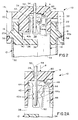
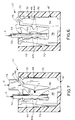
- FIGS 2 and 2A show electrical connector 10 in a pre-terminating condition wherein cover part 14 of the two-part connector housing has its latch arms 20 snappingly engaging a first step 56 of each latch boss 18.
- electrical wire 52 is readily inserted through a respective wire-receiving passage 24 in cover part 14 in the direction of arrow "A", and to a position between fixed portion 42 and deflectable portion 44 of terminating section 32 of the respective terminal 16.
- cover part 14 of the two-part connector housing is shown having been moved in the direction of arrow "B", whereby latch shoulders 20a of latch arms 20 have engaged second steps 58 of latch bosses 18.
- a deflecting boss 60 on the inside of cover part 14 has engaged within a recess 62 adjacent deformable web 46 of terminating section 32 of terminal 16.
- fixed portion 42 of the terminating section rigidly abuts the inside of cover part 14, as at 64. Therefore, fixed portion 42 remains stationary or fixed at all times during termination.
- deflectable portion 44 can be seen deflected in the direction of arrow "C" toward fixed portion 42, as the terminating section of the terminal deforms at deformable web 46 and neck area 50. It also can be seen that teeth 44a of deflectable portion 44 have been driven through insulation 52a of insulated wire 52 and into contact with a conductor or core 52b of the wire. Teeth 42a of fixed portion 42 also have been driven through the insulation into contact with the conductor.
- cover part 14 is shown in Figures 3 and 3A in a latched condition with respect to base part 12 of the connector housing, with terminating section 32 in its deformed condition, the cover part is not necessary to maintain the deformed or insulation-displacing condition of the terminal. That is because the terminal is stamped in a flat configuration and is disposed within the connector in a plane coincident with longitudinal axis 54 of insulated wire 52.
- deformable web 46 and neck area 50 deform in a direction coplanar with the plane of the metal material which forms the terminal or at least the terminating section thereof. This is in contrast to deflecting the metal material transverse to its plane which would result in a resilient or "spring-back" condition.
- the deflected portions i.e. deformable web 46 and neck area 50
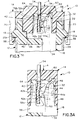
- Figures 4-7 show an alternate embodiment of the invention wherein an electrical connector, generally designated 10', is shown to include a one-part housing 70 having a plurality of terminal-receiving passageways 72 with enlarged areas 72a for receiving an insulated wire 52 in the direction of arrow "D" (Fig. 4). Only one passageway 72 is shown in the drawings for receiving a respective one of terminals 16' which is very similarly configured to terminal 16 in Figures 1-3A. Therefore, like numerals have been applied to like components or portions of terminal 16' corresponding to similar portions of terminal 16 described above.
- Figure 5 shows a terminating tool 74 having a distal end provided with a deflecting boss 76 which corresponds to deflecting boss 60 inside cover part 14 as described above.
- Figure 4 shows insulation displacement section 32 of terminal 16' in an unstressed or non-terminating condition.
- Figure 5 shows tool 74 having been forced downwardly in the direction of arrow "E” to deform terminating section 32 at deformable web 46 and neck area 50, as described above, to drive deflecting portion 44 and its teeth 44a in the direction of arrow "C".
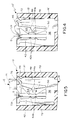
- Figures 6 and 7 are substantially identical to Figures 4 and 5, except that electrical wire 52 has been inserted between deflectable portion 44 and fixed portion 42 of terminating section 32 of the terminal to show the insulation displacement effect in connector 10' and how the action is substantially identical to that described above in relation to connector 10 in Figures 2-3A.
- fixed portion 42 Is not rigidly backed by the housing in an area corresponding to area 64 in the embodiment illustrated in Figure 3.
- the base of fixed portion 42 where it is joined to body portion 38 is much wider than either neck area 50 or deformable web 46 and, therefore, deflectable portion 44 will be moved while fixed portion 42 experiences little movement.
- terminating tool 74 Fig. 7
- terminating section 32 i.e. deformable web 46 and neck area 50
- deflectable portion 44 of the terminal fully terminated to insulated wire 52.
Claims (10)
- Elektrischer Verbinder (10,10') mit folgenden Merkmalen:dadurch gekennzeichnet, daßein dielektrisches Gehäuse (12,70) mit einem Klemmen aufnehmenden Durchgang (22,72);eine die Isolierung durchdringende Schneidklemme (15,16'), die in dem Durchgang aufgenommen wird und ein Maul zum Aufnehmen eines anzuschließenden isolierten Drahtes (52) bildet;der Draht (52) umfaßt einen elektrischen Leiter (52b) mit einer Isolation (52a);die Schneidklemme umfaßt (16,16') einen Anschlußabschnitt (32), der in einer die Längsachse (54) des isolierten Drahtes enthaltenden Ebene im wesentlichen flach ist sowie wenigstens ein starres Teil (48), ein Zwischenteil (38) und ein abbiegbares Teil (44) zum Durchdringen der Isolation (52a) und zur Anlage an dem Leiter (52b) aufweist, und zwar beim Anlegen einer Kraft an die Klemme, die generell innen und parallel (A,E) zur Längsachse (54) verläuft,
das abbiegbare Teil (44) mit dem starren Teil (48) über einen verformbaren Steg (46) und mit dem Zwischenteil (38) über einen verformbaren Halsbereich (50) verbunden ist, die so angeordnet und konfiguriert sind, daß das abbiegbare Teil (44) im wesentlichen quer (C) zur Längsachse bewegbar ist, wenn die parallele Kraft (A,E) an das abbiegbare Teil (44) angelegt wird. - Elektrischer Verbinder nach Anspruch 1, dadurch gekennzeichnet, daß der verformbare Steg (46) U-förmigwellenförmig ist, wobei eine Aussparung (62) nach außen schaut und die parallele Kraft (A,E) auf einen Steg (46) wirkt, und zwar über einen Ablenkvorsprung (60,76), der in die Aussparung (62) eindringt, um den Steg mit einer seitlichen Verschiebekomponente zu verformen.
- Elektrischer Verbinder nach den Ansprüchen 1 oder 2, dadurch gekennzeichnet, daß der Anschlußabschnitt (32) der Klemme (16,16') desweiteren einen fixierten Abschnitt (42) umfaßt, welcher dem abbiegbaren Teil (44) gegenüberliegt und diese Teile das Maul zum Aufnehmen des isolierten Drahtes (52) bilden.
- Elektrischer Steckverbinder nach Anspruch 3, dadurch gekennzeichnet, daß wenigstens eines der fixierten und abbiegbaren Teile (42,44) Isolationsdurchdringungszähne (72a,74a) umfaßt, die in das Maul hineinragen.
- Elektrischer Steckverbinder nach einem der Ansprüche 1 bis 4, dadurch gekennzeichnet, daß das dielektrische Gehäuse (12) ein zweiteiliges Gehäuse ist und ein Unterteil (12) sowie ein Oberteil (14) umfaßt, wobei das Unterteil (12) die Klemme (16) aufnimmt und das Oberteil (14) am abbiegbaren Teil (44) angreift, wenn die Kraft (A) angelegt wird und sich die Gehäuseteile (12,14) gegeneinander bewegen.
- Elektrischer Steckverbinder nach Anspruch 5, dadurch gekennzeichnet, daß das Oberteil (14) einen Draht aufnehmenden Durchgang (24) umfaßt, der zu dem Klemmen aufnehmenden Durchgang (22) ausgerichtet ist.
- Eine Isolationsdurchdringungsklemme (16,16') zum Anschließen eines isolierten Drahtes (52), der einen elektrischen Leiter (52b) und eine Isolation (52a) umfaßt, mit folgenden Merkmalen:
ein Anschlußabschnitt (32), der in einer die Längsachse (54) des isolierten Drahtes enthaltenden Ebene im wesentlichen flach ist sowie wenigstens ein starres Teil (48), ein Zwischenteil (38) und ein abbiegbares Teil (44) aufweist, die einem Maul zum Aufnehmen des isolierten Drahtes (52) gegenüberstehen, wobei das abbiegbare Teil (44) die Isolation (52a) durchdringt und den Leiter (52b) beim Anlegen einer Kraft an die Klemme, die im wesentlichen parallel (A,E) zur Längsachse (54) gerichtet ist, erfaßt, dadurch gekennzeichnet, daß das abbiegbare Teil (44) mit dem starren Teil (48) über einen deformierbaren Steg (46) und mit dem Zwischenteil (38) über einen deformierbaren Halsbereich (50) verbunden ist, die so angeordnet und konfiguriert sind, daß das abbiegbare Teil (44) im wesentlichen quer (C) zur Längsachse bewegbar ist, wenn die parallele Kraft (A,E) an das abbiegbare Teil (44) angelegt wird. - Die Isolationsdurchdringungsklemme nach Anspruch 7, dadurch gekennzeichnet, daß der deformierbare Steg (45) U-förmig-wellenförmig ist, wobei eine Aussparung (62) nach außen schaut und die parallele Kraft (A,E) auf den Steg (46) wirkt und zwar über einen Ablenkvorsprung (60,76), der in die Aussparung (62) eindringt, um den Steg mit einer seitlichen Verschiebekomponente zu verformen.
- Die Isolationsdurchdringungsklemme nach Anspruch 7 oder 8, dadurch gekennzeichnet, daß der Anschlußabschnitt (32) der Klemme (16,16') desweiteren einen fixierten Abschnitt (42) umfaßt, welcher dem abbiegbaren Teil (44) gegenüberliegt und diese Teile das Maul zum Aufnehmen des isolierten Drahtes (52) bilden.
- Die Isolationsdurchdringungsklemme nach Anspruch 9, dadurch gekennzeichnet, daß wenigstens eines der fixierten und abbiegbaren Teile (42,44) Isolationsdurchdringungszähne (72a,74a) umfaßt, die in das Maul hineinragen.
Priority Applications (7)
| Application Number | Priority Date | Filing Date | Title |
|---|---|---|---|
| EP93115041A EP0644609B1 (de) | 1993-09-18 | 1993-09-18 | Flacher Schneidklemmkontakt für elektrische Verbinder |
| DE69317049T DE69317049T2 (de) | 1993-09-18 | 1993-09-18 | Flacher Schneidklemmkontakt für elektrische Verbinder |
| US08/280,897 US5417581A (en) | 1993-09-18 | 1994-07-27 | Flat insulation displacement terminal for electrical connectors |
| TW083107163A TW255063B (de) | 1993-09-18 | 1994-08-04 | |
| JP6247254A JPH0794216A (ja) | 1993-09-18 | 1994-09-14 | 電気コネクタ用のフラットな絶縁被覆 切り込み端子 |
| KR1019940023805A KR0148396B1 (ko) | 1993-09-18 | 1994-09-17 | 납작한 전기 커넥터용 절연 변위 단자 |
| JP1997005596U JP3044378U (ja) | 1993-09-18 | 1997-06-13 | 電気コネクタ用のフラットな絶縁被覆切り込み端子 |
Applications Claiming Priority (1)
| Application Number | Priority Date | Filing Date | Title |
|---|---|---|---|
| EP93115041A EP0644609B1 (de) | 1993-09-18 | 1993-09-18 | Flacher Schneidklemmkontakt für elektrische Verbinder |
Publications (2)
| Publication Number | Publication Date |
|---|---|
| EP0644609A1 EP0644609A1 (de) | 1995-03-22 |
| EP0644609B1 true EP0644609B1 (de) | 1998-02-18 |
Family
ID=8213277
Family Applications (1)
| Application Number | Title | Priority Date | Filing Date |
|---|---|---|---|
| EP93115041A Expired - Lifetime EP0644609B1 (de) | 1993-09-18 | 1993-09-18 | Flacher Schneidklemmkontakt für elektrische Verbinder |
Country Status (6)
| Country | Link |
|---|---|
| US (1) | US5417581A (de) |
| EP (1) | EP0644609B1 (de) |
| JP (2) | JPH0794216A (de) |
| KR (1) | KR0148396B1 (de) |
| DE (1) | DE69317049T2 (de) |
| TW (1) | TW255063B (de) |
Families Citing this family (12)
| Publication number | Priority date | Publication date | Assignee | Title |
|---|---|---|---|---|
| FR2723474B1 (fr) * | 1994-08-04 | 1997-01-03 | Entrelec Sa | Connexion auto-denudante a action rapide |
| DE4437022C1 (de) * | 1994-10-08 | 1996-02-22 | Krone Ag | Anschlußelement |
| DE19652422C1 (de) * | 1996-12-09 | 1998-04-23 | Krone Ag | Anschlußleiste |
| US6000951A (en) * | 1997-03-18 | 1999-12-14 | Prince Corporation | Electrical ribbon wire connectors |
| US6068504A (en) * | 1998-09-08 | 2000-05-30 | Molex Incorporated | Selective termination connector assembly |
| JP4269031B2 (ja) * | 1999-03-03 | 2009-05-27 | モレックス インコーポレイテド | 細線同軸ケーブルの接続方法およびコネクタ |
| US6447326B1 (en) | 2000-08-09 | 2002-09-10 | Panduit Corp. | Patch cord connector |
| JP3520986B2 (ja) * | 2000-12-08 | 2004-04-19 | タイコエレクトロニクスアンプ株式会社 | 電気コネクタ |
| US6966793B2 (en) * | 2003-05-22 | 2005-11-22 | Tyco Electronics Corporation | Electrical connector having a cover for registering cables with contacts |
| KR100868567B1 (ko) * | 2005-06-30 | 2008-11-13 | 주식회사 히타치엘지 데이터 스토리지 코리아 | 터미널 및 이를 사용한 커넥터 |
| CN201142451Y (zh) * | 2007-12-12 | 2008-10-29 | 富士康(昆山)电脑接插件有限公司 | 电连接器组件及其电连接器与壳体 |
| US10950998B2 (en) | 2019-03-11 | 2021-03-16 | Avx Corporation | Wire guide for insulation displacement contact (IDC) |
Family Cites Families (13)
| Publication number | Priority date | Publication date | Assignee | Title |
|---|---|---|---|---|
| GB1407311A (en) * | 1972-09-11 | 1975-09-24 | Amp Inc | Electrical connector |
| US3825881A (en) * | 1972-12-29 | 1974-07-23 | Burndy Corp | Termination device for flat electrical conductors |
| GB1425477A (en) * | 1973-03-23 | 1976-02-18 | Cannon Electric Great Britain | Connectors |
| US3937549A (en) * | 1974-06-18 | 1976-02-10 | Amp Incorporated | Strimp |
| US4258973A (en) * | 1979-06-07 | 1981-03-31 | Amp Incorporated | Connecting means having kinematic conductor-contacting portions |
| GB2124041B (en) * | 1982-07-23 | 1985-11-27 | Molex Inc | Insulation displacement terminal for an electrical connector and environmental sealing means therefor |
| US4522460A (en) * | 1983-12-15 | 1985-06-11 | Amp Incorporated | Connecting means for closely spaced conductors |
| US4752237A (en) * | 1987-07-27 | 1988-06-21 | Amp Incorporated | Solderless connector |
| US4790771A (en) * | 1987-09-23 | 1988-12-13 | Amp Incorporated | Wire trap terminal |
| US4955816A (en) * | 1989-04-20 | 1990-09-11 | Molex Incorporated | Electrical connector system and insulation displacement terminals therefor |
| US4946406A (en) * | 1989-05-19 | 1990-08-07 | Amp Incorporated | Electrical connector which requires no application tool |
| EP0474113B1 (de) * | 1990-09-01 | 1995-09-20 | Molex Incorporated | Verbindungsvorrichtung für Mehrleiterkabel |
| US5125851A (en) * | 1991-09-23 | 1992-06-30 | Molex Incorporated | Insulation displacement terminal for an electrical connector |
-
1993
- 1993-09-18 DE DE69317049T patent/DE69317049T2/de not_active Expired - Fee Related
- 1993-09-18 EP EP93115041A patent/EP0644609B1/de not_active Expired - Lifetime
-
1994
- 1994-07-27 US US08/280,897 patent/US5417581A/en not_active Expired - Fee Related
- 1994-08-04 TW TW083107163A patent/TW255063B/zh active
- 1994-09-14 JP JP6247254A patent/JPH0794216A/ja active Pending
- 1994-09-17 KR KR1019940023805A patent/KR0148396B1/ko not_active IP Right Cessation
-
1997
- 1997-06-13 JP JP1997005596U patent/JP3044378U/ja not_active Expired - Lifetime
Also Published As
| Publication number | Publication date |
|---|---|
| KR950010174A (ko) | 1995-04-26 |
| US5417581A (en) | 1995-05-23 |
| DE69317049T2 (de) | 1998-07-23 |
| JPH0794216A (ja) | 1995-04-07 |
| KR0148396B1 (ko) | 1998-11-16 |
| DE69317049D1 (de) | 1998-03-26 |
| JP3044378U (ja) | 1997-12-22 |
| EP0644609A1 (de) | 1995-03-22 |
| TW255063B (de) | 1995-08-21 |
Similar Documents
| Publication | Publication Date | Title |
|---|---|---|
| CA1068363A (en) | Electrical connector having insulation stripping means | |
| US5445538A (en) | Electrical connector strain relief | |
| US4556275A (en) | Electrical panelboard connector | |
| JPH11508723A (ja) | パッチコード組立体 | |
| EP0644609B1 (de) | Flacher Schneidklemmkontakt für elektrische Verbinder | |
| US4512619A (en) | Insulation displacement terminal for an electrical connector _and environmental sealing means therefor | |
| US5061196A (en) | Selective shorting of plug pins/socket contacts in an electrical connector | |
| EP0607485A1 (de) | Modularer koaxialer Kabelverbinder | |
| US5133672A (en) | Insulation displacement terminal | |
| US5564940A (en) | Electrical connector having a conductor holding block | |
| JPH0371741B2 (de) | ||
| EP0109297B1 (de) | Elektrische Kontaktorgane und Zusammenbau elektrischer Verbinder | |
| WO2005071799A1 (en) | Electrical connector including an improved terminal | |
| US7112105B2 (en) | Cable assembly having power contacts | |
| JP2965210B2 (ja) | 電気コネクタ | |
| US5114362A (en) | High density electrical connector and method of making a high density electrical connector | |
| US4946406A (en) | Electrical connector which requires no application tool | |
| EP0722197B1 (de) | Schneidklemmenkontakt für Drähte mit verschiedenen Querschnitten | |
| US4486064A (en) | Power interface connector | |
| EP0102156A2 (de) | Anschlusselement mit Isolationsverschiebung für einen elektrischen Verbinder und Umgebungsabdichtungsmittel dafür | |
| US5252094A (en) | Electrical connector with improved terminal retention | |
| EP0598940B1 (de) | Elektrische Verbinderanordnung mit Isolierungsverdrängung | |
| US6672913B1 (en) | Plug connector and method for manufacturing the same | |
| EP0534276B1 (de) | Schneidklemmanschluss für einen elektrischen Verbinder | |
| EP0152690B1 (de) | Mehrfachdraht-Verbindergruppe mit Isolationsverdrängung |
Legal Events
| Date | Code | Title | Description |
|---|---|---|---|
| PUAI | Public reference made under article 153(3) epc to a published international application that has entered the european phase |
Free format text: ORIGINAL CODE: 0009012 |
|
| AK | Designated contracting states |
Kind code of ref document: A1 Designated state(s): DE ES FR GB IT SE |
|
| 17P | Request for examination filed |
Effective date: 19950906 |
|
| 17Q | First examination report despatched |
Effective date: 19960826 |
|
| GRAG | Despatch of communication of intention to grant |
Free format text: ORIGINAL CODE: EPIDOS AGRA |
|
| GRAG | Despatch of communication of intention to grant |
Free format text: ORIGINAL CODE: EPIDOS AGRA |
|
| GRAH | Despatch of communication of intention to grant a patent |
Free format text: ORIGINAL CODE: EPIDOS IGRA |
|
| ITF | It: translation for a ep patent filed |
Owner name: DE DOMINICIS & MAYER S.R.L. |
|
| GRAH | Despatch of communication of intention to grant a patent |
Free format text: ORIGINAL CODE: EPIDOS IGRA |
|
| GRAA | (expected) grant |
Free format text: ORIGINAL CODE: 0009210 |
|
| AK | Designated contracting states |
Kind code of ref document: B1 Designated state(s): DE ES FR GB IT SE |
|
| PG25 | Lapsed in a contracting state [announced via postgrant information from national office to epo] |
Ref country code: ES Free format text: THE PATENT HAS BEEN ANNULLED BY A DECISION OF A NATIONAL AUTHORITY Effective date: 19980218 |
|
| REF | Corresponds to: |
Ref document number: 69317049 Country of ref document: DE Date of ref document: 19980326 |
|
| ET | Fr: translation filed | ||
| PLBE | No opposition filed within time limit |
Free format text: ORIGINAL CODE: 0009261 |
|
| STAA | Information on the status of an ep patent application or granted ep patent |
Free format text: STATUS: NO OPPOSITION FILED WITHIN TIME LIMIT |
|
| 26N | No opposition filed | ||
| PGFP | Annual fee paid to national office [announced via postgrant information from national office to epo] |
Ref country code: GB Payment date: 20000807 Year of fee payment: 8 |
|
| PGFP | Annual fee paid to national office [announced via postgrant information from national office to epo] |
Ref country code: SE Payment date: 20000901 Year of fee payment: 8 |
|
| PGFP | Annual fee paid to national office [announced via postgrant information from national office to epo] |
Ref country code: FR Payment date: 20000905 Year of fee payment: 8 |
|
| PGFP | Annual fee paid to national office [announced via postgrant information from national office to epo] |
Ref country code: DE Payment date: 20000928 Year of fee payment: 8 |
|
| PG25 | Lapsed in a contracting state [announced via postgrant information from national office to epo] |
Ref country code: GB Free format text: LAPSE BECAUSE OF NON-PAYMENT OF DUE FEES Effective date: 20010918 |
|
| PG25 | Lapsed in a contracting state [announced via postgrant information from national office to epo] |
Ref country code: SE Free format text: LAPSE BECAUSE OF NON-PAYMENT OF DUE FEES Effective date: 20010919 |
|
| REG | Reference to a national code |
Ref country code: GB Ref legal event code: IF02 |
|
| PG25 | Lapsed in a contracting state [announced via postgrant information from national office to epo] |
Ref country code: DE Free format text: LAPSE BECAUSE OF NON-PAYMENT OF DUE FEES Effective date: 20020501 |
|
| EUG | Se: european patent has lapsed |
Ref document number: 93115041.1 |
|
| GBPC | Gb: european patent ceased through non-payment of renewal fee |
Effective date: 20010918 |
|
| PG25 | Lapsed in a contracting state [announced via postgrant information from national office to epo] |
Ref country code: FR Free format text: LAPSE BECAUSE OF NON-PAYMENT OF DUE FEES Effective date: 20020531 |
|
| REG | Reference to a national code |
Ref country code: FR Ref legal event code: ST |
|
| PG25 | Lapsed in a contracting state [announced via postgrant information from national office to epo] |
Ref country code: IT Free format text: LAPSE BECAUSE OF NON-PAYMENT OF DUE FEES;WARNING: LAPSES OF ITALIAN PATENTS WITH EFFECTIVE DATE BEFORE 2007 MAY HAVE OCCURRED AT ANY TIME BEFORE 2007. THE CORRECT EFFECTIVE DATE MAY BE DIFFERENT FROM THE ONE RECORDED. Effective date: 20050918 |