EP0644437B1 - Correction de la polarité du gradient de lecture dans l'IRM par EPI et GRASE - Google Patents
Correction de la polarité du gradient de lecture dans l'IRM par EPI et GRASE Download PDFInfo
- Publication number
- EP0644437B1 EP0644437B1 EP94202628A EP94202628A EP0644437B1 EP 0644437 B1 EP0644437 B1 EP 0644437B1 EP 94202628 A EP94202628 A EP 94202628A EP 94202628 A EP94202628 A EP 94202628A EP 0644437 B1 EP0644437 B1 EP 0644437B1
- Authority
- EP
- European Patent Office
- Prior art keywords
- signal samples
- lines
- gradient
- pulses
- space
- Prior art date
- Legal status (The legal status is an assumption and is not a legal conclusion. Google has not performed a legal analysis and makes no representation as to the accuracy of the status listed.)
- Expired - Lifetime
Links
Images


Classifications
-
- G—PHYSICS
- G01—MEASURING; TESTING
- G01R—MEASURING ELECTRIC VARIABLES; MEASURING MAGNETIC VARIABLES
- G01R33/00—Arrangements or instruments for measuring magnetic variables
- G01R33/20—Arrangements or instruments for measuring magnetic variables involving magnetic resonance
- G01R33/44—Arrangements or instruments for measuring magnetic variables involving magnetic resonance using nuclear magnetic resonance [NMR]
- G01R33/48—NMR imaging systems
- G01R33/54—Signal processing systems, e.g. using pulse sequences ; Generation or control of pulse sequences; Operator console
- G01R33/56—Image enhancement or correction, e.g. subtraction or averaging techniques, e.g. improvement of signal-to-noise ratio and resolution
- G01R33/565—Correction of image distortions, e.g. due to magnetic field inhomogeneities
- G01R33/56554—Correction of image distortions, e.g. due to magnetic field inhomogeneities caused by acquiring plural, differently encoded echo signals after one RF excitation, e.g. correction for readout gradients of alternating polarity in EPI
Definitions
- the invention relates to a method for magnetic resonance imaging of a body placed in a stationary and substantially homogeneous main magnetic field, the method comprising the steps that are specified in claim 1.
- the invention also relates to an apparatus for magnetic resonance imaging of a body placed in a stationary and substantially homogeneous main magnetic field, the apparatus comprising the features that are specified in claim 8.
- the signal samples of the second set are acquired without a phase encoding gradient, so all samples in this second set are located on a single line in the read direction, through the origin of k -space.
- the known method provides only a possibility to correct phase errors that are constant in the phase encoding direction. Errors that have also a varying effect in a direction perpendicular to the read direction cannot be corrected.
- the purpose of such measurements is to improve the quality of the magnetic resonance image to be obtained by correcting for the differences of sampled magnetic resonance signals that are acquired with a positive and a negative polarity read gradient.
- the deviations of the magnetic fields are evaluated by means of a time consuming and complicated measurement, involving the introduction in the stationary magnetic field of induction coils, phantoms and the like and deducting from that measurement the effects on magnetic resonance signals.
- the magnetic resonance apparatus cannot be used for clinical purposes.
- any change of the magnetic fields caused by the presence of an object or patient in the MRI device cannot be taken into account.
- any drift for example due to varying environmental conditions, in the deviations of the magnetic fields cannot be taken into account immediately.
- Other instrumental effects such as timing effects and eddy currents, will also influence the phase and frequency encoding of the measurements.
- a method and device are described for fast magnetic resonance whole body imaging.
- a sequence of Rf nutation pulses is used to refocus the RF response into a corresponding train of spin echoes.
- an alternating polarity read-out gradient is applied so as to form a sub-sequence of gradient echoes.
- Non-contiguous k-space trajectories of the acquired data are interleaved.
- Phase-errors can be at least partly corrected by using a second data set which is obtained with the phase encoding gradient pulse turned off resulting in a single line in the read direction, through the origin of k-space of the acquired data of the second set.
- an object of the invention to provide a method and a device for magnetic resonance imaging according to the introductory paragraph in which the different effects of positive and negative polarity read gradient are corrected, both in the read and the phase encoding directions, but in which no separate set of particular measurements to determine the deviations of the stationary and gradient magnetic fields is necessary.
- the method according to the invention is characterised in that the sub-region of k -space comprises a band which extends in the direction of the lines and in which the origin of k -space is located.
- the phase error is a smooth function across the image, a reasonably good approximation can be obtained by measuring the low spatial frequencies in the image.
- a first embodiment of the method according to the invention is further characterised in that the excitation RF-pulse or pulses after which said second set of signal samples is measured is separate from the excitation RF-pulse or pulses applied for measuring said first set of signal samples.
- measurements of the second set can be made, especially in their mutual timing, virtually identical to the measurements of the first set.
- the second set of measured samples can be obtained following a single excitation RF-pulse.
- Such a reference measurement preferentially precedes or follows the excitation or excitations for measuring the samples in the first set immediately or may be obtained in a separate reference measurement not immediately connected with an operational measurement.
- a second embodiment is characterised in that signal samples in said second set of signal samples are measured following the same excitation RF-pulse as signal samples from said first set.
- the measurements of the second set in the sub-region of k -space are interleaved with the measurements of the first set.
- the second set of measurements is acquired in the same conditions as the first set.
- phase errors from sources such as inhomogeneities of the static field due to the magnet or susceptibility variations in the patient, or due to chemical shift, are with certainty included in the estimation of the phase errors.
- the number of excitation RF-pulses and measurement sequences for acquisition of all samples necessary for image reconstruction is reduced by one. It is remarked, that in the already mentioned article by H.
- this embodiment is further characterised in that measurements of the second set are integrated within a sequence of measurements of the first set by not applying phase encoding gradients at a moment of reversal of the polarity of read gradient pulses or by applying reduced phase-encoding gradients at such a moment.
- the omission of a phase encoding gradient means that the same phase encoding value is used for more than one read gradient pulse.
- a reduced value of the phase encoding gradient results in the measurement of closely adjacent lines with alternating read gradient polarity. In the latter case, the number of lines devoted to acquisition of the first set of signal samples is less affected.
- the method according to the invention may be further characterised in that at least one refocusing RF-pulse is applied following the excitation RF-pulse and in that magnetic field read gradients are applied and the signal samples are measured following the respective RF-refocusing pulses.
- at least one refocusing RF-pulse is applied following the excitation RF-pulse and in that magnetic field read gradients are applied and the signal samples are measured following the respective RF-refocusing pulses.
- an RF-refocused NMR signal more time is available for data sampling than in the free induction decay immediately following the excitation RF-pulse. Also, inhomogeneities of the stationary magnetic field have less influence in case a refocusing RF-pulse is applied.
- Sequences comprising a single excitation RF-pulse and zero or one refocusing RF-pulses are known as echo-planar imaging (EPI). A larger number of refocusing RF-pulses is possible as well.
- a magnetic resonance imaging technique with a plurality of excitation and refocusing RF-pulses, and a plurality of read gradient reversals, is known as GRASE and described by D.A. Feinberg and K. Oshio in the article "GRASE (Gradient and Spin-Echo) MR imaging: A new fast clinical imaging technique", published in Radiology, Vol 181 (1991), pages 597-602. In this sequence a different set of lines in k-space is measured following reach refocusing RF-pulse.
- the invention also relates to an apparatus for magnetic resonance imaging, arranged to operate in accordance with a method as described hereinbefore.
- an apparatus for magnetic resonance imaging arranged to operate in accordance with a method as described hereinbefore.
- control means is further arranged for
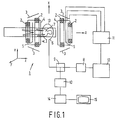
- a magnetic resonance apparatus 1 is diagrammatically shown.
- the apparatus comprises a set of main magnetic coils 2 for generating a stationary and homogeneous main magnetic field and several sets of gradient coils 3, 4 and 5 for superimposing additional magnetic fields with controllable strength and having a gradient in a selected direction.
- the direction of the main magnetic field is labelled the z direction, the two directions perpendicular thereto the x and y directions.
- the gradient coils are energised via a power supply 11.
- the apparatus further comprises radiation emitting means 6, an antenna or coil, for emitting radio-frequency pulses (RF-pulses) to an object or body 7, the radiation means being coupled to modulating means 8 for generating and modulating the RF-pulses.
- RF-pulses radio-frequency pulses
- a send-receive switch 9 is arranged to separate the received signals from the pulses to be emitted.
- the received NMR-signals are input to receiving and demodulating means 10.
- the emitting means 6 and 8 and the power supply 11 for the gradient coils 3, 4 and 5 are steered by a control system 12 to generate a predetermined sequence of RF-pulses and gradient field pulses.
- the demodulation means is coupled to a data processing unit 14, for example a computer, for transformation of the received signals into an image that can be made visible, for example on a visual display unit 15.
- the magnetic resonance apparatus 1 If the magnetic resonance apparatus 1 is put into operation with an object or body 7 placed in the magnetic field, a small excess of nuclear dipole moments (nuclear spins) in the body will be aligned in the direction of the magnetic field. In equilibrium, this causes a net magnetisation M 0 in the material of the body 7, directed in parallel with the magnetic field.
- the macroscopic magnetisation M 0 is manipulated by radiating to the body RF-pulses having a frequency equal to the Larmor frequency of the nuclei, thereby bringing the nuclear dipole moments in an excited state and re-orienting the magnetisation M 0 .
- the angle of rotation is called the flip-angle.
- Figure 2 shows a known sequence of RF-pulses and magnetic field gradients according to the so-called GRASE method.
- the figure shows four rows, labelled RF, indicating the occurrence of RF-pulses as a function of time, G x and G y , indicating the occurrence of magnetic gradient fields in the x - and y -directions, respectively, and MR, indicating the occurrence of the magnetic resonance signals in the body caused by the RF and gradient pulses.
- an excitation RF-pulse 21 is applied having a flip-angle ⁇ , followed at time t 1 by a first refocusing RF-pulse 22 having a flip-angle ⁇ .
- the values of ⁇ and ⁇ are usually chosen to be 90° and 180°, respectively. Sequences with flip-angles deviating from these values are, however, possible.
- a free induction decay (FID) nuclear magnetic resonance signal 51 is generated which vanishes rapidly when the individual precessing nuclear magnetic dipole moments loose phase coherence (dephase) due to local variations in the magnetic field.
- the refocusing RF-pulse 22 reverses the direction of these individual magnetic dipole moments without affecting the local magnetic field. Consequently, dephasing is reversed into a rephasing which, in the absence of magnetic field gradients, would result at a time t 2 , being equal to 2 ⁇ t 1 in an NMR spin-echo signal.
- a magnetic field 31 with a gradient in the x -direction is applied that also causes dephasing of the nuclear spins.
- a train 32 of read magnetic field gradients with alternating polarity is applied.
- each section of this train between reversals is termed a lobe of the read gradient.
- Each subsequent lobe causes the generation of a further echo signal, resulting in a series 52 of magnetic resonance echo signals.
- the sequence can be repeated a number of times by repetition of refocusing RF-pulses 23, 24, 25, ... with flip-angles ⁇ at times t 3 , t 4 , t 5 , ..., and subsequent trains 33, 34, 35, ..., of read gradient pulses with alternating polarity resulting in series of echo signals 53, 54, 55, ... .
- the time since a refocusing RF-pulse is indicated by a time parameter ⁇ which is zero at the moment of the spin-echo, i.e. the point in time to which the exciting RF-pulse is "mirrored" by the preceding refocusing RF-pulses.
- phase-encoding gradient field pulses are applied with the gradient in the y -direction, as indicated in the row G y . These gradients are applied in pairs 42-42', 43-43', 44-44', 45-45', ..., the second pulse in a pair removing the phase-encoding.
- additional blips 42", 43", 44", 45", ... in the G y -gradient are applied, modifying the phase encoding values of the echo signals.
- the measured samples of the magnetic resonance (echo) signals are distributed over the whole of k -space on parallel lines in the k x -direction.
- the positive and negative polarity read gradient pulses differ somewhat. These effects cause phase shifts ⁇ + and ⁇ - , for the positive and negative polarity read gradient pulses, respectively, which phase shifts manifest themselves during reconstruction of the MR image as if samples in k -space are shifted. For example, due to timing effects and eddy currents, such shifts can occur both in the k x and k y -directions.
- phase shifts ⁇ + ( x , y ) and ⁇ - ( x,y ), in particular the dependence in y, can be determined by means of a reference measurement comprising a spatial encoding in the y -direction.
- a reference measurement is illustrated in figure 4, for a sequence having an RF- and gradient pulse sequence with more than one refocusing RF-pulse.
- the illustrated sequence concerns a separate reference measurement. Apart from the phase encoding gradients, this reference sequence is identical to the sequence shown in figure 2.
- Excitation and refocusing RF-pulses 421, 422, 423, 424 and 425 with flip-angles ⁇ and ⁇ , respectively, are applied, as well as read gradients, 431, 432, 433, 434 and 435 and phase encoding gradient pairs 442-442', 443-443', 444-444', 445-445'.
- the phase encoding gradients have a time integrated strength that is substantially less than the time integrated strength of the corresponding phase encoding gradients in a normal measurement sequence as shown in figure 2.
- No magnetic field gradient blips are applied at the moments of reversal of the read gradient field G x .
- value in the normal measurements are acquired during the central portions of the read gradients, i.e. halfway in time between the refocusing RF-pulses, it is preferred to use that same portion of the reference measurement to obtain the phase shift values. This will minimise the effects of inhomogeneities in the stationary main magnetic field.
- the reference samples from the second set should be acquired with substantially the same time parameter ⁇ as the normal samples of the first set with the same (low) k y values.
- the early or late samples in the reference set are preferably to be used.
- the set of samples acquired with a positive polarity read gradient in this reference measurement has a similar spacing in k -space as the complete set of samples, i.e.
- blips can be applied at some of the reversals of the read gradient field to increase the number of lines acquired, while decreasing the number of times a single line is acquired, provided that each line is scanned with both polarities of the read-out gradient.
- Figure 5 shows a sequence of RF pulses and magnetic field gradients in which the measurements of the first and second sets of magnetic resonance signal samples are acquired following the same excitation RF-pulse.
- Figure 6 shows the corresponding trajectory in k -space.
- the sequence shown in figure 5 is largely identical to the sequence shown in figure 2.
- Excitation and refocusing RF pulses 521, 522, 523, 524 and 525 are alternated with a dephasing read gradient 531 and trains 532, 533, 534 and 535 of read gradient lobes with alternate polarity.
- Phase encoding gradient pairs 542-542', 543-543', 544-544' and 545-545' are applied as well as blips 542", 543", 544" and 545" for sampling on a trajectory covering a large area of k -space.
- no blip is applied at one reversal of the read gradient. Consequently, the line in k -space corresponding the accumulated value of the time-integrated strength of the phase encoding gradient is sampled twice, once with a positive and once with a negative polarity read gradient.
- the trajectories 662 and 664 in k -space each comprise one line scanned in positive and in negative k x -direction with the same k y -value. It can also be seen from figure 6 that some portion of k -space is not scanned, in the shown embodiment the lowest region. In practice this does not have a serious effect on the resulting image quality, the same information is available from another portions of k -space and the portions with high phase encoding values are of less importance anyway in the final reconstructed image.
- the sequence shown in figure 5 conforms to this recommendation.
- Field inhomogeneities may be, for example, due to the magnet, to susceptibility variations in the patient or to chemical shift.
- phase correction is substantially performed in the spatial domain.
- two two-dimensional Fourier transforms are performed on signal samples that belong to the first (operational) set, one Fourier transform using only the samples acquired with a positive polarity read gradient and one using only the samples acquired with a negative polarity read gradient. This is done by replacing the samples acquired with the opposite polarity gradient by zero during each of the transformations, i.e. multiplying the sampled data with "presence" functions W + ( k y ) and W - ( k y ), respectively, which are 1 for those k y values at which data are sampled with a positive and negative polarity read gradient, respectively, and are zero for other k y values.
- the results of these transforms will be called the "uncorrected positive partial image” and the “uncorrected negative partial image”.
- the phase patterns of the uncorrected positive and negative partial images are independently corrected with the respective phase errors ⁇ ⁇ ( x , y ), resulting in corrected positive and negative partial images.
- the phase corrected complex values from the partial images are to be combined by complex addition.
- the calculation of the modulus as usual in magnetic resonance imaging, completes the reconstruction.
- index "c” indicates the use of only data located in the sub-region of k -space that was sampled with both polarities of the read gradient (the central region).
- a tilde “ ⁇ ” indicates "phase corrected” and an asterix "*” complex conjugated. denotes a Fourier transform, the direction of a one-dimensional Fourier transform is indicated by an index.
- the correction starts with a one-dimensional Fourier transform of the measured signal samples, performed in the read ( x ) direction:
- a Fourier transform in the phase encoding ( y ) direction is performed using these functions, resulting in the uncorrected positive and partial images:
- the functions W + ( k y ) and W - ( k y ) are the previously discussed "presence" functions.
- a similar transform is performed for only the central region in k -space and for the "presence" functions W ⁇ : and
- the function f ( k y ) is a window function, preferably a Riesz- or Tukey-function, with which the samples from the central region may be multiplied. The use of such a window function reduces the effects of a sudden discontinuity at the edges of the central region.
- the uncorrected positive and negative partial images can now be corrected according to:
- the two partial images have to be added. This occurs in the ( x , k y ) domain as it is there that the polarity of the read gradient and the number of measurements for each k y value is known.
- the corrected partial images ( x , y ) first have to be transformed into that domain, as well as the corrected "presence" functions ( x , y ):
- the phase correction of the presence function is performed in the spatial domain according to
- the average linear phase increase ⁇ ⁇ ( x ) is estimated as:
- the normalisation performed, division by the square root of the product of the two absolute values, is not really essential. By doing so the weighted average phase increase is calculated.
- the optimally weighted combined data are then given by: and the complete phase corrected image is now obtained by Fourier transforming this data into the spatial domain:
- the usual further processing of MR images, such as calculation of the modulus is to be performed using the data from this complex image ( x , y ).
- phase errors are not due to errors caused by switching the phase encoding gradients G y .
- This assumption need not to be valid, for example, due to eddy currents the actual value of the gradient magnetic field may vary during a sequence as a function of the switching history of G y .
- the effects of this difference can be reduced by introduction of two blips, each with a reduced time-integrated strength.
- the measurements of the same line in k -space measured with a positive and a negative polarity read gradient are then measured during different echoes or even are preceded by different excitation RF-pulses.
- phase errors do not significantly depend from the rank number of the excitation RF pulse nor from T 2 , this does not introduce any further errors. Additionally, in this procedure the number of lines devoted to acquisition of the first set of signal samples is less affected.
- this further phase difference its dependence on the time parameter ⁇ has to be determined.
- two blips of the phase encoding gradient are to be absent in a measurement sequence, i.e. the sequence shown in figure 5 with also the second blip in G y absent.
- the phase error is to be determined from the central lobe and for the other polarity from the two adjacent lobes.
- Correction of the data can be performed according to procedure described with the following formulas.
- An index "+” or “-” indicates partial images from measurements with positive or negative read polarity gradient pulses, respectively.
- tilde “ ⁇ " and asterix “*” are used for phase corrected and complex conjugated data, respectively.
- the magnetic field inhomogeneities are minor, the phases ⁇ e and ⁇ l can be determined unambiguously.
- the corrected images are obtained by the following calculations: These partial images are to be combined by the weighted addition as described hereinbefore.
- An additional advantage of the use of three central lobes for correction is the improved symmetry. Because of this symmetry, artefacts, due to T 2 decay are present only in the imaginary part of the final phase corrected image, and can be avoided easily by use of the real part, rather than the modulus of the data representing the image.
- an estimate can be made of the phase errors and the data can be corrected using the procedure according to the present invention.
- the samples in the unmeasured region of k -space can be estimated, for example as indicated in EP-A 0 250 050.
- FIG. 7a shows the trajectory in k -space for a normal measurement.
- Figure 7b shows the trajectory for a reference measurement, in which the distance in the phase encoding direction k y between the scan lines is halved as compared to the normal measurement. This is achieved by applying the phase encoding gradients G y in the reference sequence with a time-integrated strength that is half the time-integrated strength of the corresponding gradient in the normal sequence.
- a single reference measurement can, of course, be used to correct a plurality of repeated images, for example for studying time dependent phenomenons such as the inflow or outwash of a contrast medium, or activities in the brain.
Landscapes
- Physics & Mathematics (AREA)
- Health & Medical Sciences (AREA)
- General Health & Medical Sciences (AREA)
- Nuclear Medicine, Radiotherapy & Molecular Imaging (AREA)
- Radiology & Medical Imaging (AREA)
- Engineering & Computer Science (AREA)
- Signal Processing (AREA)
- High Energy & Nuclear Physics (AREA)
- Condensed Matter Physics & Semiconductors (AREA)
- General Physics & Mathematics (AREA)
- Magnetic Resonance Imaging Apparatus (AREA)
Claims (8)
- Procédé pour l'imagerie par résonance magnétique d'un corps placé dans un champ magnétique principal stationnaire et sensiblement homogène, le procédé comprenantcaractérisé en ce quel'application d'une impulsion de radiofréquence d'excitation pour l'excitation de moments dipolaires nucléaires dans au moins une partie du corps, suivie parla commutation d'une pluralité d'impulsions de gradient de lecture de champ magnétique ayant une polarité positive et une polarité négative qui alternent pour engendrer une pluralité de signaux de résonance magnétique dans la partie excitée et simultanément la mesure d'un premier jeu d'échantillons de signaux desdits signaux de résonance magnétique,de façon que lesdits échantillons de signaux provenant dudit premier jeu soient situés sur des lignes allant en va-et-vient dans l'espace k, les lignes ayant une distance mutuelle dans une direction perpendiculaire à la direction des lignes,la mesure d'un deuxième jeu d'échantillons de signaux des deux polarités du gradient de lecture et la détermination, à partir dudit deuxième jeu, d'un jeu d'erreur de phase pour la correction des erreur de phase dans ledit premier jeu, etla formation par transformation et correction des erreurs de phase, d'une image à partir des premiers jeux d'échantillons de signaux,les échantillons de signaux du deuxième jeu sont situés sur des lignes qui couvrent au moins une sous-région bidimensionnelle dans l'espace k, dans lequel deuxième jeu les mêmes lignes que dans ledit premier jeu ou des lignes étroitement adjacentes dans l'espace k aux lignes dans ledit premier jeu, sont mesurées chacune avec les deux polarités du gradient de lecture,de sorte que les échantillons de signaux mesurés dans ladite sous-région avec une polarité donnée du gradient de lecture de champ magnétique sont situés sur des lignes qui sont espacées l'une de l'autre d'une distance qui est égale ou inférieure à ladite distance mutuelle dans le premier jeu.
- Procédé suivant la revendication 1, caractérisé en ce que la sous-région de l'espace k comprend une bande qui s'étend dans la direction des lignes et dans laquelle l'origine de l'espace k est située.
- Procédé suivant la revendication 1 ou 2, caractérisé en ce que la ou les impulsions de radiofréquence d'excitation après lesquelles ledit deuxième jeu d'échantillons de signaux est mesuré, sont distinctes de la ou les impulsions de radiofréquence d'excitation appliquées pour la mesure dudit premier jeu d'échantillons de signaux.
- Procédé suivant la revendication 1 ou 2, caractérisé en ce que les échantillons de signaux dans ledit deuxième jeu d'échantillons de signaux sont mesurés après la même impulsion de radiofréquence d'excitation que les échantillons de signaux dudit premier jeu.
- Procédé suivant la revendication 4, caractérisé en ce que des mesures dans le deuxième jeu sont intégrées à l'intérieur d'une séquence de mesure du premier jeu en n'appliquant pas les gradients de codage de phase à un moment d'inversion de polarité des impulsions de gradients de lecture ou en appliquant des gradients de codage de phase réduits par comparaison avec les gradients de codage de phase appliqués pour la mesure du premier jeu à un tel moment.
- Procédé suivant l'une quelconque des revendications précédentes caractérisé en ce qu'une ou plusieurs impulsions de radiofréquence de refocalisation sont appliquées après l'impulsion de radiofréquence d'excitation et en ce que les gradients de lecture de champs magnétiques sont appliqués et les échantillons de signaux sont mesurés après la ou les impulsions de refocalisation de radiofréquence respectives.
- Procédé suivant l'une quelconque des revendications précédentes caractérisé en ce que signaux de résonance magnétique du premier jeu sont acquis à partir d'une moitié de l'espace k.
- Appareil pour l'imagerie par résonance magnétique d'un corps (7) placé dans un champ magnétique principal stationnaire et sensiblement homogène suivant un procédé suivant l'une quelconque des revendications précédentes, l'appareil comprenant des moyens pour établir le champ magnétique principal (2), des moyens pour engendrer des champs magnétiques de gradients (3, 4, 5) superposés au champ magnétique principal, des moyens (6, 8) pour émettre des impulsions de radiofréquence vers le corps (7), des moyens de commande (12) pour piloter la génération des champs magnétiques de gradients et des impulsions de radiofréquence, des moyens pour recevoir (6, 10) et échantillonner des signaux de résonance magnétique engendrés par les séquences d'impulsions de radiofréquence et les champs magnétiques de gradients commutés et des moyens de reconstruction pour former une image à partir de ces échantillons de signaux par transformation et correction de phase, lesquels moyens de commande (12) étant conçus pourcaractérisé en ce que les moyens de commande (12) sont en outre agencés pourappliquer une impulsion de radiofréquence d'excitation pour l'excitation des moments dipolaires dans au moins une partie du corps, suivie parla commutation d'une pluralité de gradients de lecture de champs magnétiques ayant une polarité positive et une polarité négative en alternance pour engendrer une pluralité de signaux magnétiques de résonance dans la partie excitée et simultanément mesurer un premier jeu d'échantillons de signaux des signaux de résonance magnétique,de façon à ce que les échantillons de signaux provenant dudit premier jeu soient situés sur des lignes allant en va-et-vient dans l'espace k, les lignes ayant une distance mutuelle dans une direction perpendiculaire à leur direction, etla mesure d'un deuxième jeu d'échantillons de signaux des deux polarités du gradient de lecture et la détermination à partir dudit deuxième jeu, d'un jeu d'erreurs de phase pour la détermination d'un jeu d'erreurs de phase, à partir dudit deuxième jeu utilisé pour la correction des erreurs de phase dans ledit premier jeu,mesurer les échantillons de signaux du deuxième jeu de lignes qui couvrent au moins une sous-région bidimensionnelle de l'espace k, les mêmes lignes que dans le premier jeu ou des lignes étroitement adjacentes dans l'espace k aux lignes dudit premier jeu étant chacune mesurée avec les deux polarités du gradient de lecture,de sorte que les échantillons de signaux mesurés dans ladite sous-région avec une polarité donnée du gradient de lecture de champ magnétique sont situés sur des lignes qui sont espacées l'une de l'autre d'une distance égale ou inférieure à la distance mutuelle dans le premier jeu.
Applications Claiming Priority (2)
| Application Number | Priority Date | Filing Date | Title |
|---|---|---|---|
| EP93202678 | 1993-09-16 | ||
| EP93202678 | 1993-09-16 |
Publications (2)
| Publication Number | Publication Date |
|---|---|
| EP0644437A1 EP0644437A1 (fr) | 1995-03-22 |
| EP0644437B1 true EP0644437B1 (fr) | 1999-05-12 |
Family
ID=8214093
Family Applications (1)
| Application Number | Title | Priority Date | Filing Date |
|---|---|---|---|
| EP94202628A Expired - Lifetime EP0644437B1 (fr) | 1993-09-16 | 1994-09-13 | Correction de la polarité du gradient de lecture dans l'IRM par EPI et GRASE |
Country Status (4)
| Country | Link |
|---|---|
| US (1) | US5647362A (fr) |
| EP (1) | EP0644437B1 (fr) |
| JP (1) | JP3529446B2 (fr) |
| DE (1) | DE69418404T2 (fr) |
Families Citing this family (32)
| Publication number | Priority date | Publication date | Assignee | Title |
|---|---|---|---|---|
| EP0644437B1 (fr) | 1993-09-16 | 1999-05-12 | Koninklijke Philips Electronics N.V. | Correction de la polarité du gradient de lecture dans l'IRM par EPI et GRASE |
| JPH07323021A (ja) * | 1994-05-31 | 1995-12-12 | Shimadzu Corp | Mrイメージング装置 |
| DE4438488A1 (de) * | 1994-10-28 | 1996-05-02 | Philips Patentverwaltung | MR-Verfahren und Anordnung zur Durchführung desselben |
| JP3496898B2 (ja) * | 1995-03-03 | 2004-02-16 | 株式会社日立メディコ | 核磁気共鳴撮影装置 |
| US5957843A (en) * | 1995-08-14 | 1999-09-28 | Board Of Trustees Of The Leland Stanford Junior University | Partial flyback echo-planar imaging |
| DE19606090C2 (de) * | 1996-02-19 | 1998-01-22 | Siemens Ag | Verfahren zur funktionellen Bildgebung mittels magnetischer Resonanz |
| JPH09234188A (ja) * | 1996-02-29 | 1997-09-09 | Shimadzu Corp | Mrイメージング装置 |
| JP3544782B2 (ja) * | 1996-04-16 | 2004-07-21 | 株式会社東芝 | 磁気共鳴診断装置 |
| US6172502B1 (en) * | 1996-07-08 | 2001-01-09 | U.S. Philips Corporation | Method of and device for imaging by means of magnetic resonance |
| KR19980031952A (ko) * | 1996-10-31 | 1998-07-25 | 김광호 | 비월주사 에코 플래너 자기공명 영상법 |
| US5864233A (en) * | 1997-02-22 | 1999-01-26 | General Electric Company | Method to reduce eddy current effects in diffusion-weighted echo planar imaging |
| US5923168A (en) * | 1997-06-17 | 1999-07-13 | General Electric Company | Correction of artifacts caused by Maxwell terms in slice offset echo planar imaging |
| US5917323A (en) * | 1997-07-01 | 1999-06-29 | General Electric Company | Correction of axial image signal fall off caused by Maxwell terms |
| GB9726143D0 (en) | 1997-12-10 | 1998-02-11 | Chapman Barry L | Ghost artifact reduction |
| US6249595B1 (en) * | 1998-01-22 | 2001-06-19 | General Electric Company | Iterative reconstruction for EPI |
| US6285187B1 (en) | 1999-04-28 | 2001-09-04 | General Electric Company | Method and apparatus for reducing artifacts in echo planar imaging |
| US6259250B1 (en) | 1999-04-28 | 2001-07-10 | General Electric Company | Method and apparatus for reducing artifacts in echo planar imaging |
| US6448773B1 (en) | 2000-02-24 | 2002-09-10 | Toshiba America Mri, Inc. | Method and system for measuring and compensating for eddy currents induced during NMR imaging operations |
| DE10112880A1 (de) * | 2001-03-15 | 2002-10-02 | Forschungszentrum Juelich Gmbh | Verfahren zur Untersuchung einer Probe mittels Erzeugung einer Bildgebungssequenz |
| DE10112879A1 (de) * | 2001-03-15 | 2002-10-02 | Forschungszentrum Juelich Gmbh | Verfahren zur Untersuchung einer Probe mittels Erzeugung und Ermittlung von Echosignalen |
| JP3878429B2 (ja) * | 2001-04-05 | 2007-02-07 | ジーイー・メディカル・システムズ・グローバル・テクノロジー・カンパニー・エルエルシー | Mri装置 |
| US6487436B1 (en) * | 2001-04-17 | 2002-11-26 | Ge Medical Systems Global Technology Company, Llc | Switchable field of view apparatus and method for magnetic resonance imaging |
| JP4122452B2 (ja) * | 2001-10-15 | 2008-07-23 | 株式会社日立メディコ | 磁気共鳴撮像装置 |
| US6630829B1 (en) | 2002-04-22 | 2003-10-07 | Ge Medical Systems Global Technology Co., Llc | Gradient coil set capable of producing a variable field of view |
| US8072215B2 (en) | 2006-07-06 | 2011-12-06 | Koninklijke Philips Electronics N.V. | Magnetic resonance device and method |
| KR100852402B1 (ko) * | 2006-12-21 | 2008-08-14 | 한국과학기술원 | 비선형 위상 보정 방법. |
| JP5611882B2 (ja) * | 2010-05-31 | 2014-10-22 | 株式会社東芝 | 磁気共鳴イメージング装置 |
| JP5925529B2 (ja) * | 2011-03-31 | 2016-05-25 | 株式会社東芝 | 磁気共鳴イメージング装置 |
| US8981776B2 (en) * | 2011-04-22 | 2015-03-17 | The General Hospital Corporation | Method for magnetic resonance imaging with controlled aliasing |
| KR101442619B1 (ko) * | 2012-11-26 | 2014-09-22 | 삼성전자주식회사 | Mri 시스템 및 mri 시스템 진단 방법 |
| EP3715896B1 (fr) * | 2019-03-27 | 2023-02-15 | Siemens Healthcare GmbH | Minimisation de pertes de signal en imagerie multi-écho |
| CN113534031B (zh) * | 2020-04-21 | 2023-05-05 | 上海联影医疗科技股份有限公司 | 图像域数据生成方法、计算机设备和可读存储介质 |
Family Cites Families (11)
| Publication number | Priority date | Publication date | Assignee | Title |
|---|---|---|---|---|
| US4851779A (en) * | 1987-08-14 | 1989-07-25 | Picker International, Inc. | Three dimensional volume imaging with conjugate symmetrization |
| JP2644831B2 (ja) * | 1988-07-06 | 1997-08-25 | 株式会社日立製作所 | Nmrイメージングにおける画像再構成方法 |
| JPH02215440A (ja) * | 1989-02-17 | 1990-08-28 | Toshiba Corp | 磁気共鳴映像装置 |
| DE4024164A1 (de) * | 1989-08-11 | 1991-02-14 | Siemens Ag | Verfahren zur verbesserung des signal-rausch-verhaeltnisses bei einem kernspin-tomographiegeraet |
| DE4005675C2 (de) * | 1990-02-22 | 1995-06-29 | Siemens Ag | Verfahren zur Unterdrückung von Artefakten bei der Bilderzeugung mittels kernmagnetischer Resonanz |
| US5151656A (en) * | 1990-12-11 | 1992-09-29 | General Electric Company | Correction of nmr data acquired by an echo-planar technique |
| US5270654A (en) * | 1991-07-05 | 1993-12-14 | Feinberg David A | Ultra-fast multi-section MRI using gradient and spin echo (grase) imaging |
| JP3153574B2 (ja) * | 1991-08-23 | 2001-04-09 | 株式会社東芝 | 磁気共鳴映像装置 |
| JPH0556944A (ja) * | 1991-08-29 | 1993-03-09 | Toshiba Corp | 磁気共鳴イメージング装置 |
| DE4139509C2 (de) * | 1991-11-29 | 1995-09-07 | Siemens Ag | Bildgebendes Verfahren für ein Kernspintomographiegerät, das eine Pulssequenz nach dem Echoplanarverfahren verwendet |
| EP0644437B1 (fr) | 1993-09-16 | 1999-05-12 | Koninklijke Philips Electronics N.V. | Correction de la polarité du gradient de lecture dans l'IRM par EPI et GRASE |
-
1994
- 1994-09-13 EP EP94202628A patent/EP0644437B1/fr not_active Expired - Lifetime
- 1994-09-13 DE DE69418404T patent/DE69418404T2/de not_active Expired - Fee Related
- 1994-09-14 US US08/306,095 patent/US5647362A/en not_active Expired - Fee Related
- 1994-09-14 JP JP22046294A patent/JP3529446B2/ja not_active Expired - Fee Related
Also Published As
| Publication number | Publication date |
|---|---|
| DE69418404D1 (de) | 1999-06-17 |
| US5647362A (en) | 1997-07-15 |
| EP0644437A1 (fr) | 1995-03-22 |
| DE69418404T2 (de) | 1999-11-11 |
| JPH07171122A (ja) | 1995-07-11 |
| JP3529446B2 (ja) | 2004-05-24 |
Similar Documents
| Publication | Publication Date | Title |
|---|---|---|
| EP0644437B1 (fr) | Correction de la polarité du gradient de lecture dans l'IRM par EPI et GRASE | |
| US5402067A (en) | Apparatus and method for rare echo imaging using k-space spiral coverage | |
| EP2414861B1 (fr) | Imagerie par résonance magnétique présentant un contraste d'imagerie amélioré | |
| US5786692A (en) | Line scan diffusion imaging | |
| US5450010A (en) | Magnetic resonance imaging method and apparatus employing eddy current compensation by modification of gradient size | |
| US4970457A (en) | MRI compensated for spurious rapid variations in static magnetic field during a single MRI sequence | |
| US5561370A (en) | Artefact suppression in GRASE Mr imaging | |
| EP1391746B1 (fr) | Imagerie à résonance magnétique parallele utilisant des signaux d'écho navigateurs | |
| US5942897A (en) | Magnetic resonance imaging apparatus | |
| US5570019A (en) | Method for magnetic resonance spectroscopic imaging with multiple spin-echoes | |
| EP0529527B1 (fr) | Procédé et appareil d'imagerie rapide par résonance magnétique à qualité d'image améliorée | |
| US6472872B1 (en) | Real-time shimming of polarizing field in magnetic resonance system | |
| GB2320576A (en) | A multi-echo Dixon water and fat separation sequence | |
| JP3970371B2 (ja) | Mriシーケンス | |
| US5602476A (en) | Ultra-fast MR imaging data acquisition scheme using mixed bandwidth data | |
| US5459400A (en) | Method to enhance the sensitivity of MRI for magnetic susceptibility effects | |
| US20110210733A1 (en) | B1-robust and t1-robust species suppression in mri | |
| US6265872B1 (en) | Diffusion detection by means of magnetic resonance | |
| EP0835454B1 (fr) | Imagerie écho-planaire avec décalage temporaire de l'écho et compensation du mouvement | |
| US5581181A (en) | Grase MRI with read gradient polarity correction and T2 measurement | |
| US7180290B2 (en) | Method for k-space data acquisition and MRI device | |
| US5337000A (en) | Method for fast imaging in nuclear magnetic resonance tomography | |
| US5410249A (en) | Method and apparatus for magnetic resonance imaging | |
| Oshio et al. | Single‐shot GRASE imaging without fast gradients | |
| US5402787A (en) | Method and apparatus for magnetic resonance imaging |
Legal Events
| Date | Code | Title | Description |
|---|---|---|---|
| PUAI | Public reference made under article 153(3) epc to a published international application that has entered the european phase |
Free format text: ORIGINAL CODE: 0009012 |
|
| AK | Designated contracting states |
Kind code of ref document: A1 Designated state(s): DE FR GB NL |
|
| 17P | Request for examination filed |
Effective date: 19950922 |
|
| 17Q | First examination report despatched |
Effective date: 19970627 |
|
| GRAG | Despatch of communication of intention to grant |
Free format text: ORIGINAL CODE: EPIDOS AGRA |
|
| GRAG | Despatch of communication of intention to grant |
Free format text: ORIGINAL CODE: EPIDOS AGRA |
|
| GRAH | Despatch of communication of intention to grant a patent |
Free format text: ORIGINAL CODE: EPIDOS IGRA |
|
| GRAH | Despatch of communication of intention to grant a patent |
Free format text: ORIGINAL CODE: EPIDOS IGRA |
|
| GRAA | (expected) grant |
Free format text: ORIGINAL CODE: 0009210 |
|
| AK | Designated contracting states |
Kind code of ref document: B1 Designated state(s): DE FR GB NL |
|
| PG25 | Lapsed in a contracting state [announced via postgrant information from national office to epo] |
Ref country code: NL Free format text: LAPSE BECAUSE OF FAILURE TO SUBMIT A TRANSLATION OF THE DESCRIPTION OR TO PAY THE FEE WITHIN THE PRESCRIBED TIME-LIMIT Effective date: 19990512 |
|
| REF | Corresponds to: |
Ref document number: 69418404 Country of ref document: DE Date of ref document: 19990617 |
|
| ET | Fr: translation filed | ||
| PG25 | Lapsed in a contracting state [announced via postgrant information from national office to epo] |
Ref country code: GB Free format text: LAPSE BECAUSE OF NON-PAYMENT OF DUE FEES Effective date: 19990913 |
|
| PLBE | No opposition filed within time limit |
Free format text: ORIGINAL CODE: 0009261 |
|
| STAA | Information on the status of an ep patent application or granted ep patent |
Free format text: STATUS: NO OPPOSITION FILED WITHIN TIME LIMIT |
|
| 26N | No opposition filed | ||
| GBPC | Gb: european patent ceased through non-payment of renewal fee |
Effective date: 19990913 |
|
| REG | Reference to a national code |
Ref country code: FR Ref legal event code: D6 |
|
| PGFP | Annual fee paid to national office [announced via postgrant information from national office to epo] |
Ref country code: FR Payment date: 20050928 Year of fee payment: 12 |
|
| PGFP | Annual fee paid to national office [announced via postgrant information from national office to epo] |
Ref country code: DE Payment date: 20051117 Year of fee payment: 12 |
|
| PG25 | Lapsed in a contracting state [announced via postgrant information from national office to epo] |
Ref country code: DE Free format text: LAPSE BECAUSE OF NON-PAYMENT OF DUE FEES Effective date: 20070403 |
|
| REG | Reference to a national code |
Ref country code: FR Ref legal event code: ST Effective date: 20070531 |
|
| PG25 | Lapsed in a contracting state [announced via postgrant information from national office to epo] |
Ref country code: FR Free format text: LAPSE BECAUSE OF NON-PAYMENT OF DUE FEES Effective date: 20061002 |