EP0644162B1 - Verfahren zur Steuerung der freien Verformung von thermoplastischem Material - Google Patents
Verfahren zur Steuerung der freien Verformung von thermoplastischem Material Download PDFInfo
- Publication number
- EP0644162B1 EP0644162B1 EP94110317A EP94110317A EP0644162B1 EP 0644162 B1 EP0644162 B1 EP 0644162B1 EP 94110317 A EP94110317 A EP 94110317A EP 94110317 A EP94110317 A EP 94110317A EP 0644162 B1 EP0644162 B1 EP 0644162B1
- Authority
- EP
- European Patent Office
- Prior art keywords
- deformation
- constriction
- diameter
- takes place
- measured
- Prior art date
- Legal status (The legal status is an assumption and is not a legal conclusion. Google has not performed a legal analysis and makes no representation as to the accuracy of the status listed.)
- Expired - Lifetime
Links
- 238000000034 method Methods 0.000 title claims description 55
- 239000012815 thermoplastic material Substances 0.000 title claims description 4
- 239000011521 glass Substances 0.000 claims description 27
- 238000012545 processing Methods 0.000 claims description 15
- 238000005259 measurement Methods 0.000 claims description 14
- 238000004519 manufacturing process Methods 0.000 claims description 13
- 230000005855 radiation Effects 0.000 claims description 13
- 238000010438 heat treatment Methods 0.000 claims description 12
- 230000008569 process Effects 0.000 claims description 9
- 239000007858 starting material Substances 0.000 claims description 6
- 239000007789 gas Substances 0.000 claims description 5
- 239000000463 material Substances 0.000 claims description 5
- 230000003595 spectral effect Effects 0.000 claims description 5
- 230000008859 change Effects 0.000 claims description 4
- 230000000694 effects Effects 0.000 claims description 4
- QVGXLLKOCUKJST-UHFFFAOYSA-N atomic oxygen Chemical compound [O] QVGXLLKOCUKJST-UHFFFAOYSA-N 0.000 claims description 3
- 238000002485 combustion reaction Methods 0.000 claims description 3
- 239000001301 oxygen Substances 0.000 claims description 3
- 229910052760 oxygen Inorganic materials 0.000 claims description 3
- 238000001816 cooling Methods 0.000 claims description 2
- 238000009826 distribution Methods 0.000 claims description 2
- 230000005670 electromagnetic radiation Effects 0.000 claims description 2
- 238000011065 in-situ storage Methods 0.000 claims description 2
- 230000003287 optical effect Effects 0.000 claims description 2
- 230000000750 progressive effect Effects 0.000 claims description 2
- 230000001419 dependent effect Effects 0.000 claims 1
- 239000003708 ampul Substances 0.000 description 19
- 238000012937 correction Methods 0.000 description 14
- 230000015572 biosynthetic process Effects 0.000 description 5
- 230000008901 benefit Effects 0.000 description 4
- 230000001276 controlling effect Effects 0.000 description 4
- 230000001105 regulatory effect Effects 0.000 description 4
- 238000012549 training Methods 0.000 description 4
- 230000009471 action Effects 0.000 description 3
- 238000007493 shaping process Methods 0.000 description 3
- 239000000047 product Substances 0.000 description 2
- 230000002123 temporal effect Effects 0.000 description 2
- 238000012360 testing method Methods 0.000 description 2
- 241001156002 Anthonomus pomorum Species 0.000 description 1
- 208000027418 Wounds and injury Diseases 0.000 description 1
- 238000007630 basic procedure Methods 0.000 description 1
- 230000006835 compression Effects 0.000 description 1
- 238000007906 compression Methods 0.000 description 1
- 230000001143 conditioned effect Effects 0.000 description 1
- 238000010924 continuous production Methods 0.000 description 1
- 230000006378 damage Effects 0.000 description 1
- 238000013461 design Methods 0.000 description 1
- 238000011161 development Methods 0.000 description 1
- 238000010586 diagram Methods 0.000 description 1
- 238000004033 diameter control Methods 0.000 description 1
- 230000035622 drinking Effects 0.000 description 1
- 238000011156 evaluation Methods 0.000 description 1
- 238000002474 experimental method Methods 0.000 description 1
- 230000002349 favourable effect Effects 0.000 description 1
- 239000012467 final product Substances 0.000 description 1
- 230000014509 gene expression Effects 0.000 description 1
- 230000006872 improvement Effects 0.000 description 1
- 208000014674 injury Diseases 0.000 description 1
- 238000012821 model calculation Methods 0.000 description 1
- GGYFMLJDMAMTAB-UHFFFAOYSA-N selanylidenelead Chemical compound [Pb]=[Se] GGYFMLJDMAMTAB-UHFFFAOYSA-N 0.000 description 1
- 239000007787 solid Substances 0.000 description 1
Images

Classifications
-
- C—CHEMISTRY; METALLURGY
- C03—GLASS; MINERAL OR SLAG WOOL
- C03B—MANUFACTURE, SHAPING, OR SUPPLEMENTARY PROCESSES
- C03B23/00—Re-forming shaped glass
- C03B23/04—Re-forming tubes or rods
- C03B23/11—Reshaping by drawing without blowing, in combination with separating, e.g. for making ampoules
- C03B23/112—Apparatus for conveying the tubes or rods in a curved path around a vertical axis through one or more forming stations
-
- Y—GENERAL TAGGING OF NEW TECHNOLOGICAL DEVELOPMENTS; GENERAL TAGGING OF CROSS-SECTIONAL TECHNOLOGIES SPANNING OVER SEVERAL SECTIONS OF THE IPC; TECHNICAL SUBJECTS COVERED BY FORMER USPC CROSS-REFERENCE ART COLLECTIONS [XRACs] AND DIGESTS
- Y10—TECHNICAL SUBJECTS COVERED BY FORMER USPC
- Y10S—TECHNICAL SUBJECTS COVERED BY FORMER USPC CROSS-REFERENCE ART COLLECTIONS [XRACs] AND DIGESTS
- Y10S65/00—Glass manufacturing
- Y10S65/13—Computer control
Definitions
- the invention relates to a method for controlling the free deformation of thermoplastic material in an automated process for further processing of the material to articles, especially in the manufacture of ampoules, vials and the like made of glass tube, in which to achieve a high dimensional accuracy of the articles depending on one Target / actual comparison of those achieved in a given processing step
- Deformation of a workpiece in the deformation area a correction intervention about the influence of heat on the starting material in the Heating phase takes place, the size of the deformation of influencing variables, such as B. the exposure time of the burner, the calorific value of the gas, the temporal Constancy of the quantities of gas, oxygen and combustion air, the Temperature, drafts, progressive consumption and geometric Dimensions of the glass tube depends.
- MM 30 a 30 station vertical machine from Modern Mecanique, F-77507 Chelles Cedex. Details of this machine are, for example contained in company documents.
- the processing step follows.
- the Deformation occurs by constriction, pulling or compression, by the action of flame or by lowering or lifting the lower chuck.
- the processing machine consists of 30 such clamping stations distributed about the scope of the carousel. Heating of the area to be processed the tube is made via a number of stationary burners which are pivotally mounted are and over a maximum possible distance of the carousel rotation can follow and act on the glass tube. There will be one ampoule per Clamping station and carousel rotation generated.
- Free Deformation i. H. Deformation without shaping solid.
- the size of the deformation only depends on the influencing factors mentioned at the beginning. These are subject temporal fluctuations and therefore cause fluctuations in the free Shaping.
- the ampoule skewer To quickly and safely fill the ampoules in the aforementioned To ensure high-performance machines in the pharmaceutical industry are on the ampoule skewer in terms of its dimensional accuracy high demands made. Especially with diameter and centricity of the ampoule skewer are very tight tolerances. For example it should be noted that the spit diameter of a 5 ml ampoule according to the above described methods can fluctuate by up to ⁇ 0.5 mm. From the processors However, companies will adhere to the tolerances of maximum ⁇ 0.2 mm required.
- the skewer diameter is determined according to Techner by mechanical scanning using two disks, the diameter are large enough to avoid injury to the ampoule skewer.
- the Measurement provides a single diameter measurement per skewer.
- the heating of the spit area is determined according to the Techner Diameter deviation over the mid-term of two individually controlled Burner, which in the preheating zone on the spit area of the Act on the workpiece, controlled.
- the relationship between diameter deviation and the lead time is determined empirically by tests according to Techner.
- the resultant may result Control only on the following workpiece impact.
- the long dead time causes short-term occurrences Faults during the heating phase, such as. B.
- the influencing factors mentioned at the beginning free deformation such as drafts, short-term changes in the amount of gas, oxygen and combustion air, temperature jumps in the environment, etc., cannot be detected by the controller.
- the object of the invention is a method of the type mentioned develop that the dead time is as short as possible and also in the short term Any faults occurring in the heating phase are compensated for by the control can be.
- the method according to the invention uses the measurement of the deformation to one Time at which all influencing factors had a measurable impact and still did there is a sufficiently large remaining deformation.
- the measurement results allow control of the remaining deformation.
- the correction intervention can therefore take into account all influences except for the error from the error respectively.
- the method thus has the advantage that there is an individual intervention enables the deformation process of each individual workpiece.
- the invention will be used without restriction for generality their great importance for this process using the example of spit production during ampoule production on the MM30 mentioned at the beginning using the Figures and an embodiment explained.
- the invention is intended however, in no way limited to ampoule production will.
- the invention as such can be like the following described preferred procedures easily to any Process for processing thermoplastic material applied become, without the skilled person has to be inventive for this.
- the the basic procedure is the same for all processes and can be following description of the application of the method to the Ampoule production can be removed. Some examples of others Possible uses are given below.
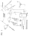
- Figure 1 shows a schematic representation of an arrangement for Implementation of the method according to the invention in ampoule production, Particularly suitable for controlling the skewer formation on an MM30 is.
- Device parts of the MM30, which are used in the implementation of the invention Procedures do not play a role for the sake of clarity not shown in the figure.
- the figure shows glass tubes (2) clamped in chucks (1), those on one indicated by the "quarter circle” arrangement of the burners Carousel are arranged. Heating of the areas to be processed the pipes, in this example the spit areas, are in the preheating zone over a number of stationary burners (3) (usually 14), which are pivoted and over a maximum possible distance of the Carousel rotation can follow and act on the glass tube (2).
- IR cameras are known per se and are therefore not used here further described.
- the IR camera (4) is used to measure up to this Station already deformed due to the preheating Spit area. As a rule, up to this point, about 80% of the Spike heating has already occurred, so that the remaining ones for the correction intervention 20% are still available.
- the deformation that has already occurred is measured in the case of the invention
- the method is preferably contactless, for example by means of optical dimension sensors.
- the one from the heated one is advantageously used Starting material emitted heat radiation used, it is still has proven to be particularly favorable, the one emitted by the workpiece Measure radiation in a spectral range in which that from the burner flames emitted radiation does not interfere. This is simple possible by inserting a suitable filter. Will about it In addition, the heat radiation is still measured in a spectral range in which the radiation intensity is independent of the material thickness an evenly illuminated one with the help of the IR camera mentioned above Image of the deformation area with sharp contours. The determination of dimensions This makes the workpiece in the deformation area essential facilitated. A more precise measurement is also possible.
- the IR camera (4) has which usually takes 50 measurements / second, an extended field of view.
- This "multiple measurement” allows in a simple manner the assessment of the ovality and eccentricity of the workpieces (2) in the Deformation area. Impermissibly oval or eccentric skewers can via the controller (5) shown in the figure as a block in a Good / bad sorting must be eliminated.
- a clock is designated in the figure.
- the clock (6) transmits the period from tube to tube and thus the maximum possible Burner runtime.
- the reset time is smaller than that Period duration.
- the controller (5) essentially contains the one determined by experiment Characteristic curve for the relationship between the deviation of the actual and target diameters the constriction and the resulting change in Control quantity.
- the empirical determination of this characteristic has possible model calculations have the advantage that they usually give more accurate results delivers because, for example, all machine influences are automatic are included.
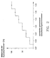
- Figure 2 shows a possible characteristic curve. A description this characteristic follows below.
- the correction intervention takes place over the idle time of two individually controlled burners (7). Corrective intervention is also possible by sequentially switching a series of torches on or off or by adding O 2 to the individually controllable torches, which does not result in a change in the flame temperature, but rather a shift in the hot zone of the flame towards the workpiece becomes. Furthermore, the correction intervention can also be carried out by controlled cooling.
- a space-saving and elegant method is the correction intervention via the intensity, intensity distribution and / or duration of exposure to electromagnetic radiation, in particular laser radiation, since measurement and intervention can take place in one station.
- electromagnetic radiation in particular laser radiation
- CO 2 laser is advisable, since this is a technically mature development, and CO 2 lasers are also inexpensive and highly efficient.
- Figure 2 shows a characteristic curve for the correction intervention over the two individually controllable burner is suitable. It is advantageous here the traveling time of the correction torches in integer multiples of the rotation period of the tube to prevent the formation of oval skewers. The travel time of the correction torch is above the normalized measured constriction diameter.
- the characteristic was obtained by setting both correction interventions to 50% and the burners of the preheating section and the individually controllable burners were set so that the average skewer diameter produced the desired target skewer diameter correspond (conventional known setting the machine). It was then checked whether the individually controllable burner the resulting skewer diameter 0.4 mm below the nominal diameter and with minimal intervention 0.4 mm above the Target diameter are generated. In the event of a discrepancy, iterative Prefire and correction fire improved.
- the determination of the rate of change of the constriction diameter can be useful in cases where this is particularly high.
- the O 2 addition to the stationary burners (in FIG. 3 reference number (9)) is adjusted, for example by means of a three-point step controller.
- the controlled variable is the fraction of the follow-up time, which is kept at 50% with a large compensation time.
- Ampoules whose measured constriction diameter is outside the correctable range are according to the inventive method analogous to ampoules with impermissibly oval or eccentric Skewers eliminated through sorting.
- the experimental arrangement with regulated operation corresponded to that shown in FIG. 1.
- the deformation range was measured using an IR camera.
- To suppress IR light emission of the neighboring flames and because of the emissivity of the glass was only radiation from the spectral range using an interference filter between 4.25 ⁇ m and 4.30 ⁇ m on the camera's lead selenide detector calmly.
- the target / actual comparison of the measured constriction and the Implementation of the measured and using the characteristic curve shown in FIG. 2 in control signals for the tracking time of the two individually controlled Burner to achieve a predetermined constriction was computer-assisted.
Landscapes
- Chemical & Material Sciences (AREA)
- Engineering & Computer Science (AREA)
- Materials Engineering (AREA)
- Organic Chemistry (AREA)
- Re-Forming, After-Treatment, Cutting And Transporting Of Glass Products (AREA)
- Processing And Handling Of Plastics And Other Materials For Molding In General (AREA)
- Investigating Or Analyzing Materials Using Thermal Means (AREA)
Description
- Figur 1:
- in einer schematischen Darstellung eine Anordnung zur Steuerung des Ampullenspießdurchmessers bei der Ampullenfertigung auf einer MM30,
- Figur 2:
- die im Ausführungsbeispiel verwendete Kennlinie, die den empirisch ermittelten Zusammenhang zwischen Abweichung des Einschnürungsdurchmessers und der Mitlaufzeit der individuell gesteuerten Brenner wiedergibt,
- Figur 3:
- als Beispiel für die Wirksamkeit des erfindungsgemäßen Verfahrens ein Diagramm, in welchem die Schwankungen der Spießdurchmesser bei der Ampullenfertigung auf einer MM30 bei ungeregeltem und geregeltem Betrieb einander gegenüber gestellt sind.
Claims (19)
- Verfahren zur Steuerung der freien Verformung von thermoplastischem Material in einem automatisierten Prozeß zur Weiterverarbeitung des Materials zu Artikeln, insbesondere bei der Herstellung von Ampullen, Fläschchen und dergleichen aus Glasrohr,
bei welchem zur Erzielung einer hohen Maßgenauigkeit der Artikel in Abhängigkeit von einem Soll/Ist-Vergleich der in einem vorgegebenen Bearbeitungsschritt erreichten Verformung eines Werkstücks (2) im Verformungsbereich ein Korrektureingriff über die Wärmeeinwirkung auf das Ausgangsmaterial in der Aufheizphase erfolgt, wobei die Größe der Verförmung von Einflußgrößen, wie z. B. der Einwirkzeit der Brenner, dem Heizwert des Gases, der zeitlichen Konstanz der Mengen an Gas, Sauerstoff und Verbrennungsluft, der Temperatur, der Zugluft, dem fortschreitenden Verbrauch und den geometrischen Maßen des Glasrohres, abhängt,
dadurch gekennzeichnet,
daß die Messung der Verformung, der Soll/Ist-Vergleich und der Korrektureingriff in situ während der Ausbildung der Verformung in der Aufheizphase an ein und demselben Werkstück (2) vorgenommen werden, wobei der Soll/Ist-Vergleich zu einem Zeitpunkt vorgenommen wird, zu dem sich alle Einflußgrößen bereits meßbar auf die Verformung ausgewirkt haben, aber noch eine hinreichend große restliche Verformung besteht, und auf der Basis der Meßergebnisse aus diesem Vergleich die Steuerung der restlichen Verformung erfolgt. - Verfahren nach Anspruch 1,
dadurch gekennzeichnet
daß die Messung der Verformung des wärmeweichen Materials berührungslos erfolgt. - Verfahren nach Anspruch 2,
dadurch gekennzeichnet,
daß die Messung mittels optischer Dimensionssensoren ausgeführt wird. - Verfahren nach Anspruch 2 oder 3,
dadurch gekennzeichnet,
daß die berührungslose Messung über die von dem erhitzten Ausgangsmaterial ausgesandte Wärmestrahlung erfolgt. - Verfahren nach Anspruch 4,
dadurch gekennzeichnet,
daß die Wärmestrahlung in einem Spektralbereich gemessen wird, in welchem die von den Brennerflammen ausgesandte Strahlung nicht stört. - Verfahren nach Anspruch 4 oder 5,
dadurch gekennzeichnet,
daß die Wärmestrahlung in einem Spektralbereich gemessen wird, in welchem die Strahlungsintensität unabhängig von der Materialdicke ist. - Verfahren nach wenigstens einem der Ansprüche 1 bis 6,
dadurch gekennzeichnet,
daß bei rohrförmigem Ausgangsmaterial (2) der Durchmesser der sich bei Erwärmung ausbildenden Einschnürung auf einen vorgegebenen Wert eingestellt wird. - Verfahren nach Anspruch 7,
dadurch gekennzeichnet,
daß die zeitliche Änderung des Einschnürungsdurchmessers während des Verformungsprozesses ermittelt wird. - Verfahren nach wenigstens einem der Ansprüche 1 bis 8,
dadurch gekennzeichnet,
daß die Umsetzung der Ergebnisse des Soll/Ist-Vergleichs der erreichten Verformung in entsprechende Steuersignale für den Korrektureingriff auf den weiteren Verformungsprozeß über empirisch ermittelte Kennlinien erfolgt. - Verfahren nach wenigstens einem der Ansprüche 1 bis 9,
dadurch gekennzeichnet,
daß die Ergebnisse des Soll/Ist-Vergleichs auch zur Korrektur der benachbarten Formgebungen herangezogen werden. - Verfahren nach wenigstens einem der Ansprüche 1 bis 10,
dadurch gekennzeichnet,
daß der Korrektureingriff über die Mitlaufzeit individuell steuerbarer Brenner (7) und/oder durch sequentielles Ein/Ausschalten einer Reihe von Brennern erfolgt. von Brennern erfolgt. - Verfahren nach Anspruch 11,
dadurch gekennzeichnet,
daß der Korrektureingriff über den O2-Zusatz zu den individuell steuerbaren Brennern erfolgt. - Verfahren nach wenigstens einem der Ansprüche 1 bis 12,
dadurch gekennzeichnet,
daß der Korrektureingriff über die Intensität, die Intensitätsverteilung und/oder die Einwirkdauer elektromagnetischer Strahlung erfolgt. - Verfahren nach Anspruch 13,
dadurch gekennzeichnet,
daß die Strahlung eines CO2-Lasers verwendet wird. - Verfahren nach wenigstens einem der Ansprüche 1 bis 14,
dadurch gekennzeichnet,
daß der Korrektureingriff durch gesteuerte Abkühlung erfolgt. - Verfahren nach wenigstens einem der Ansprüche 1 bis 15,
dadurch gekennzeichnet,
daß die Messung, Auswertung und Steuerung computergestützt erfolgt. - Verfahren nach wenigstens einem der Ansprüche 1 bis 16,
dadurch gekennzeichnet,
daß der Durchmesser des rohrförmigen Werkstücks (2) im Einschnürungsbereich mittles einer IR-Kamera (4) abgetastet wird. - Verfahren nach wenigstens einem der Ansprüche 1 bis 17,
dadurch gekennzeichnet,
daß ein weiterer Korrektureingriff über die O2-Zufuhr zu den Brennern (3) der Vorwärmstrecke erfolgt, um den mittleren Durchmesser der gemessenen Einschnürung beim mittleren Korrektureingriff der individuell steuerbaren Brenner (7) zu halten. - Verfahren nach wenigstens einem der Ansprüche 7 bis 18,
dadurch gekennzeichnet,
daß zur Erkennung und Ausscheidung von Werkstücken mit unzulässig ovalen oder exzentrischen Einschnürungen die Dimension und laterale Position der Einschnürung der Werkstücke während mindestens einer Umdrehung gemessen wird.
Applications Claiming Priority (2)
| Application Number | Priority Date | Filing Date | Title |
|---|---|---|---|
| DE4332024A DE4332024C2 (de) | 1993-09-21 | 1993-09-21 | Verfahren zur Steuerung der freien Verformung von thermoplastischem Material |
| DE4332024 | 1993-09-21 |
Publications (3)
| Publication Number | Publication Date |
|---|---|
| EP0644162A2 EP0644162A2 (de) | 1995-03-22 |
| EP0644162A3 EP0644162A3 (de) | 1995-07-26 |
| EP0644162B1 true EP0644162B1 (de) | 1998-05-13 |
Family
ID=6498188
Family Applications (1)
| Application Number | Title | Priority Date | Filing Date |
|---|---|---|---|
| EP94110317A Expired - Lifetime EP0644162B1 (de) | 1993-09-21 | 1994-07-02 | Verfahren zur Steuerung der freien Verformung von thermoplastischem Material |
Country Status (5)
| Country | Link |
|---|---|
| US (1) | US5611834A (de) |
| EP (1) | EP0644162B1 (de) |
| CA (1) | CA2117453C (de) |
| DE (2) | DE4332024C2 (de) |
| ES (1) | ES2116489T3 (de) |
Families Citing this family (11)
| Publication number | Priority date | Publication date | Assignee | Title |
|---|---|---|---|---|
| DE10116075C1 (de) * | 2001-03-30 | 2002-05-29 | Conducta Endress & Hauser | Automatisiertes Verfahren und Vorrichtung zum Herstellen eines geblasenen Glaskörpers |
| DE102007012146B4 (de) * | 2007-03-12 | 2012-11-29 | Lzh Laserzentrum Hannover E.V. | Vorrichtung und Verfahren zur Umformung von Bauteilen aus unter Wärmeeinfluß verformbaren Materialien, insbesondere aus Glas |
| IT1402401B1 (it) * | 2010-10-21 | 2013-09-04 | Formalogic S R L | Macchina per la formatura di flaconi con sagomatura controllata della bocca. |
| US9296641B2 (en) * | 2012-11-01 | 2016-03-29 | Owens-Brockway Glass Container Inc. | Inspectable black glass containers |
| DE102016123865A1 (de) * | 2016-12-08 | 2018-06-14 | Schott Ag | Verfahren zum Weiterverarbeiten eines Glasrohr-Halbzeugs einschließlich einer thermischen Umformung |
| DE102016124833A1 (de) | 2016-12-19 | 2018-06-21 | Schott Ag | Verfahren zum Herstellen eines Hohlglasprodukts aus einem Glasrohr-Halbzeug mit Markierungen, sowie Verwendungen hiervon |
| DE102016125129A1 (de) | 2016-12-21 | 2018-06-21 | Schott Ag | Verfahren zum Herstellen eines Glasrohr-Halbzeugs oder eines daraus hergestellten Hohlglasprodukts mit Markierungen, sowie Verwendungen hiervon |
| WO2018175799A1 (en) * | 2017-03-24 | 2018-09-27 | Corning Incorporated | Systems and methods for measuring the temperature of glass during tube conversion |
| JP7193542B2 (ja) * | 2017-09-26 | 2022-12-20 | コーニング インコーポレイテッド | 帯状ガラスを分離するためのガラス製造装置および方法 |
| US12060295B2 (en) | 2021-05-24 | 2024-08-13 | Corning Incorporated | Converter systems and methods for controlling operation of glass tube converting processes |
| US12459852B2 (en) | 2021-05-24 | 2025-11-04 | Corning Incorporated | Feedback control systems and methods for glass tube converting processes |
Family Cites Families (11)
| Publication number | Priority date | Publication date | Assignee | Title |
|---|---|---|---|---|
| US2282993A (en) * | 1938-03-23 | 1942-05-12 | Dichter Jakob | Manufacture of ampoules |
| FR1162920A (fr) * | 1956-08-29 | 1958-09-18 | Procédé et dispositif pour la fabrication d'objets à cols façonnés à partir detubes de verre ou autre matière similaire | |
| BE674316A (de) * | 1965-12-24 | 1966-04-15 | Participations Couquelet Soc E | |
| US3415370A (en) * | 1966-06-03 | 1968-12-10 | San Marino Electronic Corp | Empty bottle bottom and neck inspection machine using radiation sensitive means |
| DE2234063C3 (de) * | 1972-07-07 | 1979-08-02 | Hans-Joachim 1000 Berlin Dichter | Maschine zum Herstellen von GlasgefäSen |
| DE2234061C3 (de) * | 1972-07-07 | 1979-11-29 | Hans-Joachim 1000 Berlin Dichter | Verfahren und Vorrichtung zum Herstellen von Ampullen, mit trichterförmig ausgebildeten Spießenden |
| IT1120161B (it) * | 1979-11-27 | 1986-03-19 | Ermanno Vertova | Metodo e macchina per la formazione di fiale ottenute da tubo di vetro |
| EP0111710B1 (de) * | 1982-11-16 | 1989-08-30 | Schott-Ruhrglas Gmbh | Verfahren zum Herstellen von Rohrfläschchen |
| IT1159357B (it) * | 1983-02-08 | 1987-02-25 | Olivetti & Co Spa | Procedimento ed apparecchiature per la fabbricazione di elementi profilati di materiale deformabile particolarmente per dispositivi stampanti a getto di inchiostro |
| DE4028824C1 (de) * | 1990-09-11 | 1992-03-05 | Schott Glaswerke, 6500 Mainz, De | |
| DE4121611C1 (de) * | 1991-06-29 | 1992-12-03 | Heraeus Quarzglas Gmbh, 6450 Hanau, De |
-
1993
- 1993-09-21 DE DE4332024A patent/DE4332024C2/de not_active Expired - Fee Related
-
1994
- 1994-07-02 ES ES94110317T patent/ES2116489T3/es not_active Expired - Lifetime
- 1994-07-02 EP EP94110317A patent/EP0644162B1/de not_active Expired - Lifetime
- 1994-07-02 DE DE59405949T patent/DE59405949D1/de not_active Expired - Fee Related
- 1994-08-10 CA CA002117453A patent/CA2117453C/en not_active Expired - Fee Related
- 1994-09-21 US US08/308,508 patent/US5611834A/en not_active Expired - Fee Related
Also Published As
| Publication number | Publication date |
|---|---|
| EP0644162A2 (de) | 1995-03-22 |
| ES2116489T3 (es) | 1998-07-16 |
| DE59405949D1 (de) | 1998-06-18 |
| DE4332024C2 (de) | 1996-08-22 |
| CA2117453A1 (en) | 1995-03-22 |
| EP0644162A3 (de) | 1995-07-26 |
| US5611834A (en) | 1997-03-18 |
| CA2117453C (en) | 2004-06-15 |
| DE4332024A1 (de) | 1995-03-23 |
Similar Documents
| Publication | Publication Date | Title |
|---|---|---|
| DE69431898T2 (de) | Analytisches System zum Analysieren, Überwachen, Diagnostizieren und/oder Steuern eines Verfahrens für die Herstellung von Verpackungsprodukten aus Glas, woin die Analyse sofort nach dem Glasformungsverfahren stattfindet | |
| EP3743388B1 (de) | Verfahren und vorrichtung zur heissformgebung von glasbehältnissen | |
| DE4332024C2 (de) | Verfahren zur Steuerung der freien Verformung von thermoplastischem Material | |
| DE2824626A1 (de) | Elektronische steueranlage fuer maschinen zum herstellen von aus glas oder anderem thermoplastischen material bestehenden gegenstaenden | |
| EP3275846B1 (de) | Verfahren zur lasergestützten umformung von glaskörpern | |
| DE69227180T2 (de) | Blasformmaschine | |
| EP3948456A1 (de) | Verfahren zur versatzmasskompensation | |
| EP3772490B1 (de) | Verfahren zur wandstärkenmessung eines hohlglasartikels | |
| DE69207476T2 (de) | Verfahren zur Überwachung einer Stumpfnaht zwischen Metallbändern | |
| WO2005054140A1 (de) | Vertikalziehverfahren zur herstellung eines zylinderförmigen glasköpers und vorrichtung zur durchführung des verfahrens | |
| EP0809099A2 (de) | Verfahren zum Prüfen medizinischer Ampullen | |
| DE2407712A1 (de) | Verfahren zum verformen einer thermoplastischen scheibe | |
| EP3554753B1 (de) | Verfahren und vorrichtung zur rollnahtschweissung von behälterzargen | |
| DE102012101915A9 (de) | Heizvorrichtung und Verfahren zum Temperieren von Vorformlingen | |
| DE102019132655A1 (de) | Verfahren zum Überprüfen einer Wandstärke eines Behälters aus einem zumindest teilweise transparenten Material | |
| DE69003284T2 (de) | Walzeneinstellung für ein Walzwerk. | |
| DE3515796A1 (de) | Durchlauffuehrung fuer gerundete blechgebinde-zargen an einer nahtschweissmaschine | |
| EP3919452B1 (de) | Verfahren und anlage zum herstellen eines glasbehältnisses | |
| DE10312550B3 (de) | Verfahren und Vorrichtung zur Bestimmung des Volumens oder Gewichts eines schmelzflüssigen Glastropfens | |
| EP1119436B1 (de) | Verfahren zur materialbearbeitung mit plasma induzierender hochenergiestrahlung | |
| DE69000341T2 (de) | Verfahren und geraet zum perforieren von zigaretten oder dergleichen mittels laserstrahlen. | |
| DE2113720B2 (de) | Verfahren zur Durchmesserregelung beim tiegellosen Zonenschmelzen von Halbleiterstäben | |
| EP1585625B1 (de) | Verfahren zur regelung der dicke extrudierter folie | |
| DE2552401B2 (de) | Verfahren und Vorrichtung zur kontinuierlichen Wärmebehandlung geschweißter Rohre mit verstärkter Schweißnaht | |
| DE10300375B4 (de) | Verfahren zur Regelung der Dicke extrudierter Folie I |
Legal Events
| Date | Code | Title | Description |
|---|---|---|---|
| PUAI | Public reference made under article 153(3) epc to a published international application that has entered the european phase |
Free format text: ORIGINAL CODE: 0009012 |
|
| AK | Designated contracting states |
Kind code of ref document: A2 Designated state(s): BE CH DE ES FR GB IT LI |
|
| PUAL | Search report despatched |
Free format text: ORIGINAL CODE: 0009013 |
|
| AK | Designated contracting states |
Kind code of ref document: A3 Designated state(s): BE CH DE ES FR GB IT LI |
|
| 17P | Request for examination filed |
Effective date: 19950701 |
|
| 17Q | First examination report despatched |
Effective date: 19961001 |
|
| GRAG | Despatch of communication of intention to grant |
Free format text: ORIGINAL CODE: EPIDOS AGRA |
|
| GRAG | Despatch of communication of intention to grant |
Free format text: ORIGINAL CODE: EPIDOS AGRA |
|
| GRAH | Despatch of communication of intention to grant a patent |
Free format text: ORIGINAL CODE: EPIDOS IGRA |
|
| GRAH | Despatch of communication of intention to grant a patent |
Free format text: ORIGINAL CODE: EPIDOS IGRA |
|
| GRAA | (expected) grant |
Free format text: ORIGINAL CODE: 0009210 |
|
| AK | Designated contracting states |
Kind code of ref document: B1 Designated state(s): BE CH DE ES FR GB IT LI |
|
| REG | Reference to a national code |
Ref country code: CH Ref legal event code: EP |
|
| ET | Fr: translation filed | ||
| GBT | Gb: translation of ep patent filed (gb section 77(6)(a)/1977) |
Effective date: 19980518 |
|
| REF | Corresponds to: |
Ref document number: 59405949 Country of ref document: DE Date of ref document: 19980618 |
|
| REG | Reference to a national code |
Ref country code: ES Ref legal event code: FG2A Ref document number: 2116489 Country of ref document: ES Kind code of ref document: T3 |
|
| ITF | It: translation for a ep patent filed | ||
| PLBE | No opposition filed within time limit |
Free format text: ORIGINAL CODE: 0009261 |
|
| STAA | Information on the status of an ep patent application or granted ep patent |
Free format text: STATUS: NO OPPOSITION FILED WITHIN TIME LIMIT |
|
| 26N | No opposition filed | ||
| REG | Reference to a national code |
Ref country code: GB Ref legal event code: IF02 |
|
| PGFP | Annual fee paid to national office [announced via postgrant information from national office to epo] |
Ref country code: GB Payment date: 20050621 Year of fee payment: 12 |
|
| PGFP | Annual fee paid to national office [announced via postgrant information from national office to epo] |
Ref country code: FR Payment date: 20050712 Year of fee payment: 12 |
|
| PGFP | Annual fee paid to national office [announced via postgrant information from national office to epo] |
Ref country code: DE Payment date: 20050714 Year of fee payment: 12 Ref country code: CH Payment date: 20050714 Year of fee payment: 12 |
|
| PGFP | Annual fee paid to national office [announced via postgrant information from national office to epo] |
Ref country code: ES Payment date: 20050719 Year of fee payment: 12 |
|
| PGFP | Annual fee paid to national office [announced via postgrant information from national office to epo] |
Ref country code: BE Payment date: 20050801 Year of fee payment: 12 |
|
| PG25 | Lapsed in a contracting state [announced via postgrant information from national office to epo] |
Ref country code: GB Free format text: LAPSE BECAUSE OF NON-PAYMENT OF DUE FEES Effective date: 20060702 |
|
| PG25 | Lapsed in a contracting state [announced via postgrant information from national office to epo] |
Ref country code: LI Free format text: LAPSE BECAUSE OF NON-PAYMENT OF DUE FEES Effective date: 20060731 Ref country code: CH Free format text: LAPSE BECAUSE OF NON-PAYMENT OF DUE FEES Effective date: 20060731 Ref country code: BE Free format text: LAPSE BECAUSE OF NON-PAYMENT OF DUE FEES Effective date: 20060731 |
|
| PGFP | Annual fee paid to national office [announced via postgrant information from national office to epo] |
Ref country code: IT Payment date: 20060731 Year of fee payment: 13 |
|
| PG25 | Lapsed in a contracting state [announced via postgrant information from national office to epo] |
Ref country code: DE Free format text: LAPSE BECAUSE OF NON-PAYMENT OF DUE FEES Effective date: 20070201 |
|
| REG | Reference to a national code |
Ref country code: CH Ref legal event code: PL |
|
| GBPC | Gb: european patent ceased through non-payment of renewal fee |
Effective date: 20060702 |
|
| REG | Reference to a national code |
Ref country code: FR Ref legal event code: ST Effective date: 20070330 |
|
| REG | Reference to a national code |
Ref country code: ES Ref legal event code: FD2A Effective date: 20060703 |
|
| BERE | Be: lapsed |
Owner name: *SCHOTT ROHRGLAS G.M.B.H. Effective date: 20060731 |
|
| PG25 | Lapsed in a contracting state [announced via postgrant information from national office to epo] |
Ref country code: ES Free format text: LAPSE BECAUSE OF NON-PAYMENT OF DUE FEES Effective date: 20060703 |
|
| PG25 | Lapsed in a contracting state [announced via postgrant information from national office to epo] |
Ref country code: FR Free format text: LAPSE BECAUSE OF NON-PAYMENT OF DUE FEES Effective date: 20060731 |
|
| PG25 | Lapsed in a contracting state [announced via postgrant information from national office to epo] |
Ref country code: IT Free format text: LAPSE BECAUSE OF NON-PAYMENT OF DUE FEES Effective date: 20070702 |