EP0643457B1 - Machine de sertissage pour des embouts électriques comportant des moyens d'ajustement améliorés de la hauteur de sertissage - Google Patents
Machine de sertissage pour des embouts électriques comportant des moyens d'ajustement améliorés de la hauteur de sertissage Download PDFInfo
- Publication number
- EP0643457B1 EP0643457B1 EP94102752A EP94102752A EP0643457B1 EP 0643457 B1 EP0643457 B1 EP 0643457B1 EP 94102752 A EP94102752 A EP 94102752A EP 94102752 A EP94102752 A EP 94102752A EP 0643457 B1 EP0643457 B1 EP 0643457B1
- Authority
- EP
- European Patent Office
- Prior art keywords
- applicator
- flexible plate
- electrical terminal
- ram
- diskettes
- Prior art date
- Legal status (The legal status is an assumption and is not a legal conclusion. Google has not performed a legal analysis and makes no representation as to the accuracy of the status listed.)
- Expired - Lifetime
Links
Images


Classifications
-
- B—PERFORMING OPERATIONS; TRANSPORTING
- B30—PRESSES
- B30B—PRESSES IN GENERAL
- B30B15/00—Details of, or accessories for, presses; Auxiliary measures in connection with pressing
- B30B15/0029—Details of, or accessories for, presses; Auxiliary measures in connection with pressing means for adjusting the space between the press slide and the press table, i.e. the shut height
- B30B15/0035—Details of, or accessories for, presses; Auxiliary measures in connection with pressing means for adjusting the space between the press slide and the press table, i.e. the shut height using an adjustable connection between the press drive means and the press slide
-
- H—ELECTRICITY
- H01—ELECTRIC ELEMENTS
- H01R—ELECTRICALLY-CONDUCTIVE CONNECTIONS; STRUCTURAL ASSOCIATIONS OF A PLURALITY OF MUTUALLY-INSULATED ELECTRICAL CONNECTING ELEMENTS; COUPLING DEVICES; CURRENT COLLECTORS
- H01R43/00—Apparatus or processes specially adapted for manufacturing, assembling, maintaining, or repairing of line connectors or current collectors or for joining electric conductors
- H01R43/04—Apparatus or processes specially adapted for manufacturing, assembling, maintaining, or repairing of line connectors or current collectors or for joining electric conductors for forming connections by deformation, e.g. crimping tool
- H01R43/048—Crimping apparatus or processes
- H01R43/0488—Crimping apparatus or processes with crimp height adjusting means
-
- Y—GENERAL TAGGING OF NEW TECHNOLOGICAL DEVELOPMENTS; GENERAL TAGGING OF CROSS-SECTIONAL TECHNOLOGIES SPANNING OVER SEVERAL SECTIONS OF THE IPC; TECHNICAL SUBJECTS COVERED BY FORMER USPC CROSS-REFERENCE ART COLLECTIONS [XRACs] AND DIGESTS
- Y10—TECHNICAL SUBJECTS COVERED BY FORMER USPC
- Y10T—TECHNICAL SUBJECTS COVERED BY FORMER US CLASSIFICATION
- Y10T29/00—Metal working
- Y10T29/51—Plural diverse manufacturing apparatus including means for metal shaping or assembling
- Y10T29/5193—Electrical connector or terminal
-
- Y—GENERAL TAGGING OF NEW TECHNOLOGICAL DEVELOPMENTS; GENERAL TAGGING OF CROSS-SECTIONAL TECHNOLOGIES SPANNING OVER SEVERAL SECTIONS OF THE IPC; TECHNICAL SUBJECTS COVERED BY FORMER USPC CROSS-REFERENCE ART COLLECTIONS [XRACs] AND DIGESTS
- Y10—TECHNICAL SUBJECTS COVERED BY FORMER USPC
- Y10T—TECHNICAL SUBJECTS COVERED BY FORMER US CLASSIFICATION
- Y10T29/00—Metal working
- Y10T29/53—Means to assemble or disassemble
- Y10T29/5313—Means to assemble electrical device
- Y10T29/532—Conductor
- Y10T29/53209—Terminal or connector
- Y10T29/53213—Assembled to wire-type conductor
- Y10T29/53235—Means to fasten by deformation
Definitions
- This invention generally relates to the art of electrical terminal applicators and, particularly, to an improved crimp height adjustment plate means therefor.
- a known type of electrical terminal applicator includes an applicator ram drivable by a press ram through a working stroke towards, and a return stroke away from, a crimping anvil.
- the applicator ram has a first crimping die for cooperation with the anvil to crimp a first portion of an electrical terminal onto an exposed end of a conductive core of an insulated electrical wire during each working stroke of the applicator ram.
- the applicator ram has a second crimping die for cooperation with the anvil to crimp a second portion of the terminal onto the insulation of the electrical wire during each working stroke of the applicator ram.
- the second crimping die is adjustable axially of the applicator ram.
- Plate means are mounted for angular adjustment about an axis on, and extending lengthwise of, the applicator ram.
- the plate means selectively interpose first projections between the press ram and the applicator ram to adjust the shut height of the first and second dies, and selectively interpose second projections between the applicator ram and the second crimping die to independently adjust the shut height of the second die.
- the plate means include two calibrated plates which are independently angularly adjustable manually about the axis of the applicator ram.
- One of the plates carries the projections for adjusting the shut heights of both the first and second dies, and the other plate carries the projections for adjusting the shut height of the second die.
- U.S. Patent No. 4,718,160 to Bulanda dated January 12, 1988.
- An applicator is known in the prior art having three stacked, calibrated discs or plates, each being on the order of 5mm thick.
- the upper ring has upwardly directed projections to adjust both the insulation and conductor crimp heights.
- the lower ring has downwardly directed projections that contact the insulation crimp tooling for addition adjustment thereof independent of the conductor crimp height.
- the middle ring also has downwardly directed projections that contact that conductor crimp tooling for adjustment thereof independent of the insulation crimp height.
- the lower ring is generally annular to permit the projections of the middle ring to extend through the plane of the lower ring and contact the conductor crimp tooling. Because of the thickness of the discs, adding a third calibrated disc would require significant modifications of the tool for housing the applicator ram.
- This invention is directed to a novel calibrated disc which can be retrofitted on existing applicator rams without requiring significant modifications of the existing ram housings and other operative mechanisms associated with the applicator tool.
- An object, therefore, of the invention is to provide an electrical terminal applicator of the character described, with an improved crimp height adjustment plate means therefor.
- an electrical terminal applicator includes an applicator ram drivable by a press ram through a working stroke towards, and a return stroke away from, a crimping anvil.
- a first crimping die is mounted on the applicator ram for cooperation with the anvil to crimp a first portion of an electrical terminal onto an exposed end of a conductive core of an insulated electrical wire during each working stroke of the applicator ram.
- a second crimping die is mounted on the applicator ram for cooperation with the anvil to crimp a second portion of the terminal onto the insulation of the electrical wire during each working stroke of the applicator ram.
- a first adjusting plate means is mounted for angular adjustment about an axis on and extending in the direction of movement of the applicator ram to selectively interpose projection means between the press ram and the applicator ram to adjust the shut height of both the first and second dies.
- a second adjusting plate means is mounted for angular adjustment about the axis to selectively interpose projection means between the first adjusting plate means and the second die to adjust the shut height of the second die.
- a third adjusting plate means is mounted for angular adjustment about the axis to selectively interpose projection means between the press ram and the first adjusting plate means to provide further fine adjustment of the shut height of the first die and, in turn, the shut height of the second die.
- the third adjusting plate means includes a flexible adjusting plate mounted for rotation about the axis to selectively interpose projection means between the press ram and the first adjusting plate means to provide further adjustment of the shut height of the crimping die.
- the flexible adjusting plate is a thin flexible disc having a plurality of apertures arranged in a circle concentric about the axis. A plurality of precision machined diskettes of a greater thickness than the thin disc are mounted in the apertures therein. The diskettes have varying thicknesses to provide a range of adjustments.
- the thin flexible disc is fabricated of sheet metal material.
- the apertures in the disc include small tabs projecting radially inwardly of the peripheries of the apertures.
- Each diskette includes tab-receiving recess means in the periphery thereof, whereby the diskettes can be snapped into positions in the apertures with the tabs snapping into the recess means.
- the recess means may be provided by a peripheral groove about each of the diskettes.
- the peripheral groove about each diskette may be wider than the thickness of the disc to permit the diskettes to move relative to the disc.
- the width of the groove about each diskette is equal to or slightly greater than the thickness of the disc, and the disc could be made flexible, even being fabricated of plastic or other materials.
- Indexing means also are provided to hold the thin flexible disc in any one of a plurality of discrete positions of angular adjustment.
- the indexing means are provided by a plurality of detent openings in the disc and a spring loaded detent ball biased axially toward the disc for positioning in one of the detent openings.
- the disc and diskettes are replaced by a single machined disc which has trapezoidal shaped portions about the periphery thereof, the portions being separated by slots.
- the portions are machined thin enough so that they are flexible in order to permit the portions to move up and down in the same manner as the diskettes.
- a second disc is juxtaposed over the first disc which mounts the diskettes.
- the second disc has enlarged openings for accommodating the diskettes, and the second disc solidifies the assembly.
- the second disc also reduces vibration during the crimping operation.
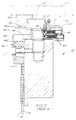
- an electrical terminal applicator includes a frame, generally designated 12, which, in turn, includes an applicator ram housing 12a in which is mounted an applicator ram, generally designated 14, for vertical reciprocating motion within the housing in the direction of double-headed arrow "A".
- An adaptor head 16 projects upwardly of applicator ram 14 for engagement by a press ram 60 ( Figures 2 and 3), as described hereinafter.
- An insulation crimping die 18 projects from the bottom of applicator ram 14, beneath housing 12a, and is juxtaposed with a conductive core crimping die 20 also projecting from the applicator ram beneath housing 12a. Die 18 is positioned forwardly of die 20 when viewed in Figure 1.
- a crimping anvil means, generally designated 22, is located on frame 12 beneath crimping dies 18 and 20.
- applicator ram 14 is drivable by means of press ram 60 (described hereinafter) through a working stroke towards, and a return stroke away from, crimping anvil means 22, as indicated by double-headed arrow "A".
- First or rear crimping die 20 cooperates with anvil means 22 to crimp a first portion of an electrical terminal onto an exposed end of a conductive core of an insulative electrical wire during each downward working stroke of applicator ram 14.
- Second or front crimping die 18 cooperates with anvil means (not shown) to crimp a second portion of the terminal onto the insulation of the electrical wire during each downward working stroke of the applicator ram.
- a terminal strip feed assembly is secured between frame 12 and housing 12a and includes a pivot pin 26, a rocker arm 28 and a feed finger 30 which is loaded by a return spring (not shown).
- the return spring is behind a brace portion 32 of housing 12a and is provided by a torsion coil spring about pin 26.
- the pivot pin is adjustable lengthwise of a slot 34 in brace 32 to determine the end positions of feed finger 30. In other words, adjustment of the location of the pivot point defined by pin 26 adjusts the length of stroke of feed finger 30.
- the pivot pin is adjustable by means of a screw 36.
- Rocker arm 28 is swung about pivot pin 26 by means of a slidable rod 38 (by means not shown) to feed a strip of terminals along a platen 40 in the direction of arrow "B" toward anvil means 22 to locate the leading terminal of the strip on the anvil.
- crimping dies 18 and 20 are effective to crimp the lead terminal onto the stripped end of the insulated electrical wire.
- the press ram/applicator ram are cycled in unison with the operation of rocker arm 28 and feed finger 34 to incrementally advance terminals from the strip thereof to the crimping station defined by anvil means 22 and crimping dies 18 and 20.
- a plurality of adjusting plate means are provided for adjusting the shut heights of crimping die 18 and/or crimping die 20.
- a first adjusting plate means is mounted for angular adjustment about an axis 44 on and extending in the direction of movement of applicator ram 14.
- the first adjusting plate means includes a relatively massive cast circular plate 42a having four pairs of diametrically opposed upwardly directed projections 42b. Both projections of each pair are the same height while each pair is a different height when compared to the other pairs.
- a selected pair of projections is aligned with abutments 56 of a press ram 60 to transmit the crimping force from the press ram to the applicator ram.
- Turning the first adjusting plate 42 changes the height of the projections aligned with the abutments 56 and therefore adjusts the shut height of crimping die 20 which is at a constant or fixed position on applicator ram 14.
- a second adjusting plate means is mounted for angular adjustment about axis 44.
- the second adjusting plate means includes a relatively massive cast circular plate 46a having eight downwardly directed projections 46b of differing heights for interposing between the first adjusting plate and a slide 48 which is positioned adjacent the front or second crimping die 18. Slide 48 is secured to ram 14 by bolt 49.
- first and second adjusting plate means 42 and 46 In operation of first and second adjusting plate means 42 and 46, adjusting plate 42a is rotated to bring a pair of projections 42b into position for effectively adjusting the stroke of the entire applicator ram, including both crimping dies 18 and 20 in response to actuation thereof by the press ram.
- crimping die 20 is provided for crimping the terminal onto the conductive core of the insulated electrical wire.
- second adjusting plate means 46 is provided for that purpose. Specifically, adjusting plate 46a is rotated to bring a projection 46b into alignment with the top of slide 48 which controls the shut height of the front insulation crimping die 18. Therefore, for each increment of adjustment provided by the number of upwardly directed projections 42b of first adjusting plate means 42, additional multiple incremental adjustments are provided by the number of downwardly directed projections 46b of second adjusting plate means 46.
- the invention herein is directed to an improvement in providing fine shut height adjustment for crimping dies 18 and 20, without significantly modifying applicator 10 in the areas of frame 12, housing 12a, terminal strip feed assembly 28, platen 40 and anvil means 22.
- the additional adjusting means of the invention requires modifications only to applicator ram 14 in such a manner that the ram can be replaced by a modified applicator ram, including the adjusting means of the invention, and thereby to retrofit an existing applicator machine.
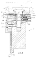
- the invention is embodied in a third adjusting plate means, generally designated 50, and which includes a thin flexible disc 52 mounting a plurality of diskettes 54 of varying thicknesses.
- applicator ram 14' includes an adaptor head 16' at the top thereof, a slide 48' at the side for an insulation crimping die 18', a first adjusting plate means, generally designated 42', a second adjusting plate means, generally designated 46' and crimping die 20'.
- the first adjusting plate means includes upwardly directed projections 42b' for engagement by respective abutments 56 depending downwardly from a pair of opposed claws 58.
- the claws depend from a press ram 60 and embrace adaptor head 16 of the applicator ram.
- Detent means including detent balls 62 and set screws 64, with coil springs 66 sandwiched therebetween, also are shown for indexing first and second adjusting plate means 42' and 46', respectively.
- thin flexible disc 52 of third adjusting plate means 50 is fabricated of flexible sheet metal material and includes ten apertures 70 equally spaced and concentric about a center point 72 of the disc which coincides with axis 44 (Fig. 1) of applicator ram 14. While the first and second adjusting plates 42 and 46 are approximately 5mm thick, disc 52 is only approximately .6mm thick. Each aperture has a plurality of small tabs 76 projecting radially inwardly of the periphery of the aperture. These tabs facilitate snapping diskettes 54 (Figs. 1 and 5) in position within apertures 70, as described hereinafter.
- Figure 4 also shows that a center hole 78 of flexible disc 52 includes a plurality of indexing openings 80 cut into the periphery of the center hole.
- Figures 1 and 4 shows a manually graspable tongue 82 projecting outwardly from the periphery of flexible disc 52 to facilitate manual rotatable adjustment of the disc.
- each diskette 54 has a peripheral groove 84 for receiving tabs 76 within apertures 70 (Fig. 4) of flexible disc 52.
- the lower edge 86 of each diskette 54 is chamfered to ease insertion of the diskette into a respective aperture in the direction of arrow "C" as tabs 76 pass about the diskette and snap into peripheral groove 84 thereof.
- the diskettes are arranged in diametrically opposed pairs on disc 52. Each pair of diskettes 54 are manufactured with a different thickness when compared to the thickness of diskettes of other pairs. It is currently contemplated that such diskettes will range in thickness from 2.96mm to 3.04mm in .02mm increments.
- a detent ball 88 is mounted in a plastic washer 89 positioned in a recessed area 90 of upper adjusting plate 42a of first adjusting plate means 42. Because of the flexibility of disc 52, the disc 52 rides over detent ball 88 until the ball is aligned with one of indexing openings 80 (Fig. 4) to locate the third adjusting plate means 50 in the proper predetermined position with the desired diskettes aligned with the abutments 56 of press ram 60.
- third adjusting plate means 50 can be rotatably adjusted by manually grasping tongue 82 and angularly rotating disk 52 about axis 44 to bring selected ones of diskettes 54 in alignment with the appropriate upwardly directed projections 42b of first adjusting plate means 42 that are to be engaged by abutments 56 of press ram 60.
- a third multiple of adjustments are provided for both crimping dies 18 and 20 by third adjusting plate means 50, without making any modifications to the frame, housing, feeding mechanism and other related components of applicator 10.
- Ram 14' (Fig. 2) only need be replaced by ram 14 (Fig. 3) including third adjusting means 50, in order to retrofit the applicator for a significantly increased range of adjustments.
- disc 52 is described above as being flexible, the fact that groove 84 in each diskette is wider than the thickness of disc 52 permits the diskettes to move relative to the disc. Accordingly, it is contemplated that disc 52 could be manufactured and arranged without being significantly flexible. In such case, a spring would be positioned beneath detent ball 88 to bias the ball upward toward the indexing openings 80 in order to properly align the disc 52.
- the movement of the diskette could be achieved through the use of a relatively flexible disc 92 (Fig. 6).
- the width of groove 94 of diskette 96 would be equal to or greater than the thickness of disc 92.
- the various discs 52 and 92 could be made from plastic or other materials.
- a disc could be made of plastic in the form of rthat shown in Figure 4 or, in the alternative, a plastic disc (not shown) could be overmolded over diskettes 54.
- FIG. 7 Still another embodiment is shown in Figure 7.
- the disc 52 and diskettes 54 are replaced by a single machined disc 96 that is identical to disc 52 except that rather than including diskettes 54, it has generally trapezoidally shaped portions 98.
- Such portions 98 are machined in the same manner as diskettes 54 as described above.
- the portions 98 are machined thin enough so that they are flexible or the intersections between portions 98 and central annular portion 100 are thin enough so as to be flexible in order to permit the portions 98 to move up and down in the same manner as diskettes 54.
- Figures 8-11 show a further embodiment of the invention similar to that of Figures 3-5 and, correspondingly, like reference numerals are applied in at least Figures 8 and 11, corresponding to like components described above in relation to the embodiment of Figures 3-5.
- Figures 8-11 includes a disc assembly, generally designated 102, which includes a first flexible disc 104 corresponding generally in operation and function to disc 52 in the embodiment of Figures 3-5.
- disc assembly 102 includes a second flexible disc 106 juxtaposed on top of disc 104, with the second disc including a plurality of apertures 108 for accommodating the tops of diskettes 54.
- Each diskette again, has a groove 84 which is wider than the thickness of disc 104.
- Figure 9 shows a plan view of first flexible disc 104 which, again, has a manually graspable tongue 110 projecting outwardly from the periphery of the disc to facilitate manual rotatable adjustment of the disc.
- the disc includes ten apertures 112 equally spaced and concentric about a center point 114 of the disc which coincides with axis 44 (Fig. 1) of applicator ram 14.
- Each aperture has a pair of tabs 116 projecting radially inwardly of an inner peripheral portion of the aperture.
- tabs 116 facilitate snapping diskettes 54 in position within apertures 112 as seen in Figures 8 and 11.
- Figure 10 shows a plan view of second flexible disc 106 of disc assembly 102, and the second disc includes a manually graspable tongue 118 projecting outwardly from the periphery of the disc, again to facilitate manual rotatable adjustment of the disc.
- tongue 118 overlies tongue 110
- a plastic handle 120 (Fig. 8) can be press-fit over the juxtaposed tongues.
- second flexible disc 106 is juxtaposed on top of first disc 104, with diskettes 54 projecting through apertures 108 in the second disc as seen clearly in Figure 11.
- the second disc provides a more solid disc assembly and improves manual rotational adjustment by using plastic handle 120.
- the second disc also reduces vibration that may occur during crimping operations.
Landscapes
- Engineering & Computer Science (AREA)
- Mechanical Engineering (AREA)
- Manufacturing & Machinery (AREA)
- Manufacturing Of Electrical Connectors (AREA)
Claims (10)
- Machine de sertissage de bornes électriques (10) qui comprend un coulisseau de machine de sertissage (14) pouvant être entraîné par un coulisseau porte-outil de presse (60) suivant une course de travail vers une enclume de sertissage (22, 26) et une course retour s'en écartant;une matrice de sertissage (18, 20) située sur le coulisseau de machine de sertissage pour, au cours de chaque course de travail du coulisseau de machine de sertissage, coopérer avec l'enclume pour sertir une partie d'une borne électrique sur un fil électrique ; etdes moyens formant plaque de réglage (42, 46) montés sur le coulisseau de machine de sertissage et s'étendant dans sa direction de déplacement pour réglage angulaire autour d'un axe (44), pour interposer de manière sélective un moyen formant saillie entre le coulisseau porte-outil de presse et le coulisseau de machine de sertissage pour régler la hauteur de fermeture de la matrice de sertissage,caractérisée en ce qu'une plaque de réglage flexible (50) est montée pour rotation autour dudit axe pour interposer de manière sélective un moyen formant saillie (54, 98) entre le coulisseau porte-outil de presse et lesdits moyens formant plaque de réglage pour fournir un réglage supplémentaire de la hauteur de fermeture de la matrice de sertissage.
- Machine de sertissage de bornes électriques selon la revendication 1, dans laquelle la plaque flexible comporte une pluralité d'ouvertures (70) agencée en un cercle concentrique autour dudit axe, et dans laquelle ledit moyen formant saillie comprend une pluralité de disquettes (54) d'une épaisseur supérieure à celle de la plaque et montées dans ses ouvertures, les disquettes ayant des épaisseurs différentes pour fournir une plage de réglages.
- Machine de sertissage de bornes électriques selon la revendication 2, dans laquelle ladite plaque flexible (50) comprend une première plaque flexible (104), et comprend une seconde plaque flexible (106) juxtaposée contre la première plaque flexible, la seconde plaque flexible comprenant des ouvertures (108) pour recevoir lesdites disquettes (54).
- Machine de sertissage de bornes électriques selon les revendications 2 ou 3, dans laquelle lesdites ouvertures de la plaque flexible comprennent des petites pattes (76) en saillie de manière radiale vers l'intérieur des périphéries des ouvertures, et dans laquelle chaque disquette comprend un moyen formant évidement de réception de pattes (84) dans sa périphérie, ce par quoi l'on peut encliqueter les disquettes en position dans les ouvertures, les pattes s'encliquetant dans le moyen formant évidement.
- Machine de sertissage de bornes électriques selon la revendication 4, dans laquelle ledit moyen formant évidement comprend une rainure périphérique (84) autour des disquettes (54).
- Machine de sertissage de bornes électriques selon la revendication 5, dans laquelle ladite plaque flexible (50) comprend une première plaque flexible (104), et comprend une seconde plaque flexible (106) juxtaposée contre la première plaque flexible, la seconde plaque flexible comprenant des ouvertures (108) pour recevoir lesdites disquettes (54).
- Machine de sertissage de bornes électriques selon la revendication 2, dans laquelle ladite plaque flexible (50) est fabriquée à partir de matière métallique en feuille.
- Machine de sertissage de bornes électriques selon la revendication 1, comprenant un moyen de détermination de position (80, 88, 89, 90) pour maintenir la plaque flexible dans n'importe laquelle d'une pluralité de positions discrètes de réglage angulaire.
- Machine de sertissage de bornes électriques selon la revendication 8, dans laquelle ledit moyen de détermination de position comprend une pluralité d'ouvertures d'encliquetage (80) dans la plaque flexible et une bille à cliquet (88) pour positionnement dans l'une des ouvertures d'encliquetage.
- Machine de sertissage de bornes électriques selon la revendication 9, dans laquelle ladite plaque flexible (50) comprend, en outre, une poignée en saillie de manière radiale (82) pour permettre la rotation de ladite plaque.
Priority Applications (2)
| Application Number | Priority Date | Filing Date | Title |
|---|---|---|---|
| EP94102752A EP0643457B1 (fr) | 1993-09-14 | 1994-02-24 | Machine de sertissage pour des embouts électriques comportant des moyens d'ajustement améliorés de la hauteur de sertissage |
| US08/289,486 US5517749A (en) | 1993-09-14 | 1994-08-11 | Electrical terminal applicator with improved crimp height adjustment plate means |
Applications Claiming Priority (3)
| Application Number | Priority Date | Filing Date | Title |
|---|---|---|---|
| EP93114720A EP0643456A1 (fr) | 1993-09-14 | 1993-09-14 | Machine du sertissage pour des embouts électriques comportant des moyens d'ajustement de la hauteur de sertissage améliorés |
| EP93114720 | 1993-09-14 | ||
| EP94102752A EP0643457B1 (fr) | 1993-09-14 | 1994-02-24 | Machine de sertissage pour des embouts électriques comportant des moyens d'ajustement améliorés de la hauteur de sertissage |
Publications (2)
| Publication Number | Publication Date |
|---|---|
| EP0643457A1 EP0643457A1 (fr) | 1995-03-15 |
| EP0643457B1 true EP0643457B1 (fr) | 1997-06-11 |
Family
ID=26133415
Family Applications (1)
| Application Number | Title | Priority Date | Filing Date |
|---|---|---|---|
| EP94102752A Expired - Lifetime EP0643457B1 (fr) | 1993-09-14 | 1994-02-24 | Machine de sertissage pour des embouts électriques comportant des moyens d'ajustement améliorés de la hauteur de sertissage |
Country Status (2)
| Country | Link |
|---|---|
| US (1) | US5517749A (fr) |
| EP (1) | EP0643457B1 (fr) |
Families Citing this family (17)
| Publication number | Priority date | Publication date | Assignee | Title |
|---|---|---|---|---|
| US5697146A (en) * | 1994-12-28 | 1997-12-16 | Yazaki Corporation | Apparatus for crimping terminal to electrical wire |
| US6192733B1 (en) * | 1996-07-16 | 2001-02-27 | Alden Owen Long | Two stage press |
| US5909913A (en) * | 1996-09-19 | 1999-06-08 | The Whitaker Corporation | Shut height adjustment mechanism for a terminal applicator |
| US5799391A (en) * | 1996-09-25 | 1998-09-01 | Spring Air . . . Works, Inc. | Apparatus for significantly advancing a carrier strip and crimping various terminal configurations |
| FR2755307B1 (fr) * | 1996-10-31 | 1998-12-24 | Etude Et Realisation De Comple | Dispositif de sertissage polyvalent et son application a une machine a couper et a sertir des fils electriques |
| US6026562A (en) * | 1997-06-25 | 2000-02-22 | General Motors Corporation | Global terminal assembly die |
| US5937510A (en) * | 1997-07-30 | 1999-08-17 | The Whitaker Corporation | Shut height adjustment mechanism for a terminal applicator |
| US5894658A (en) * | 1997-07-31 | 1999-04-20 | The Whitaker Corporation | Terminal applicator having ram retention feature |
| US5845528A (en) * | 1997-10-07 | 1998-12-08 | Artos Engineering Company | Apparatus for crimping terminals on an electrical conductor |
| US6257042B1 (en) | 1999-11-05 | 2001-07-10 | Lillbacka Oy | Open throat crimping machine |
| US6301777B1 (en) | 1999-11-16 | 2001-10-16 | Autoliv Asp, Inc. | Applicator die for wire-to-terminal assembly |
| DE10232470A1 (de) * | 2002-07-17 | 2004-02-05 | Bernhard Schäfer Werkzeug- und Sondermaschinenbau GmbH | Verfahren und Vorrichtung zur Qualitätssicherung von Crimpverbindungen |
| DE102005042450B4 (de) * | 2005-09-06 | 2008-01-17 | Airbus France | Doppelcrimpwerkzeug |
| MX2008004577A (es) | 2005-10-07 | 2008-11-28 | Cti Ind Inc | Aparato, sistema y metodo de aplicador de terminales. |
| GB2453360A (en) * | 2007-10-04 | 2009-04-08 | Deutsch Uk | A wire crimp,a crimping tool and a crimping method |
| CN102000758A (zh) * | 2010-11-19 | 2011-04-06 | 太原重工股份有限公司 | 一种用于锻造液压机的摔圆模 |
| CN112448248B (zh) * | 2020-11-16 | 2021-12-24 | 深圳格力浦电子有限公司 | 一种基片装屏蔽片自动机 |
Family Cites Families (15)
| Publication number | Priority date | Publication date | Assignee | Title |
|---|---|---|---|---|
| US3687069A (en) * | 1971-01-13 | 1972-08-29 | Gulf & Western Ind Prod Co | Shut height counter drive for presses |
| US3911717A (en) * | 1974-01-18 | 1975-10-14 | Itt | Terminal applicator apparatus |
| JPS6031092U (ja) * | 1983-08-09 | 1985-03-02 | シ−ケ−デイ株式会社 | 端子圧着機 |
| AU568883B2 (en) * | 1983-10-31 | 1988-01-14 | Hashimoto Forming Industry Co. Limited | Press machine |
| DE3704904A1 (de) * | 1987-02-17 | 1988-08-25 | Grote & Hartmann | Crimphoehenverstellvorrichtung fuer eine crimpmaschine |
| US4790173A (en) * | 1987-05-29 | 1988-12-13 | Amp Incorporated | Shut height adjustment means in pressing apparatus |
| US4970889A (en) * | 1989-05-12 | 1990-11-20 | Amp Incorporated | Crimping machine having improved adjusting system |
| GB8917144D0 (en) * | 1989-07-27 | 1989-09-13 | Amp Gmbh | Press ram |
| US5074033A (en) * | 1989-10-10 | 1991-12-24 | Acu-Crimp, Inc. | Applicator die |
| US5275032A (en) * | 1990-05-30 | 1994-01-04 | The Whitaker Corporation | Method and apparatus for controlling the crimp height of crimped electrical connections |
| GB9012073D0 (en) * | 1990-05-30 | 1990-07-18 | Amp Gmbh | Electrical terminal applicator and a crimp height adjustment plate therefor |
| GB9012058D0 (en) * | 1990-05-30 | 1990-07-18 | Amp Gmbh | Method of,and apparatus for,controlling the crimp height of crimped electrical connections |
| DE4039051A1 (de) * | 1990-11-30 | 1992-06-17 | Bernhard Schaefer Werkzeug Und | Vorrichtung zum verbinden eines drahtes mit einem kontaktelement od. dgl. |
| DE4137163A1 (de) * | 1991-11-12 | 1993-05-13 | Bernhard Schaefer Werkzeug Und | Vorrichtung zum verbinden eines drahtes mit einem stecker, kontaktelement o. dgl. |
| US5323634A (en) * | 1993-05-14 | 1994-06-28 | The Whitaker Corporation | Shut height adjustment device having replaceable spacers |
-
1994
- 1994-02-24 EP EP94102752A patent/EP0643457B1/fr not_active Expired - Lifetime
- 1994-08-11 US US08/289,486 patent/US5517749A/en not_active Expired - Lifetime
Also Published As
| Publication number | Publication date |
|---|---|
| US5517749A (en) | 1996-05-21 |
| EP0643457A1 (fr) | 1995-03-15 |
Similar Documents
| Publication | Publication Date | Title |
|---|---|---|
| EP0643457B1 (fr) | Machine de sertissage pour des embouts électriques comportant des moyens d'ajustement améliorés de la hauteur de sertissage | |
| US4025999A (en) | Adjustable crimp die assembly | |
| DE60103588T2 (de) | Vorrichtung zum Anpressen von Kabelendklemmen | |
| US5095599A (en) | Electrical terminal applicator and a crimp height adjustment plate therefor | |
| US6736664B2 (en) | Piercing terminal and machine and method for crimping piercing terminal | |
| EP0533315B1 (fr) | Chassis et matrisse de sertissage pour applicateur de borne | |
| US5909913A (en) | Shut height adjustment mechanism for a terminal applicator | |
| US5289713A (en) | Device for connecting a wire to a plug, contact element or the like with crimp height adjustment | |
| US4707913A (en) | Terminal applicator having quick-adjust connecting link | |
| EP0525952A2 (fr) | Dispositif d'alimentation d'une bande pour applicateur de borne | |
| US4534107A (en) | Wire insertion and terminal crimping tool | |
| US5937510A (en) | Shut height adjustment mechanism for a terminal applicator | |
| US5483739A (en) | Electrical terminal applicator with improved crimp height adjustment plate means | |
| US7254981B2 (en) | Crimping apparatus | |
| DE3240376C3 (de) | Druckschalter | |
| DE3425473C2 (de) | Mehrfachschalter mit drehbarem Schaltglied | |
| US6951160B2 (en) | Cutting device for spring manufacturing machines | |
| EP0624457B1 (fr) | Dispositif de réglage de la position basse du coulisseau avec écarteurs remplaçables | |
| EP0643456A1 (fr) | Machine du sertissage pour des embouts électriques comportant des moyens d'ajustement de la hauteur de sertissage améliorés | |
| DE19534611A1 (de) | Kippschalter | |
| GB2266253A (en) | Machine for attaching terminals to conductors | |
| US5577318A (en) | Electrical terminal applicator with improved track adjustment means | |
| WO1998000892A1 (fr) | Mecanisme d'alimentation pour applicateur de bornes electriques | |
| EP1223646A2 (fr) | Dispositif de sertissage de terminaux sur un câble | |
| KR960007868Y1 (ko) | 단자압착기 |
Legal Events
| Date | Code | Title | Description |
|---|---|---|---|
| PUAI | Public reference made under article 153(3) epc to a published international application that has entered the european phase |
Free format text: ORIGINAL CODE: 0009012 |
|
| AK | Designated contracting states |
Kind code of ref document: A1 Designated state(s): DE ES FR GB GR IE IT NL PT |
|
| 17P | Request for examination filed |
Effective date: 19950826 |
|
| GRAG | Despatch of communication of intention to grant |
Free format text: ORIGINAL CODE: EPIDOS AGRA |
|
| RAP1 | Party data changed (applicant data changed or rights of an application transferred) |
Owner name: MOLEX INCORPORATED |
|
| 17Q | First examination report despatched |
Effective date: 19960813 |
|
| GRAH | Despatch of communication of intention to grant a patent |
Free format text: ORIGINAL CODE: EPIDOS IGRA |
|
| ITF | It: translation for a ep patent filed |
Owner name: DE DOMINICIS & MAYER S.R.L. |
|
| GRAH | Despatch of communication of intention to grant a patent |
Free format text: ORIGINAL CODE: EPIDOS IGRA |
|
| GRAA | (expected) grant |
Free format text: ORIGINAL CODE: 0009210 |
|
| AK | Designated contracting states |
Kind code of ref document: B1 Designated state(s): DE ES FR GB GR IE IT NL PT |
|
| PG25 | Lapsed in a contracting state [announced via postgrant information from national office to epo] |
Ref country code: NL Free format text: LAPSE BECAUSE OF FAILURE TO SUBMIT A TRANSLATION OF THE DESCRIPTION OR TO PAY THE FEE WITHIN THE PRESCRIBED TIME-LIMIT Effective date: 19970611 Ref country code: GR Free format text: LAPSE BECAUSE OF FAILURE TO SUBMIT A TRANSLATION OF THE DESCRIPTION OR TO PAY THE FEE WITHIN THE PRESCRIBED TIME-LIMIT Effective date: 19970611 Ref country code: ES Free format text: THE PATENT HAS BEEN ANNULLED BY A DECISION OF A NATIONAL AUTHORITY Effective date: 19970611 |
|
| REF | Corresponds to: |
Ref document number: 69403743 Country of ref document: DE Date of ref document: 19970717 |
|
| ET | Fr: translation filed | ||
| PG25 | Lapsed in a contracting state [announced via postgrant information from national office to epo] |
Ref country code: PT Effective date: 19970911 |
|
| NLV1 | Nl: lapsed or annulled due to failure to fulfill the requirements of art. 29p and 29m of the patents act | ||
| PGFP | Annual fee paid to national office [announced via postgrant information from national office to epo] |
Ref country code: IE Payment date: 19980126 Year of fee payment: 5 |
|
| PLBE | No opposition filed within time limit |
Free format text: ORIGINAL CODE: 0009261 |
|
| STAA | Information on the status of an ep patent application or granted ep patent |
Free format text: STATUS: NO OPPOSITION FILED WITHIN TIME LIMIT |
|
| 26N | No opposition filed | ||
| PG25 | Lapsed in a contracting state [announced via postgrant information from national office to epo] |
Ref country code: IE Free format text: LAPSE BECAUSE OF NON-PAYMENT OF DUE FEES Effective date: 19990224 |
|
| REG | Reference to a national code |
Ref country code: GB Ref legal event code: IF02 |
|
| PG25 | Lapsed in a contracting state [announced via postgrant information from national office to epo] |
Ref country code: IT Free format text: LAPSE BECAUSE OF NON-PAYMENT OF DUE FEES Effective date: 20050224 |
|
| PGRI | Patent reinstated in contracting state [announced from national office to epo] |
Ref country code: IT Effective date: 20080301 |
|
| PGFP | Annual fee paid to national office [announced via postgrant information from national office to epo] |
Ref country code: IT Payment date: 20080228 Year of fee payment: 15 Ref country code: GB Payment date: 20080227 Year of fee payment: 15 |
|
| PGFP | Annual fee paid to national office [announced via postgrant information from national office to epo] |
Ref country code: FR Payment date: 20080218 Year of fee payment: 15 Ref country code: DE Payment date: 20080331 Year of fee payment: 15 |
|
| GBPC | Gb: european patent ceased through non-payment of renewal fee |
Effective date: 20090224 |
|
| REG | Reference to a national code |
Ref country code: FR Ref legal event code: ST Effective date: 20091030 |
|
| PG25 | Lapsed in a contracting state [announced via postgrant information from national office to epo] |
Ref country code: DE Free format text: LAPSE BECAUSE OF NON-PAYMENT OF DUE FEES Effective date: 20090901 |
|
| PG25 | Lapsed in a contracting state [announced via postgrant information from national office to epo] |
Ref country code: GB Free format text: LAPSE BECAUSE OF NON-PAYMENT OF DUE FEES Effective date: 20090224 Ref country code: FR Free format text: LAPSE BECAUSE OF NON-PAYMENT OF DUE FEES Effective date: 20090302 |
|
| PG25 | Lapsed in a contracting state [announced via postgrant information from national office to epo] |
Ref country code: IT Free format text: LAPSE BECAUSE OF NON-PAYMENT OF DUE FEES Effective date: 20090224 |