EP0641178B1 - Chirurgisches nähinstrument - Google Patents
Chirurgisches nähinstrument Download PDFInfo
- Publication number
- EP0641178B1 EP0641178B1 EP93909763A EP93909763A EP0641178B1 EP 0641178 B1 EP0641178 B1 EP 0641178B1 EP 93909763 A EP93909763 A EP 93909763A EP 93909763 A EP93909763 A EP 93909763A EP 0641178 B1 EP0641178 B1 EP 0641178B1
- Authority
- EP
- European Patent Office
- Prior art keywords
- jaw
- displaceable
- outer tube
- instrument
- jaws
- Prior art date
- Legal status (The legal status is an assumption and is not a legal conclusion. Google has not performed a legal analysis and makes no representation as to the accuracy of the status listed.)
- Expired - Lifetime
Links
Images





Classifications
-
- A—HUMAN NECESSITIES
- A61—MEDICAL OR VETERINARY SCIENCE; HYGIENE
- A61B—DIAGNOSIS; SURGERY; IDENTIFICATION
- A61B17/00—Surgical instruments, devices or methods
- A61B17/28—Surgical forceps
- A61B17/29—Forceps for use in minimally invasive surgery
- A61B17/2909—Handles
-
- A—HUMAN NECESSITIES
- A61—MEDICAL OR VETERINARY SCIENCE; HYGIENE
- A61B—DIAGNOSIS; SURGERY; IDENTIFICATION
- A61B17/00—Surgical instruments, devices or methods
- A61B17/04—Surgical instruments, devices or methods for suturing wounds; Holders or packages for needles or suture materials
- A61B17/0469—Suturing instruments for use in minimally invasive surgery, e.g. endoscopic surgery
-
- A—HUMAN NECESSITIES
- A61—MEDICAL OR VETERINARY SCIENCE; HYGIENE
- A61B—DIAGNOSIS; SURGERY; IDENTIFICATION
- A61B17/00—Surgical instruments, devices or methods
- A61B17/04—Surgical instruments, devices or methods for suturing wounds; Holders or packages for needles or suture materials
- A61B17/0482—Needle or suture guides
-
- A—HUMAN NECESSITIES
- A61—MEDICAL OR VETERINARY SCIENCE; HYGIENE
- A61B—DIAGNOSIS; SURGERY; IDENTIFICATION
- A61B17/00—Surgical instruments, devices or methods
- A61B17/04—Surgical instruments, devices or methods for suturing wounds; Holders or packages for needles or suture materials
- A61B17/0467—Instruments for cutting sutures
-
- A—HUMAN NECESSITIES
- A61—MEDICAL OR VETERINARY SCIENCE; HYGIENE
- A61B—DIAGNOSIS; SURGERY; IDENTIFICATION
- A61B17/00—Surgical instruments, devices or methods
- A61B17/32—Surgical cutting instruments
- A61B17/320016—Endoscopic cutting instruments, e.g. arthroscopes, resectoscopes
-
- A—HUMAN NECESSITIES
- A61—MEDICAL OR VETERINARY SCIENCE; HYGIENE
- A61B—DIAGNOSIS; SURGERY; IDENTIFICATION
- A61B17/00—Surgical instruments, devices or methods
- A61B17/04—Surgical instruments, devices or methods for suturing wounds; Holders or packages for needles or suture materials
- A61B17/06—Needles ; Sutures; Needle-suture combinations; Holders or packages for needles or suture materials
- A61B17/06066—Needles, e.g. needle tip configurations
- A61B2017/06076—Needles, e.g. needle tip configurations helically or spirally coiled
-
- A—HUMAN NECESSITIES
- A61—MEDICAL OR VETERINARY SCIENCE; HYGIENE
- A61B—DIAGNOSIS; SURGERY; IDENTIFICATION
- A61B17/00—Surgical instruments, devices or methods
- A61B17/28—Surgical forceps
- A61B17/29—Forceps for use in minimally invasive surgery
- A61B2017/2926—Details of heads or jaws
Definitions
- the invention relates to a surgical sewing instrument according to the preamble of the first claim.
- Such a surgical sewing instrument is known from US 4,935,027 (Yoon).
- This sewing instrument is suitable for both conventional and minimally invasive (MIC) surgery. It consists of an outer and an inner tube, which are axially displaceable relative to one another, from whose distal ends (facing away from the surgeon, to be inserted into the body of a patient) protrude two pliers or tweezers-like jaws or hooks that are hollow and in the cavity of which Material is guided.
- the document shows that both jaws or hooks can be movable or one jaw is fixed and only the other is movable.
- the jaws or hooks are moved via the handle.
- the feed for the sewing material is located within the inner tube.
- This sewing instrument only single button seams can be created, whereby each seam must be secured with a knot that can be moved towards the fabric.
- the creation of the nodes appears complicated and time-consuming.
- the fabric is not only pierced by the sewing material, but also by the hooks.
- a surgical instrument for applying clips is known from DE 31 41 647 A1.
- This instrument contains an elongated body with a handle on the proximal end. At the distal end of the body there is a fixed support jaw with a matrix. A cavity is provided in the die to close the brackets.
- a movable pressure jaw with a clip opener is arranged at the distal end of the body. The pressure jaw is fastened to the body so that it can move back and forth in the direction of the die mentioned.
- the instrument has a drive for adjusting the pressure jaw and the clip opener.
- the movable pressure jaw contains a channel for feeding the wire.
- a knife is arranged to be movable back and forth in the direction perpendicular to the outlet end of the channel. The knife is used to cut pieces of wire and is kinematically connected to the above-mentioned drive.
- the known instrument is not suitable for minimally invasive surgery because of its construction and size.
- Another sewing instrument is known from EP 0 174 843 A2.
- This sewing instrument consists of a block that encloses a cavity that is open on one side.
- a sewing material holding device is integrated into the cavity and can be actuated via a handle at the proximal end.
- a channel also opens into the cavity and receives a needle with an eye, with the sewing material running through the eye.
- the channel lies opposite the material holding device.
- a suction device opens into the cavity.
- the block is placed on the tissue to be sewn in such a way that the cavity is closed off by the tissue.
- the cavity is then evacuated via the suction device, so that the tissue enters the cavity in a double layer.
- the sewing instrument is only suitable for sewing over closed tissue, since it is only in this case that it can be brought into the cavity with the aid of the suction device. It is not possible to treat wound edges.
- a surgical instrument for creating sutures which is intended in particular for sewing on pacemakers.
- This instrument contains an instrument shaft that has a proximal and distal, has an end to be inserted into a patient's body.
- Two channels run in the instrument shaft, which receive sections of a wire-shaped material.
- the channels are shaped at the distal end of the instrument shaft in such a way that the material to be sewn is given an annular shape.
- the pacemaker lead is attached to the distal end of the instrument shaft at the start of the operation.
- a two-piece handle is used to feed the material and to release the electrode.
- the instrument has no jaws; with it, wound edges can therefore only be sewn in favorable cases.
- US 1,449,087 describes a forceps-like sewing device with two distal curved jaws, each of which has a clamping surface. There is a curved channel in each jaw, which ends in the clamping surface. A surgical sewing needle with sutures is pushed by means of a plunger along the curved channels through the tissue located between the clamping surfaces.
- EP-A-0 121 362 discloses a stapling device in which a straight piece of stiff suture material, which is arranged displaceably in a channel of a first jaw, is bent approximately in a circular manner in a curved channel of a second opposing jaw.
- the invention has for its object to avoid the disadvantages of the known instruments and in particular to propose a surgical sewing instrument of the type mentioned, the jaws of which do not pierce the tissue and with the help of which several seams can be created in one operation.
- the instrument is said to be able to sew wound edges in both conventional surgery and minimally invasive surgery. It should therefore be able to be carried out and operated by a trocar sleeve.
- tissue edges can be fixed after a lesion or incision.
- the two tissue edges to be connected are approximated either with a pair of pliers or with a special embodiment of the sewing instrument according to the invention described in more detail below and brought into contact with one another in such a way that the two surfaces of the tissue adjacent to the wound edges lie on the same side touch.
- the seam is applied in the double layer of the adjacent fabric, which projects approximately perpendicularly in the manner of a fabric fold from the surface of the remaining fabric.
- the fabric edges lying on top of each other are gripped with the two jaws of the sewing instrument according to the invention.
- the two jaws can assume a position in which they are approximately parallel to one another at a distance from one another which corresponds approximately to twice the thickness of the fabric to be sewn. This position is referred to below as the working position.
- a single or double row seam can be placed in the working position.
- the two jaws in their opposite sides, starting from the channel for feeding the sewing material, contain a plurality of grooves spaced apart from one another, both in the movable jaw and in the fixed jaw, the base surfaces of which lie on a helix in the working position.
- the sewing material Due to the distal displacement of the sewing material in the channel, the sewing material is pushed out of the end of the channel in the fixed jaw, pierces the double-layered fabric and finally reaches the first groove of the movable jaw, where it is deflected and when the material is pushed forward ( with a sufficiently large barrel depth), the double-layered tissue pierces again. Then its tip meets the first groove of the fixed jaw, where the sewing material is continued on a screw line.
- the material to be sewn is preferably moved from the proximal to the distal end in suitable, constructive means in individual, short steps with the aid of the handle.
- the length of the individual steps depends on the strength of the sewing material used.
- Thin metal wire made of stainless steel, tantalum etc. is preferably used.
- Metal wires of this type are sufficiently stiff that they are less prone to tilting or bending inside the feed channel; they can also be used to pierce the tissue without any additional devices.
- the device according to the invention can also be operated with another, sufficiently stiff sewing material.
- the individual steps should be chosen to be so short - according to the mechanical strength of the sewing material used - that the sewing material does not become jammed within the channel and the fabric pierces without bending; however, they should be as long as is possible under these conditions in order to keep the time required for the distal advancement of the sewing material during the operation within reasonable limits. If a stainless steel wire with a diameter of 0.25 mm is used as the sewing material, the individual steps can be about 3 mm long.
- the channel preferably contains a locking device which acts on the material to be sewn and which prevents the material from being moved proximally by releasing the material to be sewn only when it is moved distally.
- a locking device which acts on the material to be sewn and which prevents the material from being moved proximally by releasing the material to be sewn only when it is moved distally.
- An embodiment is particularly preferred in which the blocking effect, for. B. to change the material from the handle from the surgeon.
- the movable jaw should preferably be able to be moved both towards and away from the fixed jaw from the working position. In the working position, the two jaws are approximately parallel to each other. Your distance becomes constructive predetermined and is essentially determined by the double thickness of the tissue to be sewn.
- the position in which the movable jaw is folded away from the fixed jaw is referred to below as the rest position.
- the rest position By moving from the working position to the rest position and back, the layers of tissue to be sewn can be gripped and released again.
- the sewing material is brought into a helical or helical shape, because during sewing, the sewing material, starting from the mouth of the channel which guides the sewing material and which is arranged in the fixed jaw, is passed through the grooves in the two Cheeks guided and shaped.
- the tissue to be sewn is pierced either only when the material to be sewn passes from the fixed jaw to the movable jaw or additionally (if there is sufficient grip depth) during the transition from the movable jaw to the fixed jaw.
- the guiding and shaping of the sewing material as well as the punctures through the fabric create a frictional force that can increase sharply with the number of screw lines or helices.
- This frictional force can be greatly reduced by moving the movable jaw from the working position towards the fixed jaw.
- the path that the movable jaw travels is preferably a few tenths of a millimeter. This movement causes the diameter of the spiral of the material to be reduced slightly. Therefore, the movable jaw should be moved during the sewing process at the end of each feed step via the handle from the working position towards the fixed jaw. The sewing material is then no longer in the working position of the jaws firmly on the bottom of the grooves, so that the friction is reduced during further feed.
- the friction can be further reduced during the operation by adding a suitable lubricant.
- Such lubricants such. B. silicone oil are known and are already used in conventional sewing instruments.
- the finished seam can also be secured by moving the movable jaw from the working position towards the fixed jaw. After the sewing process has been completed and the material has been cut off, the movable jaw is opened to the rest position, whereby the fabric and the seam are released. The coil of the material to be sewn is then gripped and pressed together with the tips of the jaws, the movable jaw being moved towards the fixed jaw into the working position. This prevents the seam from opening.
- an embodiment is particularly preferred in which the tips of the jaws are profiled on their opposite sides in the distal area in front of the grooves.
- a preferred profiling consists of closely adjacent depressions that are parallel to the grooves, i. H. are attached at the same angle to the axis of the outer tube and their distances correspond to 1 / n of the distances between the grooves; n represents an integer.
- the outer tube may be provided with two opposite notches at its distal end. These indentations are made in such a way that the outer tube moves relative to the axis during its distal axial movement Instrument shaft and thus to the jaws does not come into contact with the tissue to be sewn and injures it.
- Such notches are preferably arranged symmetrically to a plane that is parallel to the side of the fixed jaw that is opposite the movable jaw.
- the shape of the notches can be varied within wide limits depending on the design of the sewing instrument according to the invention.
- the outer tube may be tapered distally in such a way that the fixed jaw is no longer gripped.
- the distal end of the outer tube and the edges of the notches can also be rounded in a known manner in order to further reduce the risk of tissue damage.
- the feed of the sewing material during sewing is facilitated if the grooves at the ends that are reached by the sewing material are widened in a funnel shape. This prevents the material from tilting at the grooves.
- the material to be sewn can be separated with the aid of a movable carriage with a cutting edge which is attached to the fixed jaw and which is moved by a lever on the proximal side of the device.
- the movable jaw is preferably moved away from the fixed jaw from the working position in the following way: On the movable jaw, a part with a V-shaped cross-section and with its apex edge pointing to the fixed jaw is attached within the outer tube.
- a V-shaped part z. B. a cylindrical sector body can be used.
- the apex edge of the V-shaped part runs transversely to the axis of the outer tube and is mounted in a recess in the instrument shaft which extends transversely to the axis of the outer tube.
- the outer tube At the distal end of the outer tube is a pin on the side opposite the fixed jaw attached such that by proximally displacing the outer tube relative to the jaws, the distal side surface of the cross-sectionally V-shaped part is displaced proximally by the pin, whereby the apex edge rotates in the recess and the movable jaw moves away from the fixed jaw.
- the outer tube is axially displaceable relative to the instrument shaft via the handle.
- the movement of the movable jaw in the direction of the fixed jaw preferably takes place in that the outer tube is pushed in the distal direction over the movable jaw.
- the working position, d. H. the parallel position of the jaws is reached.
- the further movement of the movable jaw from the working position towards the fixed jaw is preferably achieved by a bulge which is provided on the outer lateral surface of the movable jaw and over which the outer tube is pushed in a further distal movement.
- One of the jaws of the surgical sewing instrument according to the invention e.g. B. the fixed, can wear on its opposite side of the other jaw a pointed mandrel which engages in the working position of the jaws in the other jaw in a correspondingly shaped recess.
- grasping forceps for holding the tissue edges can be dispensed with during sewing.
- the jaws When the jaws are at rest, the mandrel is guided at a suitable point under the first edge of the fabric.
- the jaws To load the tissue on the mandrel, the jaws are brought into the working position, the tissue being perforated by the mandrel. Then the movable jaw is raised again (brought into the rest position) and the second tissue edge is gripped in the same way.
- the mandrel in the proximal area of the jaws e.g. B. is arranged behind the mouth of the channel for the sewing material, so only one additional puncture must be tolerated per sewing operation.
- the thorn is in the distal Area at the top of the jaws, better visibility makes it easier to grip the wound edges. In this case, a further puncture must be tolerated during the final deformation of the helical material.
- the distal end of the outer tube 21 with the enclosed instrument shaft 20 is inserted into the patient's body through a 10 mm trocar sleeve.
- the movable jaw 24 folded up in the rest position is brought into the working position parallel to the fixed jaw 23 by a short path on the finger part 1 of the handle 1, 2 and the translatory movement of the outer tube 21 coupled therewith.
- the construction of the instrument is chosen so that the distance between the hand-held fixed handle part 2 and the two jaws 23, 24 remains constant to facilitate precise manipulation in the operating field.
- the movable jaw 24 is actuated, only the outer tube is axially displaced, so that no compensating hand movement by the surgeon is required to maintain a desired spatial position of the jaws 23, 24.
- the distal end of the instrument consists of the two jaws 23, 24.
- the jaw 23, referred to as fixed, is produced by appropriately shaping the distal end of the instrument shaft (FIGS. 1 and 6).
- FIGS. 3a and 3b The construction of the jaw 24 and the guidance of the sewing material 17 can be seen from FIGS. 3a and 3b.
- the fulcrum of the second, movable jaw 24 lies in a recess 46 of the instrument shaft 20 behind the fixed jaw 23.
- the movable jaw 24 is opened by a pin 35 in the outer tube 21, which is displaceable on the instrument shaft 20, while the closing by sliding over the upper distal front edge of the outer tube 21 on the outer cheek surface. Securing the position of the movable jaw 24 relative to the fixed jaw 23 is only ensured by the geometry of its inclusion, namely by the position in the recess 46 of the instrument shaft 20 and by the embedding in the outer tube 21. Pins and connecting or bearing bolts were used dispensed with, since they are difficult to attach due to their necessarily small dimensions and are often overloaded.
- the helical seam spiral is generated step by step by repeatedly pressing the handle 1, 2 (Fig. 1).
- the spiral with a circular cross-section has an outer diameter of 4 mm for a material made of 0.25 mm thick wire.
- the wire 17 is provided in the region of the guide channel 43, which lies in the fixed jaw 23 and in the movable slide 45 First an arc formation in a plane parallel to the instrument's longitudinal axis.
- the radius of this arc is somewhat larger than the radius of the finished coil for reasons of space (accommodating the movable slide 45 in the fixed jaw 23), so that the final radius shaping of the wire 17 in the movable jaw 24 can only take place after the first tissue puncture.
- the corresponding inlets 50 of the guide grooves 38 are flared (see FIG. 3b).
- z working strokes with parallel jaws 23, 24 are required.
- the number z is a function of the desired seam length or the desired number of stitches or turns and the selected stroke of the wire feed.
- the handle 1, 2 is tightened until the working area "spiral constriction" stops.
- the thumb-reachable lever 11 on the handle head 18 (see FIG. 1) is released for actuation.
- the movable slide 45 in the dovetail groove 51 of the fixed jaw 23 is shifted proximally, the wire 17 in the shear eye 55 is sheared off at the shear edge 41, and the end of the coil through the rounded upper edge of the slide 45 into the plane of the inner jaw surfaces 36, 40 bent.
- This measure serves as well as a corresponding wire shaping at the "head end" of a complete seam to secure against "unwinding" of the helix after opening the movable jaw 24 e.g. for repositioning the jaws 23, 24.
- This repositioning is provided in order - if necessary - to deform the circular helical cross section in the post-forming region of the front jaw region in a flat oval shape. The result is an increase in security against "opening" of the seam.
- the instrument shaft 20 is surrounded by the outer tube 21, which can be moved axially on the instrument shaft by actuating the handle 1, 2.
- the instrument shaft 20 which is formed at the distal end for the fixed jaw and for supporting the movable jaw, there are the longitudinal grooves 51, 53 for receiving and guiding the movable carriage 45 and its connecting rod 56 for driving the Carriage of the shearing device and the longitudinal groove 34 for guiding the support tube 27 for the sewing wire 17. Furthermore, a pocket 48 for receiving a spring-loaded brake shoe 58 is present in this instrument part in the course of the square guide channel 43 of the wire - in the advancing direction close to the fixed jaw 23 .
- the sewing wire (0.25 mm ⁇ ) must be secured against buckling by the instrument shaft 20 to the end of the guide channel 43 be pushed in the fixed jaw 23.
- it is kept free of kinks during the feed in a wire support tube 27 (FIGS. 2 and 3a) with an outer diameter of 1.5 mm and an inner diameter of 0.4 mm.
- the wire support tube 27 is welded to the clamping sleeve 28 of the feed mechanism and is moved back and forth in the groove 34 of the instrument shaft 20 in accordance with the selected feed.
- the surgeon can - e.g. B. to change the sewing material 17 - by means of a plug pin in the bore 60 of the brake shoe 58 and a corresponding bore in the outer tube 21, create a coupling between these parts and release the locking action by actuating the handle 1, 2.
- the movable slide 45 and the connecting rod 56 (FIG. 3b, FIG. 7) of the slide drive are made in one piece from partially hardenable stainless steel sheet. Due to the geometrical conditions in the handle head 18, an offset in the connecting rod 56 led to a change of sides from the upper slide part 45 in the fixed jaw 23 to the slide drive in a pocket 59 of the handle head 18.
- the stage piece 63 in the connecting rod 56 (FIG. 7) is designed to be relatively long in order to be able to compensate for the directional torques which occur under load by small supporting forces between the guide cams 47 of this part and the inner wall of the outer tube 21.
- the transverse opening 64 for the level piece 63 has been extended proximally in view of the assembly by the length of the dovetail groove 51 in the fixed jaw 23.
- the two handle parts 1, 2 are maximally spread in the normal position in the rest position by two flat springs 3, 4 arranged between them.
- the hand area of the finger grip part 1 is designed to be grip-friendly in the usual shape.
- the fork 5 adjoining at the top is articulated to form the bearing point with the bearing pin 6 on the handle head 18. Furthermore, the upper ends of the fork 5 are connected in an articulated manner to the rectangular flange 22 welded to the proximal end of the outer tube 21 by screws with a stepped shaft 7.
- the shafts of the screws 7 slide in the translatory displacement of the outer tube 21 in elongated holes 8 at the fork end.
- the fork cheek facing the thumb-actuated lever 11 is partially thickened.
- This blocking block 9 serves in the normal working area of the handle 1, 2 as a safeguard against inadvertent actuation of the movable slide 45.
- Both parts lie in a stepped bore 66 of the grip head 18 in an axially aligned extension of the wire guide channel 43, 14 in the inner part of the instrument shaft 21.
- the outer jacket of the clamping sleeve 28 carries two conical bores 30, 32 at a distance of 3 mm in the longitudinal direction, which are connected to one another by a less deep triangular groove 31.
- a flat spring-loaded pin 49 in the grip head 18 fixes the clamping sleeve 28 in a force-fitting and form-fitting manner in accordance with the positions of the conical bores 30, 32 in the jacket of the sleeve 28.
- the spring-loaded pin 49 slides through the connecting groove 31 between the bores 30, 32 and thus prevents twisting of the sleeve 28 and thus undesirable torsion of the wire 17.
- the distance between the bores 30, 32 in the jacket defines the wire feed path.
- other scenes with different distances can be attached in the same way next to each other on the sleeve shell. The desire for a longer or shorter feed path can then be met by simply turning the sleeve on other slide tracks.
- the clamping bolt 14 is initially divided axially. After the prismatic inner grooves 33a, 33b have been milled, both halves 14.1, 14.2 are welded to one another in the axis of the clamping bolt 14. Cone 44 - and thread end 65 can be slightly bent open in order to achieve a safe wire release in the clamping area 33a or a frictional nut block on the thread 65.
- a strong helical compression spring 13 is arranged between the adjusting nut 15 (FIG. 4; for fine adjustment of the spring force) on the thread 65 of the clamping bolt 14 and the banquet of the offset receiving bore 66 for the feed mechanism 14, 28 (see FIG. 2).
- the clamping bolt 14 In the rest position of the instrument, it presses the clamping bolt 14 outward, thereby releasing the clamping bolt cone 44 from the wire 17 and pulling the clamping sleeve 28 back so far that the spring-loaded locking pin 49 in the distal conical one Bore 30 snaps into the sleeve casing 28.
- the movable jaw When the handle 1, 2 is actuated from its rest position, the movable jaw is first brought into the parallel working position, as described. Then the free travel adjusting nut 16 on the coupling rod 19 in the grip head 18 presses against the clamping nut 15 of the clamping bolt 14. The cone 44 of the clamping bolt 14 moves into the clamping sleeve 28, is compressed and clamps in its axial prismatic channel 33a through the central bore of the clamping nut 15 fed wire 17 fixed. When the thrust force is increased further, the locking pin 49 in the grip head 18 is lifted out of the distal bore 30 in the clamping sleeve 28 against the pressure of the flat spring 54.
- the clamping sleeve 28, including the clamping bolt 14 and sewing wire 17, is moved distally - secured against rotation by the pin in the triangular groove 31 between the bores 30, 32 - until the pin 49 in the proximal depression 32 of the link 30, 31 at the end of the feed path , 32 engages.
- a retraction of the sewing wire 17 during this process due to the friction between the wire and the wire support tube 27 is prevented by the brake shoe 58 acting self-locking on the drawn wire 17 in the vicinity of the shoe.
- the handle 1, 2 After resetting the movable slide 45 via the lever 68 loaded by the spring 47, the handle 1, 2 can be opened up to the end stop. As a result, the movable jaw moves in the rest position.
- the jaws 23, 24 can be closed again in their front region for the flat oval shaping of the helix. This closing movement only takes place within the scope of the freewheel path, i.e. without activating the clamping and feed mechanism.
- the inner surfaces 36, 40 in the distal part of the jaws 23, 24 are profiled by depressions 62.
Landscapes
- Health & Medical Sciences (AREA)
- Surgery (AREA)
- Life Sciences & Earth Sciences (AREA)
- Medical Informatics (AREA)
- Nuclear Medicine, Radiotherapy & Molecular Imaging (AREA)
- Engineering & Computer Science (AREA)
- Biomedical Technology (AREA)
- Heart & Thoracic Surgery (AREA)
- Molecular Biology (AREA)
- Animal Behavior & Ethology (AREA)
- General Health & Medical Sciences (AREA)
- Public Health (AREA)
- Veterinary Medicine (AREA)
- Ophthalmology & Optometry (AREA)
- Surgical Instruments (AREA)
- Materials For Medical Uses (AREA)
Description
- Die Erfindung betrifft ein chirurgisches Nähinstrument gemäß dem Oberbegriff des ersten Patentanspruchs.
- Ein solches chirurgisches Nähinstrument ist aus der US 4,935,027 (Yoon) bekannt. Dieses Nähinstrument ist sowohl für die konventionelle als auch für die minimalinvasive (MIC) Chirurgie geeignet. Es besteht aus einem äußeren und einem inneren Rohr, die gegeneinander axial verschiebbar sind, aus deren distalen (dem Operateur abgewandten, in den Körper eines Patienten einzuführenden) Enden zwei zangen- oder pinzettenartige Backen oder Haken hervorragen, die hohl sind und in deren Hohlraum das Nähgut geführt wird. Aus der Druckschrift geht hervor, daß beide Backen oder Haken beweglich sein können oder die eine Backe feststeht und nur die andere beweglich ist. Am proximalen (dem Operateur zugewandten) Ende befindet sich ein Griffstück, das teilweise mit dem äußeren Rohr und teilweise mit dem inneren Rohr fest verbunden ist. Über das Griffstück werden die Backen oder Haken bewegt. Innerhalb des inneren Rohrs befindet sich die Zuführung für das Nähgut. Mit diesem Nähinstrument können lediglich Einzelknopfnähte angelegt werden, wobei jede Naht mit einem auf das Gewebe hin verschiebbaren Knoten gesichert werden muß. Die Anlage der Knoten erscheint kompliziert und zeitaufwendig. Ferner wird das Gewebe nicht nur vom Nähgut, sondern auch von den Haken durchstochen.
- Aus der DE 31 41 647 A1 ist ein chirurgisches Instrument zum Anlegen von Klammern bekannt. Dieses Instrument enthält einen langgestreckten Körper mit einem Handgriff am proximalen Ende. Am distalen Ende des Körpers ist eine feststehende Stützbacke mit einer Matrize angeordnet. In der Matrize ist eine Aushöhlung zum Klammerschluß vorgesehen. Weiterhin ist am distalen Ende des Körpers eine bewegliche Andrückbacke mit einem Klammeraufschieber angeordnet. Die Andrückbacke ist am Körper in Richtung der genannten Matrize hin- und hergehend bewegbar befestigt. Ferner weist das Instrument einen Antrieb zum Verstellen der Andrückbacke und des Klammeraufschiebers auf. Die bewegliche Andrückbacke enthält einen Kanal für die Zuführung des Drahts. An der Andrückbacke ist ein Messer in zum Austrittsende des Kanals rechtwinkliger Richtung hin- und hergehend bewegbar angeordnet. Das Messer dient zum Abtrennen von Drahtstücken und ist mit dem obengenannten Antrieb kinematisch verbunden.
- Das bekannte Instrument ist für die minimalinvasive Chirurgie wegen seiner Konstruktion und Größe nicht geeignet.
- Ein weiteres Nähinstrument ist aus der EP 0 174 843 A2 bekannt. Dieses Nähinstrument besteht aus einem Block, der einen einseitig offenen Hohlraum umschließt. In den Hohlraum ist eine Nähgut-Haltevorrichtung integriert, die über ein Griffstück am proximalen Ende betätigt werden kann. In den Hohlraum mündet ferner ein Kanal, der eine Nadel mit einem Öhr aufnimmt, wobei das Nähgut durch das Öhr läuft. Der Kanal liegt der Nähgut-Haltevorrichtung gegenüber. Weiterhin mündet in den Hohlraum eine Saugvorrichtung. Der Block wird so auf das zu vernähende Gewebe aufgesetzt, daß der Hohlraum durch das Gewebe abgeschlossen wird. Anschließend wird der Hohlraum über die Saugvorrichtung evakuiert, so daß das Gewebe in einer doppelten Lage in den Hohlraum eintritt. Danach wird mit Hilfe der Nadel und der Nähgut-Haltevorrichtung eine Naht angelegt und schließlich die Saugvorrichtung belüftet, so daß das Gewebe die ursprüngliche Lage wieder einnimmt. Das Nähinstrument ist nur zum Übernähen von geschlossenem Gewebe geeignet, da es nur in diesem Fall mit Hilfe der Saugvorrichtung in den Hohlraum gebracht werden kann. Eine Versorgung von Wundrändern ist nicht möglich.
- Ferner ist aus der DE 29 27 143 A1 ein chirurgisches Instrument zur Anlage von Nähten bekannt, das insbesondere zum Annähen von Herzschrittmachern dienen soll. Dieses Instrument enthält einen Instrumentenschaft, der ein proximales und distales, in den Körper eines Patienten einzuführendes Ende aufweist. Im Instrumentenschaft verlaufen zwei Kanäle, die Abschnitte eines drahtförmigen Nähguts aufnehmen. Die Kanäle sind am distalen Ende des Instrumentenschafts in der Weise geformt, daß dem Nähgut eine Ringform verliehen wird. Die Elektrode des Herzschrittmachers ist zu Beginn der Operation am distalen Ende des Instrumentenschafts befestigt. Ein zweiteiliges Griffstück dient dem Vorschub des Nähguts und dem Lösen der Elektrode. Das Instrument enthält keine Backen; mit ihm können Wundränder daher allenfalls in günstigen Fällen vernäht werden.
- Die US 1,449,087 beschreibt eine zangenartige Nähvorrichtung mit zwei distalen gekrümmten Backen, die jeweils eine Klemmfläche aufweisen. In jeder Backe ist ein gekrümmter Kanal vorhanden, der in der Klemmfläche endet. Mittels eines Kolbens wird eine chirurgische Nähnadel mit Nahtmaterial entlang der gekrümmten Kanäle durch das zwischen den Klemmflächen befindliche Gewebe geschoben.
- Die EP-A-0 121 362 offenbart eine Klammervorrichtung, in der ein gerades Stück steifes Nahtmaterial, welches in einem Kanal einer ersten Klemmbacke verschiebbar angeordnet ist, in einem gekrümmten Kanal einer zweiten gegenüberliegenden Klemmbacke etwa kreisringförmig gebogen wird.
- Der Erfindung liegt die Aufgabe zugrunde, die Nachteile der bekannten Instrumente zu vermeiden und insbesondere ein chirurgisches Nähinstrument der eingangs genannten Art vorzuschlagen, dessen Backen das Gewebe nicht durchstechen und mit dessen Hilfe mehrere Nähte in einem Arbeitsgang angelegt werden können. Mit dem Instrument sollen sich Wundränder sowohl in der konventionellen Chirurgie als auch in der minimalinvasiven Chirurgie vernähen lassen. Es soll daher durch eine Trokarhülse durchführbar und bedienbar sein.
- Die Aufgabe wird erfindungsgemäß durch die im Kennzeichen des ersten Patentanspruchs beschriebenen Merkmale gelöst. In den weiteren Ansprüchen sind vorteilhafte Ausgestaltungen des erfindungsgemäßen chirurgischen Nähinstruments beschrieben.
- Mit dem erfindungsgemäßen chirurgischen Nähinstrument können Geweberänder nach einer Läsion oder Inzision fixiert werden. Hierzu werden die beiden zu verbindenden Geweberänder entweder mit einer Faßzange oder mit einer besonderen, im folgenden näher beschriebenen Ausführungsform des erfindungsgemäßen Nähinstruments approximiert und in der Weise miteinander in Kontakt gebracht, daß die beiden auf der gleichen Seite liegenden Flächen des an die Wundränder angrenzenden Gewebes einander berühren. Die Naht wird in der Doppellage des angrenzenden Gewebes angelegt, das annähernd senkrecht in der Art einer Gewebefalte von der Oberfläche des übrigen Gewebes absteht.
- Mit den beiden Backen des erfindungsgemäßen Nähinstruments werden die aufeinander liegenden Geweberänder gefaßt. Die beiden Backen können eine Position einnehmen, in der sie annähernd parallel zueinander in einem solchen Abstand voneinander stehen, der etwa der doppelten Dicke des zu vernähenden Gewebes entspricht. Diese Position wird im folgenden als Arbeitsstellung bezeichnet. Je nach Faßtiefe kann in der Arbeitsstellung eine ein- oder doppelreihige Naht gelegt werden.
- Die beiden Backen enthalten in ihren einander gegenüberliegenden Seiten ausgehend von dem Kanal zur Zuführung des Nähguts sowohl in der beweglichen Backe als auch in der feststehenden Backe mehrere im Abstand zu einander angeordnete Nuten, deren Grundflächen in der Arbeitsstellung auf einer Schraubenlinie liegen.
- Durch die distale Verschiebung des Nähguts in dem Kanal wird das Nähgut aus dem Ende des Kanals in der feststehenden Backe vorgeschoben, durchstößt das doppelt gelegte Gewebe und gelangt schließlich in die erste Nut der beweglichen Backe, wo es umgelenkt wird und beim weiteren Vorschieben des Nähguts (bei ausreichend großer Faßtiefe) das doppelt gelegte Gewebe erneut durchstößt. Danach trifft dessen Spitze die erste Nut der feststehenden Backe, wo das Nähgut auf einer Schraubenlinie weitergeführt wird.
- Wenn das Nähgut alle Nuten durchlaufen hat, hat es daher eine schraubenlinien- oder wendelartige Form angenommen. Die Achse der Nähgut-Wendel liegt parallel zu den Wundrändern. Je nach Faßtiefe durchstößt jede Windung der Wendel das Gewebe einoder zweimal, so daß eine einreihige oder zweireihige Naht entsteht. Nach der Fertigstellung der Naht wird das Nähgut abgetrennt und gegen ein Abgleiten vom Gewebe gesichert. Der beschriebene Vorgang wiederholt sich, bis die Geweberänder vollständig miteinander vernäht sind.
- Vorzugsweise wird das Nähgut innerhalb des Kanals durch geeignete konstruktive Mittel in einzelnen, kurzen Schritten mit Hilfe des Griffstücks vom proximalen zum distalen Ende bewegt. Die Länge der einzelnen Schritte hängt von der Festigkeit des verwendeten Nähguts ab. Vorzugsweise wird dünner Metalldraht aus Edelstahl, Tantal etc. verwendet. Metalldrähte dieser Art sind ausreichend steif, so daß sie weniger zum Verkanten oder Umbiegen innerhalb des Zuführungskanals neigen; mit ihnen kann außerdem das Gewebe ohne weitere Hilfsvorrichtungen durchstochen werden. Die erfindungsgemäße Vorrichtung kann jedoch auch mit einem anderen, ausreichend steifen Nähgut betrieben werden. Die einzelnen Schritte sollen - entsprechend der mechanischen Belastbarkeit des verwendeten Nähguts - so kurz gewählt werden, daß sich das Nähgut innerhalb des Kanals nicht verkantet und das Gewebe durchsticht, ohne sich umzubiegen; sie sollen jedoch so lang sein, wie unter diesen Bedingungen möglich ist, um den Zeitbedarf für das distale Vorschieben des Nähguts während der Operation in angemessenen Grenzen zu halten. Wenn als Nähgut ein Edelstahldraht mit einem Durchmesser von 0,25 mm verwendet wird, können die einzelnen Schritte etwa 3 mm lang sein.
- Vorzugsweise enthält der Kanal eine Sperrvorrichtung, die auf das Nähgut einwirkt und die ein proximales Rückverschieben des Nähguts verhindert, indem das Nähgut nur freigegeben wird, wenn es distal bewegt wird. Besonders bevorzugt ist eine Ausführungsform, bei der die Sperrwirkung z. B. zum Wechseln des Nähguts vom Griffstück aus vom Chirurgen aufgehoben werden kann.
- Die bewegliche Backe soll vorzugsweise von der Arbeitsstellung aus sowohl auf die feststehende Backe zu als auch von ihr weg bewegt werden können. In Arbeitsstellung liegen die beiden Backen annähernd parallel zueinander. Ihr Abstand wird konstruktiv vorgegeben und wird im wesentlichen von der doppelten Dicke des zu vernähenden Gewebes bestimmt.
- Die Position, in der die bewegliche Backe von der feststehenden Backe weggeklappt ist, wird im folgenden als Ruhestellung bezeichnet. Durch die Bewegung von der Arbeitsstellung in die Ruhestellung und zurück können die zu vernähenden Lagen des Gewebes ergriffen und wieder freigegeben werden.
- Die Möglichkeit, die bewegliche Backe ausgehend von der Arbeitsstellung in Richtung auf die feststehende Backe bewegen zu können, ist aus folgenden Gründen vorteilhaft:
- Während des distalen Vorschubs des Nähguts beim Nähvorgang wird das Nähgut in eine schraubenlinien- oder wendelartige Form gebracht, denn beim Nähen wird das Nähgut, ausgehend von der in der feststehenden Backe angeordneten Mündung des Kanals, der das Nähgut führt, durch die Nuten in den beiden Backen geführt und geformt. Hierbei wird, wie erwähnt, das zu vernähende Gewebe entweder nur beim Übergang des Nähguts von der feststehenden Backe zur beweglichen Backe oder zusätzlich (bei ausreichender Faßtiefe) beim Übergang von der beweglichen Backe zur feststehenden Backe durchstochen. Die Führung und Formung des Nähguts sowie die Durchstiche durch das Gewebe bewirken eine Reibungskraft, die mit der Zahl der Schraubenlinien oder Wendeln stark ansteigen kann.
- Diese Reibungskraft kann durch die Bewegung der beweglichen Backe aus der Arbeitsstellung in Richtung auf die feststehende Backe stark vermindert werden. Der Weg, den die bewegliche Backe hierbei zurücklegt, beträgt vorzugsweise einige Zehntel Millimeter. Diese Bewegung bewirkt, daß der Durchmesser der Wendel des Nähguts geringfügig reduziert wird. Deshalb soll die bewegliche Backe während des Nähvorgangs am Ende eines jeden Vorschubschritts über das Griffstück aus der Arbeitsstellung in Richtung auf die feststehende Backe bewegt werden. In Arbeitsstellung der Backen liegt danach das Nähgut nicht mehr fest auf dem Grund der Nuten auf, so daß die Reibung beim weiteren Vorschub reduziert ist. Die Reibung kann während der Operation durch Zugabe eines geeigneten Gleitmittels zusätzlich vermindert werden. Solche Gleitmittel wie z. B. Siliconöl sind bekannt und werden bei üblichen Nähinstrumenten bereits verwendet.
- Durch die Bewegung der beweglichen Backe aus der Arbeitsstellung in Richtung auf die feststehende Backe kann außerdem die fertiggestellte Naht gesichert werden. Nach Beendigung des Nähvorgangs und nach dem Abtrennen des Nähguts wird die bewegliche Backe in die Ruhestellung aufgeklappt, wodurch das Gewebe und die Naht freigegeben werden. Danach wird die Wendel des Nähguts mit den Spitzen der Backen ergriffen und zusammengedrückt, wobei die bewegliche Backe bis in die Arbeitsstellung auf die feststehende Backe zubewegt wird. Hierdurch wird das Aufgehen der Naht verhindert.
- Zur Vereinfachung dieses Vorgangs wird eine Ausführungsform besonders bevorzugt, bei der die Spitzen der Backen auf ihren einander gegenüberliegenden Seiten im distalen Bereich vor den Nuten profiliert sind. Eine bevorzugte Profilierung besteht aus eng benachbarten Einsenkungen, die parallel zu den Nuten, d. h. im selben Winkel gegenüber der Achse des äußeren Rohres, angebracht sind und deren Abstände 1/n der Abstände zwischen den Nuten entsprechen; n stellt eine ganze Zahl dar. Mit Hilfe dieser Einsenkungen kann die fertiggestellte Wendel des Nähguts besonders sicher erfaßt werden, da die Windungen der Wendel jeweils in einzelne dieser Einsenkungen eingreifen und von diesen abgestützt werden, so daß die Wendel nicht abgleitet und sich nicht unkontrolliert verformt.
- Je nach Ausführungsform des erfindungsgemäßen Nähinstruments kann es sinnvoll sein, das äußere Rohr an seinem distalen Ende mit zwei einander gegenüberliegenden Einkerbungen zu versehen. Diese Einkerbungen werden in der Art angebracht, daß das äußere Rohr bei seiner distalen axialen Bewegung relativ zum Instrumentenschaft und damit zu den Backen nicht mit dem zu vernähenden Gewebe in Kontakt kommt und dieses verletzt. Solche Einkerbungen werden vorzugsweise symmetrisch zu einer Ebene angeordnet, die parallel zu derjenigen Seite der feststehenden Backe verläuft, die der beweglichen Backe gegenüber liegt. Die Form der Einkerbungen kann je nach Ausführung des erfindungsgemäßen Nähinstruments in weiten Grenzen variiert werden. Unter Umständen kann das äußere Rohr distal in der Weise abgeschrägt sein, daß die feststehende Backe nicht mehr umfaßt wird.
- Das distale Ende des äußeren Rohres und die Ränder der Einkerbungen können zudem in bekannter Weise abgerundet werden, um die Gefahr einer Verletzung des Gewebes weiter zu vermindern.
- Der Vorschub des Nähguts beim Nähen wird erleichtert, wenn die Nuten an den Enden, die vom Nähgut zuerst erreicht werden, trichterförmig erweitert sind. Hierdurch wird ein Verkanten des Nähguts an den Nuten verhindert.
- Nach Fertigstellung einer Naht kann das Nähgut mit Hilfe eines beweglichen Schlittens mit einer Schneidkante, der in der feststehenden Backe angebracht ist und der von einem Hebel an der proximalen Seite der Vorrichtung aus bewegt wird, abgetrennt werden.
- Vorzugsweise wird die bewegliche Backe in folgender Weise aus der Arbeitsstellung von der feststehenden Backe wegbewegt: An der beweglichen Backe ist innerhalb des äußeren Rohres ein im Querschnitt V-förmiges, mit seiner Scheitelkante auf die feststehende Backe weisendes Teil angebracht. Als V-förmiges Teil kann z. B. ein zylindersektorförmiger Körper verwendet werden. Die Scheitelkante des V-förmigen Teils verläuft quer zur Achse des äußeren Rohres und ist in einer quer zur Achse des äußeren Rohres verlaufenden Ausnehmung im Instrumentenschaft gelagert. Am distalen Ende des äußeren Rohres ist auf der der feststehenden Backe gegenüberliegenden Seite ein Stift derart angebracht, daß durch proximales Verschieben des äußeren Rohres relativ zu den Backen die distale Seitenfläche des im Querschnitt V-förmigen Teils durch den Stift proximal verschoben wird, wodurch sich die Scheitelkante in der Ausnehmung dreht und sich die bewegliche Backe von der feststehenden Backe entfernt. Das äußere Rohr ist über das Griffstück gegenüber dem Instrumentenschaft axial verschiebbar.
- Die Bewegung der beweglichen Backe in Richtung der feststehenden Backe erfolgt vorzugsweise dadurch, daß das äußere Rohr in distaler Richtung über die bewegliche Backe geschoben wird. Hierdurch wird wieder die Arbeitsstellung, d. h. die parallele Stellung der Backen, erreicht. Die weitere Bewegung der beweglichen Backe aus der Arbeitsstellung auf die feststehende Backe zu wird vorzugsweise durch eine Aufwölbung erreicht, die auf der äußeren Mantelfläche der beweglichen Backe vorgesehen wird und über die das äußere Rohr in einer weiteren distalen Bewegung geschoben wird.
- Eine der Backen des erfindungsgemäßen chirurgischen Nähinstruments, z. B. die feststehende, kann auf ihrer der anderen Backe gegenüberliegenden Seite einen spitzen Dorn tragen, der in Arbeitsstellung der Backen in der jeweils anderen Backe in eine entsprechend geformte Vertiefung eingreift.
- Mit einem derart modifizierten Instrument kann während des Nähens auf eine Faßzange zum Halten der Geweberänder verzichtet werden. Der Dorn wird in Ruhestellung der Backen an einer geeigneten Stelle unter den ersten Geweberand geführt. Zum Aufladen des Gewebes auf den Dorn werden die Backen in die Arbeitsstellung gebracht, wobei das Gewebe durch den Dorn perforiert wird. Danach wird die bewegliche Backe wieder angehoben (in Ruhestellung gebracht) und in der gleichen Weise der zweite Geweberand erfaßt. Wenn der Dorn im proximalen Bereich der Backen, z. B. hinter der Mündung des Kanals für das Nähgut angeordnet ist, so muß pro Nähvorgang lediglich ein zusätzlicher Durchstich toleriert werden. Wenn der Dorn im distalen Bereich an der Spitze der Backen angeordnet ist, erleichtern bessere Sichtverhältnisse das Greifen der Wundränder. In diesem Fall muß bei der abschließenden Deformation des wendelförmigen Nähguts ein weiterer Durchstich toleriert werden.
- Die Erfindung wird im folgenden anhand von Figuren, in denen eine besondere Ausführungsform des erfindungsgemäßen chirurgischen Nähinstruments dargestellt ist, näher erläutert.
- Es zeigen
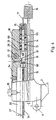
- Fig. 1
- eine Gesamtansicht einer Ausführungsform des erfindungsgemäßen Nähinstruments;
- Fig. 2
- den Kanal für das Nähgut und die Vorrichtung zu dessen distalem Vorschub;
- Fig. 3a
- das distale Ende des Instruments mit den Backen und der Sperrvorrichtung;
- Fig. 3b
- die feststehende Backe mit dem beweglichen Schlitten der Schneidvorrichtung in Aufsicht;
- Fig. 4
- den Griffkopf im Teilschnitt;
- Fig. 5
- eine weitere Ansicht des Griffkopfs;
- Fig. 6
- den Instrumentenschaft;
- Fig. 7
- die Schneidvorrichtung.
- Die gezeigte Ausführungsform des erfindungsgemäßen Nähinstruments ist für einen Edelstahldraht von 0,25 mm Durchmesser als Nähgut konzipiert; sie besteht aus drei Baugruppen:
- dem Arbeitskopf mit den Backen 23, 24 und der Schervorrichtung 45 für das Nähgut 17,
- dem Griffstück 1, 2 bestehend aus Griffkopf 18 mit starr angeschlossenem Handtellerteil 2 und dem relativ hierzu beweglichen Fingerteil 1 und
- dem Instrumentenschaft 20, der die Verbindung zwischen den Backen 23, 24 und dem Handtellerteil 2 darstellt, sowie dem äußeren Rohr 21 zur Betätigung der beweglichen Backe 24 vom Fingerteil 1 aus.
- Ferner kann zwischen folgenden Funktionen unterschieden werden, die mit Teilen ihrer mechanischen Realisierung z. T. in allen drei Baugruppen zu finden sind:
- Betätigung der beweglichen Backe 24,
- Ausführungsform mit zusätzlichem Dorn: Aufladen und Zusammenführen der Geweberänder,
- Formen des Nähguts 17 zu einer Wendel 26,
- Verminderung des Durchmessers der Wendel des Nähguts 17 z. B. nach jedem Vorschubschritt zur Verminderung der Reibung zwischen Nähgut 17 und den formgebenden und führenden Nuten 38 in den Backen 23, 24,
- wiederholtes Klemmen und anschließender schrittweiser Vorschub des Nähguts 17 durch die Vorschubvorrichtung 14, 28,
- selbsthemmende Arretierung des Drahts 17 gegen Rückzug in der Sperrvorrichtung 57, 58 und bei der Repositionierung der Klemm- und Vorschubeinrichtung 14, 28 in die Ausgangsstellung,
- Trennen des z. B. von der Rolle ablaufenden Nähguts am Nahtende durch den beweglichen Schlitten 45,
- Umbiegen des Nähguts 17 am Nahtanfang und -ende zum Gewebe hin, um nach dem Aufklappen der beweglichen Backe 24 den Drahtrückzug ins Gewebe und das Aufgehen der gesetzten Naht vor der abschließenden Sicherung zu erschweren,
- Formen des Nähgut-Anfangs beim Abschneiden, so daß die Durchstichkraft minimiert wird und beim Gewebedurchstich auf die Spitze des Nähguts eine Führungskraft zur Wendelachse hin erzeugt wird,
- Verformung des zunächst kreisförmigen Nähgutwendel-Querschnitts in ein flaches Oval als Sicherung gegen Aufziehen der Naht,
- Sicherung der Schermechanik 45 gegen unbeabsichtigte Betätigung und
- Modifizierung der Funktionssequenzen durch verschiedene Stellschrauben 15, 16 bei vorgegebener Betätigung des Griffstücks 1, 2.
- Das distale Ende des äußeren Rohres 21 mit dem umfaßten Instrumentenschaft 20 wird durch eine 10 mm - Trokarhülse in den Körper des Patienten eingeführt. Dazu wird während des Durchschiebens die in Ruhestellung hochgeklappte bewegliche Backe 24 durch einen kurzen Weg am Fingerteil 1 des Griffstücks 1, 2 und der damit gekoppelten translatorischen Bewegung des äußeren Rohres 21 in die Arbeitsstellung parallel zur feststehenden Backe 23 gebracht.
- Alle übrigen Instrumentenfunktionen werden dabei wegen eines einstellbaren Leerweges in der Koppelmechanik nicht aktiviert.
- Die Konstruktion des Instruments ist so gewählt, daß zur Erleichterung einer exakten Manipulation im Operationsfeld der Abstand zwischen dem handgeführten festen Griffteil 2 und den beiden Backen 23, 24 konstant bleibt. Beim Betätigen der beweglichen Backe 24 wird lediglich das äußere Rohr axial verschoben, so daß zur Beibehaltung einer gewünschten räumlichen Position der Backen 23, 24 keine kompensierende Handbewegung des Chirurgen erforderlich ist.
- Das distale Ende des Instruments besteht aus den beiden Backen 23, 24. Die als feststehend bezeichnete Backe 23 wird durch entsprechende Formung des distalen Endes des Instrumentenschafts hergestellt (Fig. 1 und 6).
- Die Konstruktion der Backe 24 und die Führung des Nähguts 17 sind aus den Fig. 3a und 3b ersichtlich.
- Der Drehpunkt der zweiten, beweglichen Backe 24 liegt in einer Ausnehmung 46 des Instrumentenschafts 20 hinter der feststehenden Backe 23.
- Das Aufklappen der beweglichen Backe 24 geschieht durch einen Stift 35 in dem auf dem Instrumentenschaft 20 verschiebbaren äußerem Rohr 21, während das Zuklappen durch das Übergleiten der oberen distale Vorderkante des äußeren Rohrs 21 auf die äußere Backenfläche erfolgt. Die Positionssicherung der beweglichen Backe 24 relativ zur festen Backe 23 ist nur durch die Geometrie ihres Einschlusses gewährleistet, und zwar durch die Lage in der Ausnehmung 46 des Instrumentenschafts 20 und durch die Einbettung in das äußere Rohr 21. Auf Stifte und Verbindungs- oder Lagerbolzen wurde verzichtet, da sie aufgrund ihrer notwendigerweise kleinen Abmessungen schwierig anzubringen und häufig überlastet sind.
- Wie bereits erwähnt, werden die beiden aufeinanderliegenden Geweberänder so mit den Backen 23, 24 gefaßt, daß
- entweder nur eine Durchstichreihe dicht hinter ihnen entsteht und das fortlaufende Nähgut 17 außen an ihnen vorbeiläuft oder daß
- bei weiterem Übergreifen der Backen 23, 24 zwei parallele Durchstichreichen erzeugt werden und der Nähdraht nur noch an der Ober- und Unterseite der Naht sichtbar bleibt.
- Die schraubenförmige Nahtwendel wird schrittweise durch mehrmaliges Betätigen des Griffstücks 1, 2 (Fig. 1) erzeugt. Die Wendel mit Kreisquerschnitt hat bei einem Nähgut aus 0,25 mm starkem Draht einen Außendurchmesser von 4 mm.
- Über einen weiter unten beschriebenen Drahtklemm- und Vorschubmechanismus 14, 28 (vgl. Fig. 2) wird, nachdem die bewegliche Backe 24 in Arbeitsposition gebracht wurde, der Draht durch weiteres Zusammendrücken des Griffstücks 1, 2 aus dem Führungskanal 43 distal zur Mündung in der festen Backe 23 vorgeschoben. Der Vorschub erfolgt schrittweise mit jeweils 3 mm. Das Nähgut 17 tritt zunächst durch einen der Wendelsteigung angepaßten Schlitz 55 des beweglichen Schlittens 45 in der festen Backe 23 hindurch.
- In dem Bereich des Führungskanals 43, der in der festen Backe 23 und im beweglichen Schlitten 45 liegt, erhält der Draht 17 zunächst eine Bogenformung in einer Ebene parallel zur Instrumentenlängsachse. Der Radius dieses Bogens ist aus Platzgründen (Unterbringung des beweglichen Schlittens 45 in der festen Backe 23) etwas größer als der Radius der fertigen Wendel, so daß erst nach dem ersten Gewebedurchstich die endgültige Radiusformung des Drahtes 17 in der beweglichen Backe 24 stattfinden kann.
- Am Ende jedes Drahtvorschub- und Formungstaktes läuft das distale Ende des äußeren Rohres 21 auf eine exzentrisch auf dem Mantel der beweglichen Backe liegenden, aufgewölbten Querrippe 37. Dadurch werden die Backen 23, 24 jeweils 0,3 mm enger zusammengeführt, was eine entsprechende Durchmesserreduzierung der Nahtwendel zur Folge hat.
- Diese Maßnahme ist erforderlich, um ein Festlaufen der gebildeten Wendel in den Führungsnuten 38 der Backen 23, 24 infolge der Gesetzmäßigkeit

- S2 = Vorschubkraft für den Draht [N]
- S1 = Reibungs- und Widerstandskraft an der Drahtspitze [N]
- µ = Reibungskoeffizient zwischen Draht und Führungsnut[-]
- α = Berührungswinkel von Draht und Nut [rad]
- Um ein sicheres Einspuren der Drahtspitze nach jedem Gewebedurchstich zu fördern, sind die entsprechenden Einläufe 50 der Führungsnuten 38 konisch erweitert (siehe Fig. 3b).
- Zur vollständigen oder teilweisen Ausführung der Wendelnaht 26 sind z Arbeitshübe bei parallel liegenden Backen 23, 24 erforderlich. Die Zahl z ist eine Funktion der gewünschten Nahtlänge bzw. der gewünschten Stich- oder Windungszahl und des gewählten Hubs des Drahtvorschubes.
- Am Ende jeder Teilnaht wird das Griffstück 1,2 bis zum Anschlag des Arbeitsbereiches "Wendelverengung" angezogen. Damit wird der daumenerreichbare Hebel 11 am Griffkopf 18 (vgl. Fig. 1) zur Betätigung freigegeben. Durch Niederdrücken dieses Hebels 11 wird der bewegliche Schlitten 45 in der Schwalbenschwanznut 51 der festen Backe 23 nach proximal verschoben, der Draht 17 im Scherauge 55 an der Scherkante 41 abgeschert und das Wendelende durch die verrundete Oberkante des Schlittens 45 in die Ebene der Backeninnenflächen 36, 40 umgebogen.
- Diese Maßnahme dient ebenso wie eine entsprechende Drahtformung am "Kopfende" einer vollständigen Naht der Sicherung gegen "Aufziehen" der Wendel nach Öffnen der beweglichen Backe 24 z.B. zum Umsetzen der Backen 23, 24. Dieses Umsetzen ist vorgesehen, um - falls erforderlich - den kreisrunden Wendelquerschnitt im Nachformungsbereich des vorderen Backenbereichs flachoval zu verformen. Das Ergebnis ist eine Erhöhung der Sicherheit gegen "Aufziehen" der Naht.
- Beim Trennen des Drahtes 17 am Wendelende wird durch Formgebung der Schneidkante 52 in der festen Backe - zwei Schneiden im Winkel von 60° zueinander - der Drahtanfang unter den gegebenen Möglichkeiten so geformt, daß
- der Durchstichwiderstand im Gewebe möglichst klein ist und
- beim Gewebedurchstich eine Kraftkomponente in radialer Richtung zur Wendelachse hin auftritt, die ein zentrifugales Ausbrechen des Drahtes 17 infolge des aufbiegenden Momentes verhindert.
- Wie bereits beschrieben, wird der Instrumentenschaft 20 vom äußeren Rohr 21 umgeben, das durch Betätigen des Griffstücks 1,2 axial auf dem Instrumentenschaft verschiebbar ist.
- Im Instrumentenschaft 20 (siehe Fig. 6), der am distalen Ende zur festen Backe und zur Lagerung der beweglichen Backe ausgebildet ist, befinden sich die Längsnuten 51, 53 für die Aufnahme und Führung des beweglichen Schlittens 45 und und seiner Verbindungsstange 56 zum Antrieb des Schlittens der Schervorrichtung sowie die Längsnut 34 zur Führung des Stützröhrchens 27 für den Nähdraht 17. Ferner ist in diesem Instrumententeil im Verlauf des quadratischen Führungskanals 43 des Drahtes - in Vorschubrichtung dicht vor der festen Backe 23 - eine Tasche 48 zur Aufnahme einer federbelasteten Bremsbacke 58 vorhanden.
- Da die Drahtklemm- und Vorschubeinrichtung 14, 28 (vgl. hierzu Fig. 2) aus Platzgründen im Griffkopf 18 des Instrumentes untergebracht ist, muß der Nähdraht (0,25 mm ⌀) gegen Ausknicken gesichert durch den Instrumentenschaft 20 bis zum Ende des Führungskanals 43 in der festen Backe 23 geschoben werden. Zu diesem Zweck wird er während des Vorschubes in einem Drahtstützrohr 27 (Fig. 2 und 3a) mit 1,5 mm Außendurchmesser und 0,4 mm Innendurchmesser knickfrei gehalten. Das Drahtstützrohr 27 ist mit der Klemmhülse 28 der Vorschubmechanik verschweißt und wird entsprechend dem gewählten Vorschub translatorisch in der Nut 34 des Instrumentenschaftes 20 hin und her bewegt.
- Beim Zurückfahren des Drahtstützrohres 27 verhindert die federbelastete Bremsbacke 58 (Fig. 3a) durch Eintritt von Selbsthemmung ein Zurückziehen des Nähdrahtes 17 infolge der Reibung an der Rohrinnenwand und im gelösten Klemmbolzen 14 (Fig. 1, 4 bzw. 14.1, 14.2 in Fig. 2).
- Der Chirurg kann - z. B. zum Wechseln des Nähguts 17 - durch einen Steckstift in der Bohrung 60 der Bremsbacke 58 und einer entsprechenden Bohrung im äußeren Rohr 21 eine Kopplung zwischen diesen Teilen herstellen und durch Betätigen des Griffstücks 1, 2 die Sperrwirkung aufheben.
- Der bewegliche Schlitten 45 und die Verbindungsstange 56 (Fig. 3b, Fig 7) des Schlittenantriebes sind einteilig aus partiell härtbarem nichtrostendem Stahlblech gefertigt. Bedingt durch die geometrischen Gegebenheiten im Griffkopf 18 wurde durch einen Versatz in der Verbindungsstange 56 ein Seitenwechsel vom Schlittenoberteil 45 in der festen Backe 23 zum Schlittenantrieb in einer Tasche 59 des Griffkopfes 18 realisiert. Das Etagenstück 63 in der Verbindungsstange 56 (Fig. 7) ist relativ lang ausgeführt, um die bei Belastung auftretenden Richtmomente durch kleine Stützkräfte zwischen den Führungsnocken 47 dieses Teiles und der Innenwand des äußeren Rohres 21 kompensieren zu können. Der Querdurchbruch 64 für das Etagenstück 63 ist mit Rücksicht auf die Montage um die Länge der Schwalbenschwanznut 51 in der festen Backe 23 nach proximal erweitert.
- Das Griffstück 1, 2 (vgl. Fig. 1, 4 und 5) des Nähinstruments besteht aus
- dem Griffkopf 18,
- dem relativ zu ihm beweglichen Fingergriffteil 1 und
- dem über den Griffkopf 18 starr mit dem Instrumentenschaft 20 verbundenen Handteller-Griffteil 2.
- Die beiden Griffteile 1, 2 werden durch zwei zwischen ihnen angeordnete Flachfedern 3, 4 in üblicher Weise in Ruhestellung maximal gespreizt.
- Der Griffkopf 18 dient
- zur beweglichen Lagerung des Fingergriffteiles 1,
- Unterbringungen der Klemm- und Vorschubeinrichtung 14, 28 für den Nähdraht 17,
- zur Installation des Schlittenantriebes und
- zur Verbindung des Handteller-Griffteiles 2 mit dem Instrumentenschaft 20.
- Der Handbereich des Fingergriffteiles 1 ist in üblicher Formgebung griffsympatisch ausgeführt. Die sich nach oben anschließende Gabel 5 ist zur Bildung der Lagerstelle mit dem Lagerzapfen 6 am Griffkopf 18 gelenkig verschraubt. Ferner sind die oberen Enden der Gabel 5 gelenkig mit dem am proximalen Ende des äußeren Rohres 21 angeschweißten Rechteckflansch 22 durch Schrauben mit abgesetztem Schaft 7 verbunden. Die Schäfte der Schrauben 7 gleiten bei der translatorischen Verschiebung des äußeren Rohres 21 in Langlöchern 8 am Gabelende. Die dem daumenbetätigten Hebel 11 zugewandte Gabelwange ist partiell verdickt. Diese Blockadekulisse 9 dient im normalen Arbeitsbereich des Griffstücks 1,2 als Sicherung gegen unbeabsichtigtes Betätigen des beweglichen Schlittens 45.
- Die Bewegung des Rechteckflansches 22 (und des äußeren Rohres 21) wird über eine im Griffkopf 18 geführte Koppelstange 19 teilweise auf die Klemm- und Vorschubmechanik 14, 28 für den Nähdraht 17 übertragen. Durch einen gezielt einstellbaren Leerweg (Hutmutter 16 und Spannmutter 15) findet eine Kraftübertragung auf den Klemmbolzen 14.1, 14.2 erst statt, wenn die bewegliche Backe 24 durch kurzwegige initiale Verschiebung des äußeren Rohres 21 bereits in der parallelen Arbeitsposition ist.
- Die Klemm- und Vorschubmechanik 14, 28 (vgl. Fig. 2) besteht aus zwei Hauptkomponenten:
- dem Außenteil 28 (Klemmhülse) mit konischer Bohrung und zwei einander gegenüberliegenden nach innen gebogenen Mitnehmerzungen 29 sowie dem stirnseitig koaxial eingeschweißten Drahtstützrohr 27 zur Stützung des Nähdrahtes 17 und
- dem Innenteil (Klemmbolzen 14) mit dem geschlitztem Konus 44 zur reibschlüssigen Klemmung des Drahtes 17 und dem längsgeteilten Gewindebereich 65 zur Einleitung der Vorschubkraft.
- Beide Teile liegen in einer Stufenbohrung 66 des Griffkopfes 18 in achsfluchtender Verlängerung des Drahtführungskanals 43, 14 im Innenteil des Instrumentenschaftes 21.
- Der Außenmantel der Klemmhülse 28 trägt im Abstand von 3 mm in Längsrichtung zwei konische Bohrungen 30, 32, die durch eine weniger tiefe Dreikantnut 31 miteinander verbunden sind. Ein flachfederbelasteter Stift 49 im Griffkopf 18 fixiert die Klemmhülse 28 kraft- und formschlüssig entsprechend den Positionen der konischen Bohrungen 30, 32 im Mantel der Hülse 28. Beim Verschieben der Hülse 28 gleitet der federbelastete Stift 49 durch die Verbindungsnut 31 zwischen den Bohrungen 30, 32 und verhindert so ein Verdrehen der Hülse 28 und damit eine unerwünschte Torsion des Drahtes 17. Durch den Abstand der Bohrungen 30, 32 im Mantel ist der Drahtvorschubweg festgelegt. Weitere Kulissen mit anderen Abständen können jedoch in gleicher Weise nebeneinander auf dem Hülsenmantel angebracht werden. Der Wunsch nach einem längeren oder kürzeren Vorschubweg kann dann durch einfaches Drehen der Hülse auf andere Kulissenbahnen erfüllt werden.
- Der Klemmbolzen 14 ist aus Fertigungsgründen zunächst axial geteilt. Beide Hälften 14.1, 14.2 werden nach dem Fräsen der prismatischen Innennuten 33a, 33b in der Achse des Klemmbolzens 14 miteinander verschweißt. Konus 44 - und Gewindeende 65 können schwach aufgebogen werden, um eine sichere Drahtfreigabe im Klemmbereich 33a bzw. eine reibschlüssige Mutterblockade auf dem Gewinde 65 zu erreichen.
- Zwischen der Stellmutter 15 (Fig. 4; zur Feineinstellung der Federkraft) auf dem Gewinde 65 des Klemmbolzens 14 und dem Bankett der abgesetzten Aufnahmebohrung 66 für die Vorschubmechanik 14, 28 (vgl. Fig. 2) ist eine starke Schraubendruckfeder 13 angeordnet. Sie drückt in Ruhestellung des Instruments den Klemmbolzen 14 nach außen, löst damit den Klemmbolzenkonus 44 vom Draht 17 und zieht die Klemmhülse 28 soweit zurück, daß der federbelastete Arretierstift 49 in der distalen konischen Bohrung 30 im Hülsenmantel 28 einrastet.
- Beim Betätigen des Griffstücks 1, 2 aus seiner Ruhelage heraus wird - wie beschrieben - zunächst die bewegliche Backe in die parallele Arbeitsstellung gebracht. Danach drückt die Leerweg-Einstellmutter 16 auf der Koppelstange 19 im Griffkopf 18 gegen die Spannmutter 15 des Klemmbolzens 14. Der Konus 44 des Klemmbolzens 14 wandert in die Klemmhülse 28, wird zusammengedrückt und klemmt in seinem axialen Prismenkanal 33a den durch die Zentralbohrung der Spannmutter 15 zugeführten Draht 17 fest. Bei weiterer Erhöhung der Schubkraft wird der Arretierstift 49 im Griffkopf 18 gegen den Druck der Flachfeder 54 aus der distalen Bohrung 30 in der Klemmhülse 28 herausgehoben.
- Die Klemmhülse 28 einschließlich Klemmbolzen 14 und Nähdraht 17 wird - durch den Stift in der Dreikantnut 31 zwischen den Bohrungen 30, 32 gegen Verdrehen gesichert - nach distal verschoben, bis am Ende des Vorschubweges der Stift 49 in der proximalen Senkung 32 der Kulisse 30, 31, 32 einrastet.
- In dieser Position ist die Vorderkante des äußeren Rohres 21 auf die exzentrische Querrippe 37 der beweglichen Backe 24 geschoben und damit eine Radiusverkleinerung der Drahtwendel erreicht.
- Wird die Handkraft auf die Griffteile vermindert, bewegen sie sich durch die Wirkung der beiden zwischen ihnen angeordneten Blattfedern 3, 4 auseinander. Das äußere Rohr wird auf dem Instrumentenschaft 20 nach proximal zurückgezogen. Die gespannte Klemmbolzenfeder 13 zieht den Klemmbolzen 14 unter Freigabe des Nähdrahtes 17 aus dem Innenkonus der noch durch den Arretierstift 49 blockierten Klemmhülse 28 und zieht ihn bis zu den beiden Anschlagzungen 29 in der Klemmhülse 28 zurück. Jetzt wirkt die Kraft der Klemmbolzenfeder 13 auch auf die Klemmhülse 28. Dadurch gleitet der Arretierstift 49 aus der proximalen Bohrung 32 in die Dreikantnut 31 der zurückbewegten Klemmhülse 28 und schließlich in die distale Bohrung 30.
- Ein Rückzug des Nähdrahtes 17 bei diesem Vorgang durch die Reibung zwischen Draht und Drahtstützröhrchen 27 wird durch die auf den gezogenen Draht 17 selbsthemmend wirkende Bremsbacke 58 in Backennähe verhindert.
- Aus der nun erreichten Position - bei parallelen Backen 23, 24 - kann durch erneute Betätigung des Griffstücks 1, 2 ein weiterer Zyklus mit Vorschub und Rückzug des Vorschubeinrichtung 14, 28 eingeleitet werden.
- Nach ca. 16 bis 17 Zyklen sind etwa 4 Nahtwindungen komplett. Bei vollständig zusammengedrücktem Handgriff wird mit dem Daumen derselben Hand der Hebel 11 niedergedrückt und damit die Wendel vom restlichen Nähdraht getrennt.
- Nach Rückstellung des beweglichen Schlittens 45 über den durch die Feder 47 belasteten Hebel 68 kann das Griffstück 1, 2 bis zum Endanschlag geöffnet werden. Dadurch bewegt sich die bewegliche Backe in Ruhestellung.
- Nach entsprechendem Umsetzen des Instrumentes können die Backen 23, 24 zur flachovalen Umformung der Wendel in ihrem vorderen Bereich erneut geschlossen werden. Diese Schließbewegung findet nur im Rahmen des Freilaufweges, also ohne Aktivierung der Klemm- und Vorschubmechanik statt.
- Zur Erleichterung der Umformung sind die Innenflächen 36, 40 im distalen Teil der Backen 23, 24 durch Einsenkungen 62 profiliert.
-
- 1
- Fingergriffteil, Griffstück
- 2
- Handtellergriffteil, Griffstück
- 3
- Flachfeder 1
- 4
- Flachfeder 2
- 5
- Gabelkopf des Fingergriffteiles
- 6
- Lagerzapfen
- 7
- Koppelbolzen zum Rechteckflansch, Schrauben mit abgesetztem Schaft
- 8
- Langloch in den Gabelkopfschenkeln
- 9
- Blockadekulisse für Scherenhebel
- 10
- Klemmschraube für Instrumentenschaft
- 11
- daumenbetätigter Scherenhebel
- 12
- Hebelwelle
- 13
- Rückzugfeder der Klemm- und Vorschubeinrichtung für den Nähdraht
- 14
- Klemmbolzen, gefügt
- 14.1
- Klemmbolzen, 1. Hälfte
- 14.2
- Klemmbolzen, 2. Hälfte
- 15
- Hutmutter mit Zentraldurchgangsbohrung
- 16
- Hutmutter, gerändelt
- 17
- Nähdraht, Nähgut
- 18
- Griffkopf
- 19
- Koppelstange
- 20
- Instrumentenschaft
- 21
- äußeres Rohr
- 22
- Rechteckflansch
- 23
- feste Backe
- 24
- bewegliche Backe
- 25
- Einkerbungen, Gabelöffnung im äußeren Rohr
- 26
- Nahtwendel
- 27
- Drahtstützröhrchen
- 28
- Klemmhülse
- 29
- Mitnehmerzunge
- 30
- distale Indexbohrung
- 31
- Führungskanal und Verdrehsicherung, Dreikantnut
- 32
- proximale Indexbohrung
- 33a
- Klemmkanal, prismatisch
- 33b
- Führungskanal, prismatisch
- 34
- Führungsnut für Stützröhrchen 27
- 35
- Stift für Maulöffnung
- 36
- Fläche der beweglichen Backe
- 37
- Aufwölbung, Exzenterteil der beweglichen Backe
- 38
- Nut zur Wendelformung
- 39
- Nut für Schließhülsenstift
- 40
- Fläche der festen Backe
- 41
- Schneide
- 42
- Scherenschneide in der festen Backe
- 43
- Führungskanal
- 44
- Klemmbolzen-Konus
- 45
- Scherenblatt, beweglicher Schlitten
- 46
- Lager der beweglichen Backe
- 47
- Führungsnocken am Scherenschaft 56
- 48
- Gehäuse für Drahtrücklaufbremse im Instrumentenschaft
- 49
- Arretierstift
- 50
- Einlauftrichter
- 51
- Schwalbenschwanznut für Scherenblatt
- 52
- Nähdrahtaustritt in der festen Backe mit V-förmiger Schneide
- 53
- Führungsnut für Scherenschaft
- 54
- Flachfeder für Arretierstift
- 55
- Drahtführungsschlitz mit Schneide im Scherenblatt
- 56
- Verbindungsstange, Scherenschaft
- 57
- Rückstell- und Andruckfeder der Bremsbacke zur Drahtrücklaufblockade
- 58
- Bremsbacke
- 59
- Tasche für Scherenmechanik
- 60
- Backenbohrung zur Aufhebung der Drahtblockade (bei gewolltem Drahtrückzug)
- 61
- V-förmige Lagerkante der beweglichen Backe
- 62
- Einsenkung, Profilierung für Wendelnachformung
- 63
- Etagenstück im Scherenschaft 56
- 64
- Querdurchbruch im Instrumentenschaft 20
- 65
- längsgeteilter Gewindebereich des Klemmbolzens
- 66
- Stufenbohrung im Griffkopf
- 67
- Rückstellfeder für Scherenblatt
- 68
- Zwischenhebel im Scherenantrieb
(Die Reibung im Gewebe ist in Gl. (1) vernachlässigt.)
Claims (11)
- Chirurgisches Nähinstrumenta) mit einem Instrumentenschaft (20), der ein distales, in den Körper eines Patienten einzuführendes Ende und ein proximales Ende aufweist;b) mit zwei einander gegenüberliegenden Backen (23, 24) am distalen Ende des Instrumentenschafts (20), wobeic) die erste Backe (23) fest mit dem Instrumentenschaft (20) verbunden ist undd) die zweite Backe (24) gegenüber der ersten Backe (23) beweglich am Instrumentenschaft (20) angeordnet ist,e) mit einem Kanal (43) im Instrumentenschaft (20) zur Zuführung eines Nähguts (17) vom proximalen Ende zum distalen Ende, der auf derjenigen Seite (40) der ersten, feststehenden Backe (23), die der zweiten, beweglichen Backe (24) gegenüberliegt, endet,f) mit einem gegenüber dem Instrumentenschaft (20) axial verschiebbaren äußeren Rohr (21), das zwischen dem distalen und dem proximalen Ende des Instrumentenschafts (20) angeordnet ist, diesen umschließt, die Backen (23, 24) jedoch zumindest teilweise freiläßt,g) mit einem mehrteiligen Griffstück (1, 2) am proximalen Ende des Instrumentenschafts (20) zur Betätigung der bewegliche Backe, von dem ein Teil (2) mit dem proximalen Ende des Instrumentenschafts (20) und ein weiteres Teil (1) mit dem äußeren Rohr (21) verbunden ist,dadurch gekennzeichnet, daßh) die beiden Backen (23, 24) eine Stellung zueinander einnehmen können, in der sie über ihre gesamte Länge mit Abstand annähernd parallel zueinander angeordnet sind undi) in ihre einander gegenüberliegenden Seiten (36, 40) ausgehend von dem Kanal (43) zur Zuführung des Nähguts (17) sowohl in der beweglichen Backe (24) als auch in der feststehenden Backe (23) mehrere im Abstand zu einander angeordnete Nuten (38) eingebracht sind, deren Grundflächen in dieser Stellung auf einer Schraubenlinie liegen.
- Chirurgisches Nähinstrument nach Anspruch 1, gekennzeichnet durch Mittel (14, 28), mit deren Hilfe das Nähgut (17) durch den Kanal (43) über das Griffstück (1, 2) schrittweise distal verschiebbar ist in der Weise, daß es vom Ende des Kanals zuerst in die erste der Nuten (38) der beweglichen Backe (24), danach in die erste der Nuten (38) der feststehenden Backe (23) und schließlich abwechselnd in die weiteren Nuten der beweglichen (24) und der feststehenden (23) Backe gelangt.
- Chirurgisches Nähinstrument nach Anspruch 2, gekennzeichnet durch eine Sperrvorrichtung (57, 58), die auf das Nähgut (17) in dem Kanal (43) einwirkt, und die das Nähgut (17) nur bei distaler Verschiebung freigibt.
- Chirurgisches Nähinstrument nach Anspruch 1 oder 2, dadurch gekennzeichnet, daß die bewegliche Backe (24) über das Griffstück (1, 2) ausgehend von der parallelen Stellung sowohl auf die feststehende Backe (23) zu als auch von ihr weg bewegbar ist.
- Chirurgisches Nähinstrument nach Anspruch 1 oder 4, dadurch gekennzeichnet, daß das äußere Rohr (21) an seinem distalen Ende zwei einander gegenüberliegende Einkerbungen (25) aufweist, die symmetrisch zu einer Ebene angeordnet sind, die parallel zu der Seite (40) der feststehenden Backe (23), die der beweglichen Backe (24) gegenüber liegt, verläuft.
- Chirurgisches Nähinstrument nach Anspruch 1, dadurch gekennzeichnet, daß die beiden Backen (23, 24) auf ihren einander gegenüberliegenden Seiten (36, 40) im distalen Bereich vor den Nuten (38) eng benachbarte Einsenkungen (62) aufweisen, die parallel zu den Nuten (38) verlaufen und deren Abstand voneinander 1/n des Abstandes der Nuten (38) beträgt, wobei n eine ganze Zahl darstellt.
- Chirurgisches Nähinstrument nach Anspruch 1 oder 2, dadurch gekennzeichnet, daß die Nuten (38) an den Enden, die durch das Nähgut (17) bei dessen distaler Verschiebung zuerst erreicht werden, in der Art eines Trichters (50) erweitert sind.
- Chirurgisches Nähinstrument nach einem der Ansprüche 1 bis 7, dadurch gekennzeichnet, daß die feststehende Backe (23) einen bewegbaren Schlitten (45) mit einer Schneidkante (41) enthält, mit der das Nähgut (17) abgetrennt werden kann.
- Chirurgisches Nähinstrument nach Anspruch 4, dadurch gekennzeichnet, daß- an der beweglichen Backe (24) innerhalb des äußeren Rohres (21) ein im Querschnitt V-förmiges, mit seiner Scheitelkante in Richtung auf die feststehende Backe (23) weisendes Teil (61) angebracht ist,- die Scheitelkante senkrecht zur Achse des äußeren Rohres (21) verläuft und in einer senkrecht zur Achse des äußeren Rohres (21) verlaufenden Ausnehmung (46) gelagert ist,- am distalen Ende des äußeren Rohres (21) ein Stift (35) derart angebracht ist, daß durch proximales Verschieben des äußeren Rohres (21) relativ zu dem Instrumentenschaft (20) das im Querschnitt V-förmigen Teil durch den Stift (35) in der Ausnehmung (46) gedreht wird, wodurch sich die bewegliche Backe (24) von der feststehenden Backe (23) entfernt.
- Chirurgisches Nähinstrument nach Anspruch 4, dadurch gekennzeichnet, daß die bewegliche Backe (24) an ihrer der feststehenden Backe (23) abgewandten Seite eine Aufwölbung (37) aufweist, durch die sie bei distal bewegtem äußerem Rohr (21) über die parallele Stellung hinaus eine Bewegung in Richtung auf die feststehende Backe (23) ausführt.
- Chirurgisches Nähinstrument nach einem der Ansprüche 1 bis 8, dadurch gekennzeichnet, daß eine der beiden Backen (23, 24) auf der der anderen Backe gegenüberliegenden Seite (36, 40) einen Dorn aufweist, der in der parallelen Stellung in eine Vertiefung in der anderen Backe eingreift.
Applications Claiming Priority (3)
| Application Number | Priority Date | Filing Date | Title |
|---|---|---|---|
| DE4217202A DE4217202C2 (de) | 1992-05-23 | 1992-05-23 | Chirurgisches Nähinstrument |
| DE4217202 | 1992-05-23 | ||
| PCT/DE1993/000418 WO1993024060A1 (de) | 1992-05-23 | 1993-05-13 | Chirurgisches nähinstrument |
Publications (2)
| Publication Number | Publication Date |
|---|---|
| EP0641178A1 EP0641178A1 (de) | 1995-03-08 |
| EP0641178B1 true EP0641178B1 (de) | 1997-02-05 |
Family
ID=6459642
Family Applications (1)
| Application Number | Title | Priority Date | Filing Date |
|---|---|---|---|
| EP93909763A Expired - Lifetime EP0641178B1 (de) | 1992-05-23 | 1993-05-13 | Chirurgisches nähinstrument |
Country Status (5)
| Country | Link |
|---|---|
| US (1) | US5499990A (de) |
| EP (1) | EP0641178B1 (de) |
| AT (1) | ATE148617T1 (de) |
| DE (2) | DE4217202C2 (de) |
| WO (1) | WO1993024060A1 (de) |
Families Citing this family (144)
| Publication number | Priority date | Publication date | Assignee | Title |
|---|---|---|---|---|
| DE4447657C2 (de) * | 1994-05-28 | 1996-12-19 | Karlsruhe Forschzent | Übergabehalter für einen chirurgischen Faden |
| US5582616A (en) * | 1994-08-05 | 1996-12-10 | Origin Medsystems, Inc. | Surgical helical fastener with applicator |
| US6436107B1 (en) | 1996-02-20 | 2002-08-20 | Computer Motion, Inc. | Method and apparatus for performing minimally invasive surgical procedures |
| US5782844A (en) * | 1996-03-05 | 1998-07-21 | Inbae Yoon | Suture spring device applicator |
| US5810851A (en) * | 1996-03-05 | 1998-09-22 | Yoon; Inbae | Suture spring device |
| US5972001A (en) * | 1996-11-25 | 1999-10-26 | Yoon; Inbae | Method of ligating anatomical tissue with a suture spring device |
| US6042601A (en) * | 1998-03-18 | 2000-03-28 | United States Surgical Corporation | Apparatus for vascular hole closure |
| US6613059B2 (en) * | 1999-03-01 | 2003-09-02 | Coalescent Surgical, Inc. | Tissue connector apparatus and methods |
| US6641593B1 (en) | 1998-06-03 | 2003-11-04 | Coalescent Surgical, Inc. | Tissue connector apparatus and methods |
| US6607541B1 (en) | 1998-06-03 | 2003-08-19 | Coalescent Surgical, Inc. | Tissue connector apparatus and methods |
| US6945980B2 (en) * | 1998-06-03 | 2005-09-20 | Medtronic, Inc. | Multiple loop tissue connector apparatus and methods |
| US6786913B1 (en) * | 1999-02-01 | 2004-09-07 | Onux Medical, Inc. | Surgical suturing instrument and method of use |
| US6332889B1 (en) * | 1998-08-27 | 2001-12-25 | Onux Medical, Inc. | Surgical suturing instrument and method of use |
| US8118822B2 (en) | 1999-03-01 | 2012-02-21 | Medtronic, Inc. | Bridge clip tissue connector apparatus and methods |
| US6695859B1 (en) | 1999-04-05 | 2004-02-24 | Coalescent Surgical, Inc. | Apparatus and methods for anastomosis |
| US6527785B2 (en) | 1999-08-03 | 2003-03-04 | Onux Medical, Inc. | Surgical suturing instrument and method of use |
| US6511489B2 (en) * | 1999-08-03 | 2003-01-28 | Frederic P. Field | Surgical suturing instrument and method of use |
| US8529583B1 (en) | 1999-09-03 | 2013-09-10 | Medtronic, Inc. | Surgical clip removal apparatus |
| AU1233301A (en) | 1999-10-26 | 2001-05-08 | H. Randall Craig | Helical suture instrument |
| US6926730B1 (en) * | 2000-10-10 | 2005-08-09 | Medtronic, Inc. | Minimally invasive valve repair procedure and apparatus |
| US6679895B1 (en) * | 1999-11-05 | 2004-01-20 | Onux Medical, Inc. | Apparatus and method for placing suture wires into tissue for the approximation and tensioning of tissue |
| US6663643B2 (en) | 2000-03-27 | 2003-12-16 | Onux Medical, Inc. | Surgical suturing instrument and method of use |
| JP2003531652A (ja) * | 2000-03-27 | 2003-10-28 | オーナックス・メディカル・インコーポレーテッド | 外科手術用縫合器具およびその使用方法 |
| US6551332B1 (en) | 2000-03-31 | 2003-04-22 | Coalescent Surgical, Inc. | Multiple bias surgical fastener |
| US6740099B1 (en) * | 2000-10-20 | 2004-05-25 | Mark Doyle | Surgical tool for trimming wire strands |
| AU2002232939A1 (en) * | 2000-10-20 | 2002-05-21 | Onux Medical, Inc. | Surgical suturing instrument and method of use |
| EP1331887A4 (de) * | 2000-10-20 | 2006-07-12 | Dvl Acquisition Sub Inc | Chirurgisches nähinstrument und methode zu seiner verwendung |
| WO2002034122A2 (en) * | 2000-10-20 | 2002-05-02 | Onux Medical, Inc. | Surgical suturing instrument and method of use |
| DE10054251B4 (de) * | 2000-11-02 | 2006-06-01 | Lucas Varity Gmbh | Steuerventilgehäuse für einen Unterdruck-Bremskraftverstärker |
| US7131980B1 (en) | 2001-01-18 | 2006-11-07 | Dvl Acquisitions Sub, Inc. | Surgical suturing instrument and method of use |
| JP2002224124A (ja) * | 2001-02-06 | 2002-08-13 | Olympus Optical Co Ltd | 結紮装置 |
| US20060293701A1 (en) * | 2001-05-02 | 2006-12-28 | Medtronic, Inc. | Self-closing surgical clip for tissue |
| US6986776B2 (en) * | 2001-06-28 | 2006-01-17 | Craig H Randall | Suturing apparatus, method and system |
| US7011668B2 (en) * | 2001-07-23 | 2006-03-14 | Dvl Acquistion Sub, Inc. | Surgical suturing instrument and method of use |
| US7037315B2 (en) * | 2001-09-14 | 2006-05-02 | Dvl Aquisition Sub, Inc. | Surgical suturing instrument and method of use |
| CA2479974A1 (en) * | 2002-03-25 | 2003-10-09 | Dvl Acquisition Sub, Inc. | Surgical suturing instrument and method of use |
| AU2003228589A1 (en) * | 2002-04-17 | 2003-11-03 | Helmut Kayan | Tacking tool and tack |
| US20030199974A1 (en) * | 2002-04-18 | 2003-10-23 | Coalescent Surgical, Inc. | Annuloplasty apparatus and methods |
| WO2003088846A1 (en) * | 2002-04-22 | 2003-10-30 | Tyco Healthcare Group, Lp | Tack and tack applier |
| US7077850B2 (en) * | 2002-05-01 | 2006-07-18 | Scimed Life Systems, Inc. | Tissue fastening devices and related insertion tools and methods |
| WO2003096909A1 (en) * | 2002-05-17 | 2003-11-27 | Onux Medical, Inc. | Surgical suturing instrument and method of use |
| EP1505911A4 (de) * | 2002-05-17 | 2006-07-26 | Dvl Acquisition Sub Inc | Chirurgisches nahtinstrument und anwendungsverfahren |
| US20120145765A1 (en) | 2002-06-25 | 2012-06-14 | Peterson James A | Mechanical method and apparatus for bilateral tissue fastening |
| US8066724B2 (en) | 2002-09-12 | 2011-11-29 | Medtronic, Inc. | Anastomosis apparatus and methods |
| US8105345B2 (en) | 2002-10-04 | 2012-01-31 | Medtronic, Inc. | Anastomosis apparatus and methods |
| DE10255344A1 (de) * | 2002-11-27 | 2005-06-30 | Siemens Ag | Fördersystem für Güter, insbesondere Behälter für Gepäckstücke, und Steuerverfahren für das Fördersystem |
| WO2004058078A1 (en) * | 2002-12-16 | 2004-07-15 | Edrich Vascular Devices, Inc. | Multiple stapling device for narrow blood vessels |
| US7182769B2 (en) * | 2003-07-25 | 2007-02-27 | Medtronic, Inc. | Sealing clip, delivery systems, and methods |
| US20050043749A1 (en) | 2003-08-22 | 2005-02-24 | Coalescent Surgical, Inc. | Eversion apparatus and methods |
| US8394114B2 (en) | 2003-09-26 | 2013-03-12 | Medtronic, Inc. | Surgical connection apparatus and methods |
| US7879047B2 (en) | 2003-12-10 | 2011-02-01 | Medtronic, Inc. | Surgical connection apparatus and methods |
| US8123762B2 (en) | 2004-08-19 | 2012-02-28 | Boston Scientific Scimed, Inc. | Suturing instrument |
| US8789736B2 (en) * | 2005-02-04 | 2014-07-29 | Moshe Dudai | Staples, staplers, anastomosis devices, and methods for their applications |
| US8021374B2 (en) * | 2005-03-08 | 2011-09-20 | The Trustees Of Stevens Institute Of Technology | Method and device for the controlled delivery and placement of securing elements in a body |
| US20060229675A1 (en) * | 2005-04-07 | 2006-10-12 | Roberto Novoa | Anchoring System for Valve Replacement |
| WO2007013906A2 (en) | 2005-07-15 | 2007-02-01 | Incisive Surgical, Inc. | Mechanical method and apparatus for sequential tissue fastening |
| DE202006018587U1 (de) * | 2006-12-06 | 2007-03-15 | Zrinski Ag | Chirurgisches Instrument zur Implantierung eines Drahtes, vorzugsweise in einen Knochen |
| EP2120732A2 (de) * | 2007-01-05 | 2009-11-25 | Medtronic, Inc. | Anastomosesysteme und -verfahren |
| US7655004B2 (en) * | 2007-02-15 | 2010-02-02 | Ethicon Endo-Surgery, Inc. | Electroporation ablation apparatus, system, and method |
| US8075572B2 (en) | 2007-04-26 | 2011-12-13 | Ethicon Endo-Surgery, Inc. | Surgical suturing apparatus |
| US8100922B2 (en) | 2007-04-27 | 2012-01-24 | Ethicon Endo-Surgery, Inc. | Curved needle suturing tool |
| US8568410B2 (en) | 2007-08-31 | 2013-10-29 | Ethicon Endo-Surgery, Inc. | Electrical ablation surgical instruments |
| US8579897B2 (en) | 2007-11-21 | 2013-11-12 | Ethicon Endo-Surgery, Inc. | Bipolar forceps |
| US8262655B2 (en) | 2007-11-21 | 2012-09-11 | Ethicon Endo-Surgery, Inc. | Bipolar forceps |
| US8480657B2 (en) | 2007-10-31 | 2013-07-09 | Ethicon Endo-Surgery, Inc. | Detachable distal overtube section and methods for forming a sealable opening in the wall of an organ |
| US20090112059A1 (en) | 2007-10-31 | 2009-04-30 | Nobis Rudolph H | Apparatus and methods for closing a gastrotomy |
| US8177836B2 (en) | 2008-03-10 | 2012-05-15 | Medtronic, Inc. | Apparatus and methods for minimally invasive valve repair |
| US8262680B2 (en) | 2008-03-10 | 2012-09-11 | Ethicon Endo-Surgery, Inc. | Anastomotic device |
| US8652150B2 (en) * | 2008-05-30 | 2014-02-18 | Ethicon Endo-Surgery, Inc. | Multifunction surgical device |
| US8679003B2 (en) | 2008-05-30 | 2014-03-25 | Ethicon Endo-Surgery, Inc. | Surgical device and endoscope including same |
| US8771260B2 (en) | 2008-05-30 | 2014-07-08 | Ethicon Endo-Surgery, Inc. | Actuating and articulating surgical device |
| US8317806B2 (en) | 2008-05-30 | 2012-11-27 | Ethicon Endo-Surgery, Inc. | Endoscopic suturing tension controlling and indication devices |
| US8070759B2 (en) * | 2008-05-30 | 2011-12-06 | Ethicon Endo-Surgery, Inc. | Surgical fastening device |
| US8114072B2 (en) | 2008-05-30 | 2012-02-14 | Ethicon Endo-Surgery, Inc. | Electrical ablation device |
| US8906035B2 (en) | 2008-06-04 | 2014-12-09 | Ethicon Endo-Surgery, Inc. | Endoscopic drop off bag |
| US8403926B2 (en) | 2008-06-05 | 2013-03-26 | Ethicon Endo-Surgery, Inc. | Manually articulating devices |
| US8361112B2 (en) | 2008-06-27 | 2013-01-29 | Ethicon Endo-Surgery, Inc. | Surgical suture arrangement |
| US8262563B2 (en) | 2008-07-14 | 2012-09-11 | Ethicon Endo-Surgery, Inc. | Endoscopic translumenal articulatable steerable overtube |
| US8888792B2 (en) | 2008-07-14 | 2014-11-18 | Ethicon Endo-Surgery, Inc. | Tissue apposition clip application devices and methods |
| US8211125B2 (en) | 2008-08-15 | 2012-07-03 | Ethicon Endo-Surgery, Inc. | Sterile appliance delivery device for endoscopic procedures |
| US8529563B2 (en) | 2008-08-25 | 2013-09-10 | Ethicon Endo-Surgery, Inc. | Electrical ablation devices |
| US8241204B2 (en) | 2008-08-29 | 2012-08-14 | Ethicon Endo-Surgery, Inc. | Articulating end cap |
| US8480689B2 (en) | 2008-09-02 | 2013-07-09 | Ethicon Endo-Surgery, Inc. | Suturing device |
| US8409200B2 (en) | 2008-09-03 | 2013-04-02 | Ethicon Endo-Surgery, Inc. | Surgical grasping device |
| US8114119B2 (en) | 2008-09-09 | 2012-02-14 | Ethicon Endo-Surgery, Inc. | Surgical grasping device |
| US8337394B2 (en) | 2008-10-01 | 2012-12-25 | Ethicon Endo-Surgery, Inc. | Overtube with expandable tip |
| US8157834B2 (en) | 2008-11-25 | 2012-04-17 | Ethicon Endo-Surgery, Inc. | Rotational coupling device for surgical instrument with flexible actuators |
| US8172772B2 (en) * | 2008-12-11 | 2012-05-08 | Ethicon Endo-Surgery, Inc. | Specimen retrieval device |
| US8828031B2 (en) | 2009-01-12 | 2014-09-09 | Ethicon Endo-Surgery, Inc. | Apparatus for forming an anastomosis |
| US8361066B2 (en) | 2009-01-12 | 2013-01-29 | Ethicon Endo-Surgery, Inc. | Electrical ablation devices |
| US9226772B2 (en) | 2009-01-30 | 2016-01-05 | Ethicon Endo-Surgery, Inc. | Surgical device |
| US8252057B2 (en) | 2009-01-30 | 2012-08-28 | Ethicon Endo-Surgery, Inc. | Surgical access device |
| US8037591B2 (en) * | 2009-02-02 | 2011-10-18 | Ethicon Endo-Surgery, Inc. | Surgical scissors |
| US20100249700A1 (en) * | 2009-03-27 | 2010-09-30 | Ethicon Endo-Surgery, Inc. | Surgical instruments for in vivo assembly |
| US8518060B2 (en) | 2009-04-09 | 2013-08-27 | Medtronic, Inc. | Medical clip with radial tines, system and method of using same |
| US8668704B2 (en) | 2009-04-24 | 2014-03-11 | Medtronic, Inc. | Medical clip with tines, system and method of using same |
| WO2010141695A1 (en) * | 2009-06-03 | 2010-12-09 | Herron Daniel M | Interrupted tissue apposition devices, interrupted suture elements, and methods of use |
| US8246638B2 (en) * | 2009-07-02 | 2012-08-21 | Mi4Spine, Llc | Axial needle and suture delivery device and method |
| WO2011038017A1 (en) * | 2009-09-22 | 2011-03-31 | Penumbra, Inc. | Manual actuation system for deployment of implant |
| US20110093009A1 (en) * | 2009-10-16 | 2011-04-21 | Ethicon Endo-Surgery, Inc. | Otomy closure device |
| US20110098704A1 (en) | 2009-10-28 | 2011-04-28 | Ethicon Endo-Surgery, Inc. | Electrical ablation devices |
| US8608652B2 (en) | 2009-11-05 | 2013-12-17 | Ethicon Endo-Surgery, Inc. | Vaginal entry surgical devices, kit, system, and method |
| US8496574B2 (en) | 2009-12-17 | 2013-07-30 | Ethicon Endo-Surgery, Inc. | Selectively positionable camera for surgical guide tube assembly |
| US8353487B2 (en) | 2009-12-17 | 2013-01-15 | Ethicon Endo-Surgery, Inc. | User interface support devices for endoscopic surgical instruments |
| US8506564B2 (en) | 2009-12-18 | 2013-08-13 | Ethicon Endo-Surgery, Inc. | Surgical instrument comprising an electrode |
| US9028483B2 (en) | 2009-12-18 | 2015-05-12 | Ethicon Endo-Surgery, Inc. | Surgical instrument comprising an electrode |
| US9005198B2 (en) | 2010-01-29 | 2015-04-14 | Ethicon Endo-Surgery, Inc. | Surgical instrument comprising an electrode |
| US10092291B2 (en) | 2011-01-25 | 2018-10-09 | Ethicon Endo-Surgery, Inc. | Surgical instrument with selectively rigidizable features |
| US9314620B2 (en) | 2011-02-28 | 2016-04-19 | Ethicon Endo-Surgery, Inc. | Electrical ablation devices and methods |
| US9254169B2 (en) | 2011-02-28 | 2016-02-09 | Ethicon Endo-Surgery, Inc. | Electrical ablation devices and methods |
| US9233241B2 (en) | 2011-02-28 | 2016-01-12 | Ethicon Endo-Surgery, Inc. | Electrical ablation devices and methods |
| WO2012125785A1 (en) | 2011-03-17 | 2012-09-20 | Ethicon Endo-Surgery, Inc. | Hand held surgical device for manipulating an internal magnet assembly within a patient |
| WO2013025622A1 (en) | 2011-08-14 | 2013-02-21 | SafePath Medical, Inc. | Apparatus and method for suturing tissue |
| US8968336B2 (en) | 2011-12-07 | 2015-03-03 | Edwards Lifesciences Corporation | Self-cinching surgical clips and delivery system |
| US9017347B2 (en) | 2011-12-22 | 2015-04-28 | Edwards Lifesciences Corporation | Suture clip deployment devices |
| US8986199B2 (en) | 2012-02-17 | 2015-03-24 | Ethicon Endo-Surgery, Inc. | Apparatus and methods for cleaning the lens of an endoscope |
| WO2013126748A1 (en) | 2012-02-22 | 2013-08-29 | SafePath Medical, Inc. | Means and methods for suturing tissue |
| US9427255B2 (en) | 2012-05-14 | 2016-08-30 | Ethicon Endo-Surgery, Inc. | Apparatus for introducing a steerable camera assembly into a patient |
| US9078662B2 (en) | 2012-07-03 | 2015-07-14 | Ethicon Endo-Surgery, Inc. | Endoscopic cap electrode and method for using the same |
| US9498202B2 (en) | 2012-07-10 | 2016-11-22 | Edwards Lifesciences Corporation | Suture securement devices |
| US10016193B2 (en) | 2013-11-18 | 2018-07-10 | Edwards Lifesciences Ag | Multiple-firing crimp device and methods for using and manufacturing same |
| US9545290B2 (en) | 2012-07-30 | 2017-01-17 | Ethicon Endo-Surgery, Inc. | Needle probe guide |
| US9572623B2 (en) | 2012-08-02 | 2017-02-21 | Ethicon Endo-Surgery, Inc. | Reusable electrode and disposable sheath |
| US10314649B2 (en) | 2012-08-02 | 2019-06-11 | Ethicon Endo-Surgery, Inc. | Flexible expandable electrode and method of intraluminal delivery of pulsed power |
| US9277957B2 (en) | 2012-08-15 | 2016-03-08 | Ethicon Endo-Surgery, Inc. | Electrosurgical devices and methods |
| US9592047B2 (en) | 2012-12-21 | 2017-03-14 | Edwards Lifesciences Corporation | System for securing sutures |
| US10386062B2 (en) | 2013-02-14 | 2019-08-20 | Clearsign Combustion Corporation | Method for operating a combustion system including a perforated flame holder |
| US10098527B2 (en) | 2013-02-27 | 2018-10-16 | Ethidcon Endo-Surgery, Inc. | System for performing a minimally invasive surgical procedure |
| US9554793B2 (en) | 2013-03-16 | 2017-01-31 | SafePath Medical, Inc. | Means and methods for suturing tissue |
| WO2015006739A1 (en) | 2013-07-11 | 2015-01-15 | Edwards Lifesciences Corporation | Knotless suture fastener installation system |
| US9844377B2 (en) | 2014-04-25 | 2017-12-19 | Incisive Surgical, Inc. | Method and apparatus for wound closure with sequential tissue positioning and retention |
| CA2949363C (en) | 2014-05-17 | 2022-10-04 | SafePath Medical, Inc. | Systems and methods for suturing tissue |
| US10786244B2 (en) | 2014-05-30 | 2020-09-29 | Edwards Lifesciences Corporation | Systems for securing sutures |
| WO2016085761A1 (en) * | 2014-11-24 | 2016-06-02 | Boston Scientific Scimed, Inc. | Surgical closure devices including a stapling member |
| CR20170265A (es) | 2014-12-10 | 2017-11-17 | Edwards Lifesciences Ag | Dispositivo de sujeción de reactivación múltiple y métodos para su utilización y fabricación |
| CN107106162B (zh) | 2014-12-24 | 2020-10-27 | 爱德华兹生命科学公司 | 缝合夹部署装置 |
| US10470759B2 (en) | 2015-03-16 | 2019-11-12 | Edwards Lifesciences Corporation | Suture securement devices |
| US10085747B2 (en) | 2015-09-11 | 2018-10-02 | Incisive Surgical, Inc. | Surgical fastening instrument |
| US10939905B2 (en) | 2016-08-26 | 2021-03-09 | Edwards Lifesciences Corporation | Suture clips, deployment devices therefor, and methods of use |
| US10945723B2 (en) | 2016-11-17 | 2021-03-16 | SafePath Medical, Inc. | Systems and methods for suturing tissue |
| US10863980B2 (en) | 2016-12-28 | 2020-12-15 | Edwards Lifesciences Corporation | Suture fastener having spaced-apart layers |
| TR201715230U5 (tr) | 2017-10-09 | 2019-04-22 | Mehmet Nevres Uelgen | Tekneler i̇çi̇n tri̇m stabi̇li̇zatör görevi̇nden hi̇drofoi̇le dönüşen açilir-kapanir su alti kanadi |
| CN114642464B (zh) * | 2022-03-15 | 2022-11-08 | 青岛智兴医疗器械有限公司 | 鞍底硬膜缝合器及其使用方法 |
| CN116687483B (zh) * | 2023-04-27 | 2026-03-24 | 中国人民解放军陆军军医大学第一附属医院 | 一种具有送线结构的腹腔镜持针器 |
Family Cites Families (19)
| Publication number | Priority date | Publication date | Assignee | Title |
|---|---|---|---|---|
| US1449087A (en) * | 1921-12-05 | 1923-03-20 | Edwin P Bugbee | Suturing instrument |
| US3545444A (en) * | 1967-10-02 | 1970-12-08 | United States Surgical Corp | Wire suture wrapping instrument |
| US4069825A (en) * | 1976-01-28 | 1978-01-24 | Taichiro Akiyama | Surgical thread and cutting apparatus for the same |
| SU715082A1 (ru) * | 1977-01-24 | 1980-02-15 | Всесоюзный научно-исследовательский и испытательный институт медицинской техники | Хирургический сшивающий аппарат |
| US4306560A (en) * | 1978-07-10 | 1981-12-22 | Cordis Corporation | Suture forming tool for securing an electrode to generally inaccessible body tissue |
| DE2927143A1 (de) * | 1978-07-10 | 1980-01-24 | Cordis Corp | Chirurgisches instrument, insbesondere zum annaehen von herzschrittmachern |
| US4236470A (en) * | 1979-01-17 | 1980-12-02 | Stenson Thomas K | Portable stitching device |
| US4453661A (en) * | 1980-10-23 | 1984-06-12 | Ivano-Frankovsky Gosudarstvenny Meditsinsky Institut | Surgical instrument for applying staples |
| US4595007A (en) * | 1983-03-14 | 1986-06-17 | Ethicon, Inc. | Split ring type tissue fastener |
| US4614187A (en) * | 1984-04-02 | 1986-09-30 | Mulhollan James S | Needle extractor |
| DE3413744C2 (de) * | 1984-04-12 | 1986-08-28 | Richard Wolf Gmbh, 7134 Knittlingen | Applikator zum Verknoten von Nähfäden |
| GB8422863D0 (en) * | 1984-09-11 | 1984-10-17 | Univ London | Sewing machine |
| US4655223A (en) * | 1985-08-05 | 1987-04-07 | Kim Daniel S Y | Frenotomy method and apparatus |
| DE3716764A1 (de) * | 1987-05-19 | 1988-12-08 | Ewald Hensler | Medizinisches, insbesondere chirurgisches instrument mit einem saugrohr |
| US4935027A (en) * | 1989-08-21 | 1990-06-19 | Inbae Yoon | Surgical suture instrument with remotely controllable suture material advancement |
| EP0595892B1 (de) * | 1991-07-23 | 1995-12-20 | Forschungszentrum Karlsruhe GmbH | Chirurgisches nähinstrument |
| US5261917A (en) * | 1992-02-19 | 1993-11-16 | Hasson Harrith M | Suture tying forceps with a plurality of suture holders and method of tying a suture |
| US5417700A (en) * | 1992-03-30 | 1995-05-23 | Thomas D. Egan | Automatic suturing and ligating device |
| US5356424A (en) * | 1993-02-05 | 1994-10-18 | American Cyanamid Co. | Laparoscopic suturing device |
-
1992
- 1992-05-23 DE DE4217202A patent/DE4217202C2/de not_active Expired - Fee Related
-
1993
- 1993-05-13 WO PCT/DE1993/000418 patent/WO1993024060A1/de not_active Ceased
- 1993-05-13 DE DE59305407T patent/DE59305407D1/de not_active Expired - Fee Related
- 1993-05-13 EP EP93909763A patent/EP0641178B1/de not_active Expired - Lifetime
- 1993-05-13 AT AT93909763T patent/ATE148617T1/de not_active IP Right Cessation
-
1994
- 1994-12-21 US US08/361,036 patent/US5499990A/en not_active Expired - Fee Related
Also Published As
| Publication number | Publication date |
|---|---|
| DE4217202C2 (de) | 1994-06-23 |
| EP0641178A1 (de) | 1995-03-08 |
| DE4217202A1 (de) | 1993-11-25 |
| DE59305407D1 (de) | 1997-03-20 |
| WO1993024060A1 (de) | 1993-12-09 |
| US5499990A (en) | 1996-03-19 |
| ATE148617T1 (de) | 1997-02-15 |
Similar Documents
| Publication | Publication Date | Title |
|---|---|---|
| DE4217202C2 (de) | Chirurgisches Nähinstrument | |
| DE69626458T2 (de) | Vorrichtung zum Anbringen von chirurgischen Klammern | |
| DE69528856T2 (de) | Sterile chirurgische Klammer | |
| EP0684012B1 (de) | Faden zum Anlegen einer chirurgischen Naht, Kombination aus einem Übergabehalter und dem Faden und Kombination aus einem chirurgischen Nähinstrument und dem Faden | |
| DE69534642T2 (de) | Endoskopische vaskuläre Nähvorrichtung | |
| DE3107159C2 (de) | Gegendruckelement für das Skalpell eines chirurgischen Klammerinstrumentes | |
| DE69632872T2 (de) | Spannbackenanordnung für endoskopische instrumente | |
| DE69624770T2 (de) | Chirurgischer Klemmechanismus | |
| DE10305797B4 (de) | Nähinstrument mit verformbarer Nadel | |
| DE69529643T2 (de) | Chirurgische Einschneidelemente für endoskopische Nähvorrichtung | |
| DE69518306T2 (de) | Gerät zum anbringen von chirurgischen Klammern | |
| DE602004010198T2 (de) | Flexibles chirurgisches Instrument zum Anbringen von Klammern mit Klemmbackenanordnung | |
| DE69409565T2 (de) | Schwenkbares gekrümmtes Instrument | |
| DE3141647C2 (de) | Chirugisches Instrument zum Anlegen von Klammern | |
| DE60125771T2 (de) | Gerät zur gesamtresektion eines organs | |
| DE3889959T2 (de) | Aufbau einer Führung mit Amboss für ein chirurgisches Hautklammergerät. | |
| DE3249116C2 (de) | Chirurgisches Instrument | |
| DE69535435T2 (de) | Chirurgisches Klammergerät wobei die Klinge nach Betätigung gefangen wird | |
| EP1648313B1 (de) | Vorrichtung zur endoskopischen applizierung von sich schliessenden medizinischen clips | |
| DE60216309T2 (de) | Endoskopisches system zur applikation einer vielzahl von blutgefässklammern | |
| DE3152430C2 (de) | Selbstzentrierende chirurgische Klammer | |
| DE3344213C2 (de) | ||
| EP3136988B1 (de) | Medizinisches schaftinstrument mit unterschiedlichen lagerpositionsabständen durch klammer-mitnahmeelemente und rückhaltelaschen für klammern | |
| DE102005015064A1 (de) | Kompakte Nähstanze mit verformbarer Nadel | |
| EP0595892B1 (de) | Chirurgisches nähinstrument |
Legal Events
| Date | Code | Title | Description |
|---|---|---|---|
| PUAI | Public reference made under article 153(3) epc to a published international application that has entered the european phase |
Free format text: ORIGINAL CODE: 0009012 |
|
| 17P | Request for examination filed |
Effective date: 19941202 |
|
| AK | Designated contracting states |
Kind code of ref document: A1 Designated state(s): AT BE CH DE FR GB LI NL |
|
| GRAG | Despatch of communication of intention to grant |
Free format text: ORIGINAL CODE: EPIDOS AGRA |
|
| GRAH | Despatch of communication of intention to grant a patent |
Free format text: ORIGINAL CODE: EPIDOS IGRA |
|
| 17Q | First examination report despatched |
Effective date: 19960423 |
|
| GRAH | Despatch of communication of intention to grant a patent |
Free format text: ORIGINAL CODE: EPIDOS IGRA |
|
| RAP1 | Party data changed (applicant data changed or rights of an application transferred) |
Owner name: FORSCHUNGSZENTRUM KARLSRUHE GMBH |
|
| GRAH | Despatch of communication of intention to grant a patent |
Free format text: ORIGINAL CODE: EPIDOS IGRA |
|
| GRAA | (expected) grant |
Free format text: ORIGINAL CODE: 0009210 |
|
| AK | Designated contracting states |
Kind code of ref document: B1 Designated state(s): AT BE CH DE FR GB LI NL |
|
| REF | Corresponds to: |
Ref document number: 148617 Country of ref document: AT Date of ref document: 19970215 Kind code of ref document: T |
|
| REG | Reference to a national code |
Ref country code: CH Ref legal event code: NV Representative=s name: ROTTMANN, ZIMMERMANN + PARTNER AG Ref country code: CH Ref legal event code: EP |
|
| REF | Corresponds to: |
Ref document number: 59305407 Country of ref document: DE Date of ref document: 19970320 |
|
| ET | Fr: translation filed | ||
| GBT | Gb: translation of ep patent filed (gb section 77(6)(a)/1977) |
Effective date: 19970502 |
|
| PLBE | No opposition filed within time limit |
Free format text: ORIGINAL CODE: 0009261 |
|
| STAA | Information on the status of an ep patent application or granted ep patent |
Free format text: STATUS: NO OPPOSITION FILED WITHIN TIME LIMIT |
|
| 26N | No opposition filed | ||
| PGFP | Annual fee paid to national office [announced via postgrant information from national office to epo] |
Ref country code: AT Payment date: 20010525 Year of fee payment: 9 |
|
| PGFP | Annual fee paid to national office [announced via postgrant information from national office to epo] |
Ref country code: FR Payment date: 20010530 Year of fee payment: 9 |
|
| PGFP | Annual fee paid to national office [announced via postgrant information from national office to epo] |
Ref country code: NL Payment date: 20010531 Year of fee payment: 9 |
|
| REG | Reference to a national code |
Ref country code: GB Ref legal event code: IF02 |
|
| PG25 | Lapsed in a contracting state [announced via postgrant information from national office to epo] |
Ref country code: AT Free format text: LAPSE BECAUSE OF NON-PAYMENT OF DUE FEES Effective date: 20020513 |
|
| PGFP | Annual fee paid to national office [announced via postgrant information from national office to epo] |
Ref country code: BE Payment date: 20020528 Year of fee payment: 10 |
|
| PG25 | Lapsed in a contracting state [announced via postgrant information from national office to epo] |
Ref country code: NL Free format text: LAPSE BECAUSE OF NON-PAYMENT OF DUE FEES Effective date: 20021201 |
|
| PG25 | Lapsed in a contracting state [announced via postgrant information from national office to epo] |
Ref country code: FR Free format text: LAPSE BECAUSE OF NON-PAYMENT OF DUE FEES Effective date: 20030131 |
|
| NLV4 | Nl: lapsed or anulled due to non-payment of the annual fee |
Effective date: 20021201 |
|
| PGFP | Annual fee paid to national office [announced via postgrant information from national office to epo] |
Ref country code: GB Payment date: 20030220 Year of fee payment: 11 |
|
| REG | Reference to a national code |
Ref country code: FR Ref legal event code: ST |
|
| PG25 | Lapsed in a contracting state [announced via postgrant information from national office to epo] |
Ref country code: BE Free format text: LAPSE BECAUSE OF NON-PAYMENT OF DUE FEES Effective date: 20030531 |
|
| BERE | Be: lapsed |
Owner name: FORSCHUNGSZENTRUM *KARLSRUHE G.M.B.H. Effective date: 20030531 |
|
| PG25 | Lapsed in a contracting state [announced via postgrant information from national office to epo] |
Ref country code: GB Free format text: LAPSE BECAUSE OF NON-PAYMENT OF DUE FEES Effective date: 20040513 |
|
| GBPC | Gb: european patent ceased through non-payment of renewal fee |
Effective date: 20040513 |
|
| PGFP | Annual fee paid to national office [announced via postgrant information from national office to epo] |
Ref country code: CH Payment date: 20050524 Year of fee payment: 13 |
|
| PGFP | Annual fee paid to national office [announced via postgrant information from national office to epo] |
Ref country code: DE Payment date: 20050721 Year of fee payment: 13 |
|
| PG25 | Lapsed in a contracting state [announced via postgrant information from national office to epo] |
Ref country code: LI Free format text: LAPSE BECAUSE OF NON-PAYMENT OF DUE FEES Effective date: 20060531 Ref country code: CH Free format text: LAPSE BECAUSE OF NON-PAYMENT OF DUE FEES Effective date: 20060531 |
|
| PG25 | Lapsed in a contracting state [announced via postgrant information from national office to epo] |
Ref country code: DE Free format text: LAPSE BECAUSE OF NON-PAYMENT OF DUE FEES Effective date: 20061201 |
|
| REG | Reference to a national code |
Ref country code: CH Ref legal event code: PL |