EP0640795A2 - Verbrennungsvorrichtung - Google Patents
Verbrennungsvorrichtung Download PDFInfo
- Publication number
- EP0640795A2 EP0640795A2 EP94306105A EP94306105A EP0640795A2 EP 0640795 A2 EP0640795 A2 EP 0640795A2 EP 94306105 A EP94306105 A EP 94306105A EP 94306105 A EP94306105 A EP 94306105A EP 0640795 A2 EP0640795 A2 EP 0640795A2
- Authority
- EP
- European Patent Office
- Prior art keywords
- fibers
- thread
- fuel
- combustion apparatus
- flow rate
- Prior art date
- Legal status (The legal status is an assumption and is not a legal conclusion. Google has not performed a legal analysis and makes no representation as to the accuracy of the status listed.)
- Withdrawn
Links
- 238000002485 combustion reaction Methods 0.000 title claims abstract description 24
- 239000000446 fuel Substances 0.000 claims abstract description 76
- 239000000835 fiber Substances 0.000 claims abstract description 61
- 239000002184 metal Substances 0.000 claims abstract description 18
- 229910052751 metal Inorganic materials 0.000 claims abstract description 18
- 239000003365 glass fiber Substances 0.000 claims abstract description 11
- 229920000049 Carbon (fiber) Polymers 0.000 claims abstract description 7
- 239000004917 carbon fiber Substances 0.000 claims abstract description 7
- 230000000717 retained effect Effects 0.000 claims abstract description 4
- 238000011144 upstream manufacturing Methods 0.000 claims abstract description 3
- 239000007789 gas Substances 0.000 description 49
- 230000001105 regulatory effect Effects 0.000 description 17
- 239000007788 liquid Substances 0.000 description 10
- 239000010408 film Substances 0.000 description 9
- 239000002828 fuel tank Substances 0.000 description 9
- 238000001125 extrusion Methods 0.000 description 7
- ATUOYWHBWRKTHZ-UHFFFAOYSA-N Propane Chemical compound CCC ATUOYWHBWRKTHZ-UHFFFAOYSA-N 0.000 description 4
- 239000000919 ceramic Substances 0.000 description 4
- RYGMFSIKBFXOCR-UHFFFAOYSA-N Copper Chemical compound [Cu] RYGMFSIKBFXOCR-UHFFFAOYSA-N 0.000 description 3
- 229920000742 Cotton Polymers 0.000 description 3
- 238000010586 diagram Methods 0.000 description 3
- 239000003915 liquefied petroleum gas Substances 0.000 description 3
- 238000004519 manufacturing process Methods 0.000 description 3
- 238000000034 method Methods 0.000 description 3
- 238000012856 packing Methods 0.000 description 3
- -1 particularly Polymers 0.000 description 3
- OEPOKWHJYJXUGD-UHFFFAOYSA-N 2-(3-phenylmethoxyphenyl)-1,3-thiazole-4-carbaldehyde Chemical compound O=CC1=CSC(C=2C=C(OCC=3C=CC=CC=3)C=CC=2)=N1 OEPOKWHJYJXUGD-UHFFFAOYSA-N 0.000 description 2
- 229920000459 Nitrile rubber Polymers 0.000 description 2
- 239000001273 butane Substances 0.000 description 2
- 229910052802 copper Inorganic materials 0.000 description 2
- 239000010949 copper Substances 0.000 description 2
- 229920001971 elastomer Polymers 0.000 description 2
- 238000002474 experimental method Methods 0.000 description 2
- IJDNQMDRQITEOD-UHFFFAOYSA-N n-butane Chemical compound CCCC IJDNQMDRQITEOD-UHFFFAOYSA-N 0.000 description 2
- OFBQJSOFQDEBGM-UHFFFAOYSA-N n-pentane Natural products CCCCC OFBQJSOFQDEBGM-UHFFFAOYSA-N 0.000 description 2
- 229920000728 polyester Polymers 0.000 description 2
- 239000001294 propane Substances 0.000 description 2
- 239000011347 resin Substances 0.000 description 2
- 229920005989 resin Polymers 0.000 description 2
- 239000005060 rubber Substances 0.000 description 2
- 239000010409 thin film Substances 0.000 description 2
- 210000003813 thumb Anatomy 0.000 description 2
- JOYRKODLDBILNP-UHFFFAOYSA-N Ethyl urethane Chemical compound CCOC(N)=O JOYRKODLDBILNP-UHFFFAOYSA-N 0.000 description 1
- 239000004677 Nylon Substances 0.000 description 1
- 239000004698 Polyethylene Substances 0.000 description 1
- 239000004743 Polypropylene Substances 0.000 description 1
- ATJFFYVFTNAWJD-UHFFFAOYSA-N Tin Chemical compound [Sn] ATJFFYVFTNAWJD-UHFFFAOYSA-N 0.000 description 1
- NIXOWILDQLNWCW-UHFFFAOYSA-N acrylic acid group Chemical group C(C=C)(=O)O NIXOWILDQLNWCW-UHFFFAOYSA-N 0.000 description 1
- 230000001476 alcoholic effect Effects 0.000 description 1
- 230000001276 controlling effect Effects 0.000 description 1
- 230000007423 decrease Effects 0.000 description 1
- 239000006260 foam Substances 0.000 description 1
- PCHJSUWPFVWCPO-UHFFFAOYSA-N gold Chemical compound [Au] PCHJSUWPFVWCPO-UHFFFAOYSA-N 0.000 description 1
- 239000010931 gold Substances 0.000 description 1
- 229910052737 gold Inorganic materials 0.000 description 1
- FUZZWVXGSFPDMH-UHFFFAOYSA-N hexanoic acid group Chemical group C(CCCCC)(=O)O FUZZWVXGSFPDMH-UHFFFAOYSA-N 0.000 description 1
- 230000008018 melting Effects 0.000 description 1
- 238000002844 melting Methods 0.000 description 1
- 239000004745 nonwoven fabric Substances 0.000 description 1
- 229920001778 nylon Polymers 0.000 description 1
- 239000000088 plastic resin Substances 0.000 description 1
- 229920000573 polyethylene Polymers 0.000 description 1
- 229920013716 polyethylene resin Polymers 0.000 description 1
- 229920000098 polyolefin Polymers 0.000 description 1
- 229920001155 polypropylene Polymers 0.000 description 1
- 239000007787 solid Substances 0.000 description 1
- 238000009834 vaporization Methods 0.000 description 1
- 230000008016 vaporization Effects 0.000 description 1
Images



Classifications
-
- F—MECHANICAL ENGINEERING; LIGHTING; HEATING; WEAPONS; BLASTING
- F23—COMBUSTION APPARATUS; COMBUSTION PROCESSES
- F23Q—IGNITION; EXTINGUISHING-DEVICES
- F23Q2/00—Lighters containing fuel, e.g. for cigarettes
- F23Q2/16—Lighters with gaseous fuel, e.g. the gas being stored in liquid phase
- F23Q2/162—Lighters with gaseous fuel, e.g. the gas being stored in liquid phase with non-adjustable gas flame
- F23Q2/163—Burners (gas valves)
Definitions
- the present invention relates to a combustion apparatus which burns flammable fuel, such as a gas lighter, and is equipped with flow rate regulating means for regulating the flow rate of the flammable fuel, and, more particularly, to a combustion apparatus whose assumability and workability are improved and which can ensure stable combustion.
- Combustion apparatuses which burn flammable fuel include a lighter, various types of ignition devices, a portable hot plate and a lamp, for example.
- a lighter equipped with flow rate regulating means for regulating the flow rate of ejected flammable fuel
- lighters of this type are disclosed in, for example, Japanese Examined Patent Publication Nos. 50613/1988 and 21092/1988 and Japanese Examined Utility Model Publication Nos. 18852/1991 and 35969/1991.
- the lighter in the Japanese Examined Patent Publication No. 21092/1988 is illustrated in FIG. 12.
- This lighter has a lighter body 101 with a cylindrical pocket portion 103 formed in the lighter body 101.
- the interior of the lighter body 101 around the outer surface of the pocket portion 103 serves as a fuel tank 105.
- This fuel tank 105 is filled with flammable fuel.
- a valve body portion 107 of is securely retained in the pocket portion 103 by means of a hinge structure.
- a valve burner 109 is attached inside this body portion 107 in such a way as to be movable in the up and down direction in the diagram.
- a packing 111 is located at the bottom end portion of this valve burner 109. Those valve burner 109 and packing 111 are normally urged downward in the diagram by a coil spring 113, the packing 111 pressed against a valve seat 115.
- the valve seat 115 is formed at the top end of a cylindrical member 117.
- a passage 119 is formed in the center portion of this cylindrical member 117, and its lower end defining space 121.
- a support member 123 is located under the cylindrical member 117, with depressurizing means 125 intervening between the cylindrical member 117 and the support member 123.
- This depressurizing means 125 is the so-called flow rate regulating means which comprises a semi-porous film 125a and a porous film 125b closely placed on the semi-porous film 125a.
- the semi-porous film 125a has holes with a radius of 20 to 500 angstroms, and is made from, for example, stretchable polyolefin, particularly, polypropylene or polyethlene.
- the flammable fuel in the fuel tank 105 flows into the space 121 and the passage 119 while being depressurized by or under the flow-rate control of this depressurizing means 125.
- the valve burner 109 moves upward against the spring force of the coil spring 113, the flammable fuel flows into the valve burner 109 via a hole 109a in the valve burner 109 and is ejected from the distal end of the valve burner 109.
- the above conventional structures have the following shortcomings.
- the filter since the thickness of the filter or each of the films 125a and 125b of the depressurizing means 125 is very thin (about 25 ⁇ m and about 100 ⁇ m even with a non-woven fabric stuck on the film), the filter must be handled very carefully. Further, the edge portion of the effective area portion is sandwiched between the upper and lower members (the cylindrical member 117 and support member 123 in the structure shown in FIG. 12), or the edge portion is secured and sealed on the resin member by thermal melting or similar means in some cases. Even with the filter attached in the above manner, the flow rate regulating means or filter itself is very thin, so that it has low mechanical strength and low thermal strength.
- the flow rate regulating means may therefore damaged be carelessly at the time of assembling or processing it, or may be damaged with the passage of time.
- the individual films 125a and 125b of the depressurizing means 125 are so thin, it is very difficult to handle the depressurizing means and to continuously meet the safety requirements.
- the conventional lighter lacks safe combustibility.
- the effective area of the gas lighter used at the time of ignition has a small diameter of about 2 mm. Since the diameter of the through holes in the film 125a shown in FIG. 12 may vary from as small as 20 to 500 angstroms, the flow rate of the gas may change considerably depending on the diameter of holes, causing a variation in the size of the produced flame. That is, when the diametersof the through holes vary within the range of 20 to 500 angstroms for a very narrow effective area with a diameter of 2 mm, the flow rate of the gas passing the holes and thus the produced flame may vary accordingly.
- the second method of regulating the flow rate using the porous property of ceramics again needs control of the holes and, like the structure shown in Fig. 12 this can cause a large variation in gas flow rate.
- the ceramic filter of e.g. 3 mm in diameter and 2 mm in thickness, liquid gas stays inside the ceramic filter so that when the valve is open, this liquid gas is suddenly transformedinto gas whose volume is about 220 times that of the liquid fuel. The burning flame is therefore considerably larger than expected, which is very dangerous to the user.
- Japanese Unexamined Utility Model Publication Nos. 151666/1979, 162762/1980, 72069/1981, 66264/1983 and 61659/1993 use, as the wick member, cotton threads formed of natural fibers whose thicknessess vary greatly thus making it difficult to always provide a steady gas flow rate.
- the apparatus disclosed in Japanese Unexamined Utility Model Publication No. 117635/1994 is designed to adjust to a large amount of gas flow, and is thus inappropriate for the adjustment of the gas flow rate for a disposable gas lighter, for example. That is, if this conventional apparatus is used directly as the flow rate regulating means for a disposable gas lighter and no other member is provided to regulate the flow rate, a considerable amount of liquid gas flows out without being properly vaporized.
- a combustion apparatus comprising a nozzle for ejecting flammable fuel retained in a fuel container through a valve, and a flow rate control means upstream of said valve, said means having a thread comprising a plurality of fibers and/or a plurality of capillaries and a fuel impenetrable member arranged around the thread, whereby in use fuel from the fuel container is supplied to the valve by the capillarity of and/or clearences between the fibres and/or capillaries of the thread, and wherein said fibers and capillaries are selected from one or more types of the group consisting of synthesized fibers, metal fibers, carbon fibers, glass fibers and hollow threads or fibers.
- the flow rate control means provides a regular and even flow rate of flammable fuel, thereby controlling it.
- the amount of fuel going through the flow rate control means can be altered by varying the dimensions and types of fibers and/or capillaries used.
- the types of fibre of the invention may be manufactured more precisely than cotton fibres, thus reducing the inherent variation of prior art wicks. Moreover, by making the fuel impenetrable member of sufficient thickness, it will be easier to handle it and the complete flow rate control means during manufacture.
- the fuel impenetrable member may be formed integrally with the thread, e.g. by extrusion molding. Alternatively, the thread is inserted into a hole in the fuel impenetrable member.
- Each of the fibers may have a thickness of 0.2 to 100 deniers (gramme per 9000 metres) or 0.1 ⁇ m to 50 ⁇ m.
- the fibers or capillaries may be of one type. Alternatively, the fibers or capillaries may consist of two or more types of fibers.
- the thread may be formed by bundling a plurality of fibers or capillaries together.
- the thread and/or capillaries may also be twisted together to form a strand.
- the thread may also comprise one or more strands of stranded fibres or capillaries.
- An insert eg of metal wire, of a size of 10 ⁇ m to 500 ⁇ m may be placed in the thread, preferably the center portion of the thread.
- the combustion apparatus may further be provided with adjusting means for adjusting a flame size.
- the present invention is adapted for use with a gas lighter which uses flammable fuel.
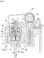
- the gas lighter has a lighter body 1 with a pocket portion 3 formed in the lighter body 1.
- the interior of the lighter body 1 around the outer surface of the pocket portion 3 serves as a fuel tank 5 where the flammable fuel is reserved.
- the flammable fuel in use is liquid petroleum gas which essentially consists of commercial butane and commercial propane (commercial butane: 90% and commercial propane: 10%).
- nozzle case 7 which has an almost cylindrical shape with an internal thread portion 7a formed on its outer surface.
- the pocket portion 3 is provided with an internal thread portion 3a, which engages with the internal thread portion 7a. With the internal thread portion 7a engaging with the internal thread portion 3a, the nozzle case 7 is secured to the pocket portion 3.
- a nozzle valve seat 9 isdisposed inside the nozzle case 7.
- a nozzle 11 is disposed through and inside the nozzle case 7, and is movable vertically in Fig. 1.
- a gas passage 11a and a gas intake hole 11b are formed in the center portion of the nozzle 11.
- a valve assembly (of, e.g., rubber) 13 is attached to the lower end of the nozzle 11. More specifically, the valve assembly 13 comprises a projection 13b protruding from the center portion of a disk 13a. The projection 13b is inserted into the gas passage lla of the nozzle 11 from the lower end.
- a valve seat 9a is formed at the center portion of the nozzle valve seat 9, with the valve assembly 13 seating on the valve seat 9a.
- the nozzle 11 and the valve assembly 13 are normally urged downward by a coil spring 15, so that the valve assembly 13 is seated on the valve seat 9a.
- an actuator 17 indicated by an imaginary line in FIG. 1 is rotated clockwise in FIG. 1 to shift the nozzle 11 upward against the force of the coil spring 15, the valve assembly 13 moves away from the valve seat 9a to allow the gas to flow in via the gas passage 9b of the nozzle valve seat 9, and the gas is thus ejected through the gas intake hole 11b and gas passage 11a of the nozzle 11.
- Fuel flow rate control means 19 is provided in the pocket portion 3 below the nozzle valve seat 9.
- This fuel flow rate control means 19 has a cylindrical elastic member 19a as a fuel impenetrable member, and a thread 19b inserted in the center portion of the elastic member 19a.
- the elastic member 19a is made of, for example, nitrile butadiene rubber (NBR) which has a strength of 70 degrees.
- NBR nitrile butadiene rubber
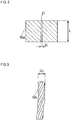
- the elastic member 19a has a length (L) of 2.5 mm in the axial direction. Bored in the axial center position of the elastic member 19a is a hole 21 in which the thread 19b is inserted.
- the boring of the hole 21 may be carried out by using a needle-like member, for example, and the diameter (D1) of the hole 21 is preferably slightly smaller than the outside diameter (D2) of the thread 19b to reduce the space between the thread 19b and diameter (D1), and thus any gas leak therethrough. It is not desirable that the hole diameter (D1) is larger than the outside diameter (D2).
- a crack may be formed.
- the thread 19b has a strand structure having a plurality of synthesized fibers like polyester fibers 22 (shown in Fig. 4) stranded.
- synthesized fibers for use in the present invention include vinylidene chloride, acrylic and nylon, for example.
- Each fiber 22 is a long fiber having a size of 1.3 deniers, and in the present embodiment there are 630 fibers 22 in thread 19a.
- the thread 19b with such a structure is inserted into the hole 21 of the elastic member 19a and is set as illustrated in Fig. 4.
- the gas flows through the clearances between the stranded fibers while its flow rate is regulated, as shown in Fig. 4.
- a flame from the apparatus of the present embodiment rose to a height of about 30 mm at the measured room temperature of 23°C.
- a wick 23 is placed below the fuel flow rate control means 19 so that the flammable fuel in the fuel tank 5 is sucked up through this wick 23 while its flow rate is regulated by the fuel flow rate control means 19 having the above-described structure.
- reference number “25” denotes a rotary file
- reference number “27” is a guide member located on either side of the rotary file
- reference numeral “29” is a flint.
- the fuel flow rate control means 19 has a certain thickness, unlike the conventional type which is a thin film type, so that this control means 19 is easier to handle at the time it is worked or the gas lighter is assembled. That is, as the elastic member 19a, the outer portion of the fuel flow rate control means 19, has a sufficient thickness as compared with the conventional thin film type, to allow the handling thereof.
- the elastic member 19a also improves the mechanical strength and the thermal strength of the fuel flow rate control means 19, allowing the control means 19 to perform a stable function over a long period of time. Further, the fuel flow rate control means 19 is less likely to be carelessly damaged at the time it is worked or the gas lighter is assembled or due to a change with time.
- the proper flow rate regulating characteristic can be obtained by altering the structure of the thread 19b (e.g., the type, the number and the length of the fibers, and the like) as needed. This contributes to eliminating a variation in the thread 19b, thus improving the stable combustibility.
- natural fibers are not used, also eliminating a variation in characteristic and ensuring highly accurate flow rate control.
- the thread 19b has a strand of polyester fibers as synthesized fibers in the first embodiment, vinylidene chloride hollow threads of synthesized fibers may be used as shown in FIG. 5.
- eight hollow threads 24 each consisting of long fibers of 50 deniers are stranded. In this case, it was confirmed through experiment that a flame therefrom rose to a height of about 30 mm at the measured room temperature of 23°C.
- the thread 19b consisting of the hollow threads 24 may be dipped in the fuel tank 5 so that the flammable fuel runs up through a hollow portion 24a of each hollow thread 24, thus regulating the gas flow rate. In this case, the thread 19b also serves as the wick 23 shown in FIG. 1.
- the thread 19b is constituted of synthesized fibers in the first and second embodiments
- the thread 19b is formed of carbon fibers in this embodiment. More specifically, about 100 fibers 22 each consisting of elongated fibers having a size of about 15 um (diameter of the fibers 22) were stranded. Accordingly, it was confirmed that a flame therefrom rose to a height of about 25 mm at the measured room temperature of 23°C.
- the thread 19b is formed of metal fibers (copper in this embodiment). More specifically, about 12 fibers each consisting of elongated fibers having a size of about 60 um were stranded. Accordingly, it was confirmed that a flame therefrom rose to a height of about 35 mm at the measured room temperature of 23°C.
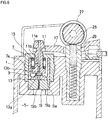
- FIG. 6 A fifth embodiment will now be explained with reference to FIG. 6.
- This embodiment has the structure of the first embodiment in FIG. 1 from which the wick 23 is eliminated.
- the wick 23 may not be necessary and may be omitted as shown in Fig. 6.
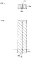
- the thread 19b is fitted in the through hole 21 of the elastic member 19a as a support, thus constituting the fuel flow rate control means 19.
- the support member 19a and the thread 19b are formed integrally in advance. More specifically, as shown in FIG. 8, thermal plastic resin, thermal hardening resin, rubber or the like may be extruded from an extrusion molding around the thread 19b (although not illustrated, an extrusion molding machine and predetermined molds are used at the time of extrusion molding), thus forming an article indicated by an imaginary lines in FIG. 8. This article is to be cut to the desired length to provide the fuel flow rate control means 19 ( Fig 7 and the solid linesin FIG.
- the fuel impenetrable member 19a need not be an elastic member.
- the member 19a should be an elastic member to keep the airtightness between the thread 19a and the fuel impenetrable member 19b.
- the thread 19b and the fuel impenetrable member 19b are formed integrally, no consideration need to be given to the air-tightness.
- the fuel impenetrable member 19b need not therefore be an elastic member. This structure can also produce the same advantages as described above.
- the thread 19b of the fuel flow rate control means 19 has a different structure.
- a single (or more) metal wire 31 is placed in the center portion, and fibers 33, selected from among synthesized fibers, regenerated fibers, metal fibers, carbon fibers and glass fibers, are placed around the metal wire 31.
- the thread 19b having this structure can have the same advantages as those above.
- the metal wire 31 is a soft copper wire plated with tin, for example, and has an outside diameter of 0.18 mm (180 ⁇ m) and has a length of 3.5 mm.
- This metal wire 31 imparts heat to the liquid gas that flows along this wire 31 and vaporizes the gas, thus ensuring efficient vaporization. That is, the latent heat the metal wire 31 has is given to the liquid gas.
- the thread 19b is a bundle of 1600 glass fibers. More specifically, 400 glass fibers of 6 ⁇ m are bundled and stranded, and four such strands are stranded in the opposite direction to the stranding direction of each strand.
- the fabrication process will be described step by step. First, 400 glass fibers of 6 um are made into a single bundle while being stranded. Four such bundles are then stranded around the metal wire 31 in the opposite direction to the stranding direction of each strand to be a single fiber bundle. The resultant bundle of fibers is placed in a feedable manner at the center of the nozzle of the extrusion molding machine, molten polyethylene is supplied, and all are integrated by the extrusion molding machine.
- the passage where the liquid fuel passes runs mainly through the clearances between the thread 19b and the metal wire 31, and the clearances in the thread 19b itself (clearances between the individual glass fibers) can also serve as a gas passage, though slightly.
- a polyethylene resin comes between the thread 19b and the support member 19a at the time of extrusion molding, shielding the clearances so that only a few clearances serve as the passage.
- the clearances between the thread 19b and the metal wire 31 are allowed to serve as the main passage because the heat to vaporize the liquid gas can efficiently be applied to the gas traveling along the metal wire 31.
- FIG. 10 An eighth embodiment of this invention will now be explained with reference to FIG. 10.
- the structure of the thread 19b of the fuel flow rate control means 19 is also modified.
- a single (or more) metal wire 31 is placed in the center portion, and hollow threads 33 are placed around this metal wire 31.
- the thread 19b having this structure can have the same advantages as those discussed above.
- a ninth embodiment of this invention will now be explained with reference to FIG. 11.
- This embodiment is designed to be able to adjust the flame height as needed.
- An internal thread portion 7a is provided at the outer surface portion of the nozzle case 7, and an internal thread portion 3a is formed on the pocket portion 3 of the lighter body 1.
- the nozzle case 7 is attached to the pocket portion 3 by the engagement of the internal thread portion 7a with the internal thread portion 3a.
- the structure up to this point is the same as that of the first embodiment (shown in FIG. 1).
- a rotary actuator 41 is attached to the top end of the nozzle case 7. As the user turns this rotary actuator 41 with the thumb, for example, in the proper direction, the nozzle case 7 rotates, so that the nozzle case 7 and nozzle valve seat 9 can be lifted up.
- a porous member 43 is provided between the nozzle valve seat 9 and the fuel flow rate control means 19. This porous member 43 may be formed of urethane foam.
- the user when one wants to increases the flame height, the user should turn the rotary actuator 41 in one direction.
- This moves the nozzle case 7 up, increasing the space between the nozzle valve seat 9 and the fuel flow rate control means 19.
- the porous member 43 therefore expands accordingly, and the bubble density in the porous member 43 is thus increased. Therefore, the amount of the fuel passing therethrough increases and the flame height rises eventually.
- the user should turn the rotary actuator 41 in the other direction. This moves the nozzle case 7 downward, narrowing the space between the nozzle valve seat 9 and the fuel flow rate control means 19.
- the porous member 43 is compressed accordingly, reducing the bubble density in the porous member 43. Therefore, the amount of the fuel passing therethrough decreases, lowering the flame height.
- the provision of the porous member 43 can change the flow rate of the flammable fuel. By setting the height of the porous member 43 to a predetermined amount, therefore, the flame height can be restricted to a given height. Further, the porous member 43 when properly expanded or compressed can adjust the flame height to the desired level.
- the present invention is not limited to the above-described embodiments.
- a gas lighter has been explained as a combustion apparatus for flammable fuel in the foregoing description of those embodiments, this invention can applied to various types of ignition devices beside the gas lighter, a portable hot plate, a lamp, etc.
- the fibers constituting the thread 19b of the fuel flow rate control means 19 may be surface-treated glass fibers or the like beside the aforementioned types, regenerated fibers, carbon fibers or glass fibers whose surfaces are plated with gold. Any two types of fibers among the synthesized fibers, metal fibers, carbon fibers and glass fibers may be combined. Alternatively, ordinary fibers may be combined with a hollow thread.
- the thread has a strand structure in the above-described embodiments, the thread is not limited to this particular type, but may be formed by bundling raw threads.
- the specific values given in the description of the individual embodiments are to be considered as just illustrative and not restrictive.
Landscapes
- Engineering & Computer Science (AREA)
- Chemical & Material Sciences (AREA)
- Combustion & Propulsion (AREA)
- Mechanical Engineering (AREA)
- General Engineering & Computer Science (AREA)
- Lighters Containing Fuel (AREA)
Applications Claiming Priority (6)
| Application Number | Priority Date | Filing Date | Title |
|---|---|---|---|
| JP226515/93 | 1993-08-19 | ||
| JP22651593 | 1993-08-19 | ||
| JP287556/93 | 1993-10-22 | ||
| JP28755693 | 1993-10-22 | ||
| JP6079957A JPH07167431A (ja) | 1993-08-19 | 1994-03-24 | 燃焼装置 |
| JP79957/94 | 1994-03-24 |
Publications (2)
| Publication Number | Publication Date |
|---|---|
| EP0640795A2 true EP0640795A2 (de) | 1995-03-01 |
| EP0640795A3 EP0640795A3 (de) | 1995-11-29 |
Family
ID=27303148
Family Applications (1)
| Application Number | Title | Priority Date | Filing Date |
|---|---|---|---|
| EP94306105A Withdrawn EP0640795A3 (de) | 1993-08-19 | 1994-08-18 | Verbrennungsvorrichtung. |
Country Status (6)
| Country | Link |
|---|---|
| EP (1) | EP0640795A3 (de) |
| JP (1) | JPH07167431A (de) |
| KR (1) | KR950006310A (de) |
| AU (1) | AU7037594A (de) |
| BR (1) | BR9402771A (de) |
| CA (1) | CA2130371A1 (de) |
Cited By (1)
| Publication number | Priority date | Publication date | Assignee | Title |
|---|---|---|---|---|
| EP1484556A1 (de) * | 2001-12-05 | 2004-12-08 | The Japan Smoking Articles Corporate Association | Methode und Verfahren für die Regelung des Durchflusses von gasförmigem Kohlenwasserstoff |
Families Citing this family (3)
| Publication number | Priority date | Publication date | Assignee | Title |
|---|---|---|---|---|
| JPH11223339A (ja) * | 1998-02-06 | 1999-08-17 | Tokai:Kk | 液体燃料燃焼器具の燃料保持部材 |
| KR200275113Y1 (ko) * | 1999-06-21 | 2002-05-10 | 배한성 | 담배형 라이터 |
| CN113154469B (zh) * | 2021-05-21 | 2023-04-14 | 中山市金艺金属制品有限公司 | 一种嵌入于燃气灶内部的双联动阀门控火开关 |
Family Cites Families (4)
| Publication number | Priority date | Publication date | Assignee | Title |
|---|---|---|---|---|
| FR1343832A (fr) * | 1962-06-19 | 1963-11-22 | Samao S A | Soupape pour briquet à gaz |
| FR2044258A5 (de) * | 1969-05-28 | 1971-02-19 | Grudzinski Richard | |
| FR2371633A1 (fr) * | 1976-11-19 | 1978-06-16 | Dupont S T | Appareil a gaz liquefie, notamment briquet a gaz pour fumeurs |
| ES2005639A6 (es) * | 1987-10-15 | 1989-03-16 | Sandaco Sa | Encendedor de gas licuado. |
-
1994
- 1994-03-24 JP JP6079957A patent/JPH07167431A/ja active Pending
- 1994-08-18 EP EP94306105A patent/EP0640795A3/de not_active Withdrawn
- 1994-08-18 CA CA002130371A patent/CA2130371A1/en not_active Abandoned
- 1994-08-19 BR BR9402771A patent/BR9402771A/pt not_active Application Discontinuation
- 1994-08-19 AU AU70375/94A patent/AU7037594A/en not_active Abandoned
- 1994-08-19 KR KR1019940020486A patent/KR950006310A/ko not_active Withdrawn
Cited By (1)
| Publication number | Priority date | Publication date | Assignee | Title |
|---|---|---|---|---|
| EP1484556A1 (de) * | 2001-12-05 | 2004-12-08 | The Japan Smoking Articles Corporate Association | Methode und Verfahren für die Regelung des Durchflusses von gasförmigem Kohlenwasserstoff |
Also Published As
| Publication number | Publication date |
|---|---|
| JPH07167431A (ja) | 1995-07-04 |
| EP0640795A3 (de) | 1995-11-29 |
| CA2130371A1 (en) | 1995-02-20 |
| KR950006310A (ko) | 1995-03-20 |
| AU7037594A (en) | 1995-03-02 |
| BR9402771A (pt) | 1995-04-04 |
Similar Documents
| Publication | Publication Date | Title |
|---|---|---|
| EP0074956B1 (de) | Mit flüssiggas betriebenes feuerzeug, insbesondere taschenfeuerzeug | |
| KR930020076A (ko) | 산소-연료 연소 장치 | |
| EP0065537A1 (de) | Mit flüssiggas betriebenes feuerzeug. | |
| EP0640795A2 (de) | Verbrennungsvorrichtung | |
| US4859174A (en) | Device for igniting combustible materials | |
| US4680007A (en) | Lighter with adjustable flame | |
| KR920001121A (ko) | 가스라이터와 유사한 기구용 유동률 조절장치와 그 안에 사용하기 위한 미공성 중합체 필터를 제조하는 방법 | |
| CA1122808A (en) | Flame-limiting device for a gas lighter | |
| US5584681A (en) | Gas lighter | |
| US4522582A (en) | Fuel control system for burners | |
| US20050175947A1 (en) | Filter structure of igniter | |
| US20020055075A1 (en) | Lantern with improved choke and regulator | |
| KR20000068305A (ko) | 액체 연료용 연소 기구에 있어서의 연소심 | |
| EP0942233B1 (de) | Struktur einer verbrennungskammer für anzünder | |
| US2964288A (en) | Valves | |
| US3533721A (en) | Burner valve for gas-fueled pipe and cigarette lighters | |
| JPS58145823A (ja) | ガスライタ | |
| US4419069A (en) | Flame igniter | |
| CN1101409A (zh) | 燃烧装置 | |
| JPS6143054Y2 (de) | ||
| JPS6244170B2 (de) | ||
| CA1314401C (en) | Liquefied gas lighter | |
| JPH06117635A (ja) | 液化燃料の流量・圧力調整装置 | |
| US1273281A (en) | Soldering-tool. | |
| US700893A (en) | Gas-check for bunsen or similar burners. |
Legal Events
| Date | Code | Title | Description |
|---|---|---|---|
| PUAI | Public reference made under article 153(3) epc to a published international application that has entered the european phase |
Free format text: ORIGINAL CODE: 0009012 |
|
| AK | Designated contracting states |
Kind code of ref document: A2 Designated state(s): AT BE CH DE DK ES FR GB GR IE IT LI NL PT SE |
|
| PUAL | Search report despatched |
Free format text: ORIGINAL CODE: 0009013 |
|
| AK | Designated contracting states |
Kind code of ref document: A3 Designated state(s): AT BE CH DE DK ES FR GB GR IE IT LI NL PT SE |
|
| STAA | Information on the status of an ep patent application or granted ep patent |
Free format text: STATUS: THE APPLICATION IS DEEMED TO BE WITHDRAWN |
|
| 18D | Application deemed to be withdrawn |
Effective date: 19960530 |