EP0640272B2 - Bodenbearbeitungskombination - Google Patents
Bodenbearbeitungskombination Download PDFInfo
- Publication number
- EP0640272B2 EP0640272B2 EP94109343A EP94109343A EP0640272B2 EP 0640272 B2 EP0640272 B2 EP 0640272B2 EP 94109343 A EP94109343 A EP 94109343A EP 94109343 A EP94109343 A EP 94109343A EP 0640272 B2 EP0640272 B2 EP 0640272B2
- Authority
- EP
- European Patent Office
- Prior art keywords
- soil
- cultivation
- combination according
- frame
- coupling
- Prior art date
- Legal status (The legal status is an assumption and is not a legal conclusion. Google has not performed a legal analysis and makes no representation as to the accuracy of the status listed.)
- Expired - Lifetime
Links
- 239000002689 soil Substances 0.000 title description 10
- 230000008878 coupling Effects 0.000 claims description 30
- 238000010168 coupling process Methods 0.000 claims description 30
- 238000005859 coupling reaction Methods 0.000 claims description 30
- 238000010899 nucleation Methods 0.000 claims 1
- 238000003971 tillage Methods 0.000 description 39
- 241000196324 Embryophyta Species 0.000 description 2
- 241001236644 Lavinia Species 0.000 description 2
- 238000009331 sowing Methods 0.000 description 2
- 240000001931 Ludwigia octovalvis Species 0.000 description 1
- 230000006978 adaptation Effects 0.000 description 1
- 238000009412 basement excavation Methods 0.000 description 1
- 239000000969 carrier Substances 0.000 description 1
- 230000006835 compression Effects 0.000 description 1
- 238000007906 compression Methods 0.000 description 1
- 238000010276 construction Methods 0.000 description 1
- 238000004519 manufacturing process Methods 0.000 description 1
- 238000003860 storage Methods 0.000 description 1
Images


Classifications
-
- A—HUMAN NECESSITIES
- A01—AGRICULTURE; FORESTRY; ANIMAL HUSBANDRY; HUNTING; TRAPPING; FISHING
- A01B—SOIL WORKING IN AGRICULTURE OR FORESTRY; PARTS, DETAILS, OR ACCESSORIES OF AGRICULTURAL MACHINES OR IMPLEMENTS, IN GENERAL
- A01B49/00—Combined machines
- A01B49/04—Combinations of soil-working tools with non-soil-working tools, e.g. planting tools
- A01B49/06—Combinations of soil-working tools with non-soil-working tools, e.g. planting tools for sowing or fertilising
Definitions
- the invention relates to a tillage combination with at least two in the working direction on each other following tillage equipment, from the first directly to a tractor is connectable.
- Such a harrow is for example from the German utility model 91 14 455 become known.
- a first tillage machine used with a tine rotor.
- this additional frame is a Additional frame connected to a seeder is, with this additional frame each two different Connection points for the connection of a Having downstream Krümlerwalze, wherein these Crumbler then depending on the selected connection points is arranged in front of or behind the coulters.
- the front Replacing the implement that this example can also be replaced by a rotary harrow.
- Tillage combinations are drawn off at least two, but often more in a row switched devices exist, so that the tillage be done in one operation can (see, for example, DE-A-3205200).
- a device combination is generally a leading, not too deep working device required that a Krümel raised and compression means follows, then it it is advantageous that then immediately sowing he follows.
- tillage combinations it has turned out that a once chosen combination is not for everyone Processing conditions are equally well suited, but that here too different requirements different tillage combinations require.
- the object of the present invention is a tillage combination of the beginning mentioned type so that they with a only a small effort to meet the manifold requirements customizable with conventional devices, easy in theirs Construction and thus inexpensive to manufacture, has a comparatively small length and thus has an overall focus, by far ahead of the Support wheels lies and with the one in a single operation Field order is feasible.
- the additional frame with the frame of the front lying in the direction of travel harrow detachable via a flange connection connected, so that the replacement of this tillage machine either completely or through Exchange of individual tools or tool groups the same can be made.
- the Additional frame itself is provided with training wheels, the allow the additional framework and thus the preceding one Soil cultivation device as well as the others Tillage equipment connected to the additional frame dig.
- the additional framework as such carries two coupling rods, which are advantageous in shape are formed by upper and lower links, so that on this additional frame commercial tillage equipment can be connected, for example a crumb roller as well as a Seeder.
- the respective front coupling linkage of the additional frame is with its upper link attached to a tower attached to a crossbeam of the Additional frame is arranged.
- the top link of the in Driving direction behind coupling linkage is on a bridge attached, which is arranged on the longitudinal beams is.
- This has the advantage that thereby a relatively large space for the front in the direction of travel lying upper link is created.
- the lower link of the front Coupling linkage laterally or below the Side members of the additional frame are arranged. hereby it is possible to put the front linkage in near the front end of the additional frame arrange so that the length of the entire Tillage combination comparatively short can be held, which also causes the Focus of the entire tillage combination essentially in front of the support wheels of the additional frame lies.
- the lower link both the front and the front the rear coupling linkage are in their pivoting movement down through adjustable Limited stops. Furthermore, these are Lower link advantageous by means of springs relative to the Supported additional frame, so that for the lower links worn other tillage equipment a good soil adaptation is obtained and the Tool groups (eg the crumb roller) by Shares of the frame weight can be charged.
- Tool groups eg the crumb roller
- Another advantageous measure of the invention is that the lower link of the rear Coupling linkage springy on the frame supported the leading tillage equipment are. This can be in a simple way a additional load on the preceding tillage equipment, for example, a crumb roller by a downstream, for example seed drill reach, whereby the Bodenanpreßdruck the Bottom roller is adjustable.
- each behind lying coupling linkage on a own excavating device has, whereby the expiration the lifting operations at the field end optimized and what with appropriate design of the linkage in particular is advantageous for road transport, because As a result, the transport length of the entire tillage combination can be reduced.
- a front Soil cultivation device a disc harrow, a spade harrow, a cultivator or a combination of the aforementioned Devices is selected.
- subordinate Soil cultivation device offers a roller, in particular a crumb roller, wherein the third Soil cultivation device advantageous a seeder is. Such a combination allows tillage and sowing without any preparatory work in one operation.
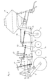
- the tillage combination shown in Figs. 1 to 3 consists of three soil tillage implements 2, 3, 4, wherein the first harrow 2 has its own frame 5, while the tillage equipment 3, 4 a Divide frame 6.
- On the frame 5 of the front Tillage device 2 are folding side frames 7 arranged in the embodiment disc harrows 9 wear.
- a Tiller 10 hinged which via a turnbuckle 11 (in Fig. 2 not shown) relative to the frame 5 adjustable is.
- a turnbuckle 11 in Fig. 2 not shown
- the drawbar 10 At the front end of the drawbar 10 are Unterienkeran everything 12, 13 for connection to a not shown tractor.
- the height adjustment of the support wheels 14, 15 relative to Züsatzrahmen 6 via hydraulic cylinder 18, which in Fig. 2 has been omitted for clarity are.
- the carrier 16, 17 of the support wheels 14, 15 engage their ends rigidly connected to the frame 6 Arms 19, at one end and the hydraulic cylinder 18 are articulated.
- the other ends of the Hydraulic cylinders 18 engage the carriers 16, 17.
- the relative to the additional frame 6 and thus also to Frame 5 height adjustable support wheels 14, 15 serve on the one hand for lifting the device and can on the other hand used to regulate the working depth become.
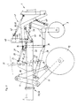
- the additional frame 6 consists of two longitudinal members 21, 22, which are centrally connected by a cross member 23 are (Fig. 3). On the cross member 23 is a tower 24th arranged, the connections 25 for the upper link 26th a front coupling linkage 27 carries, whose associated lower link 28 hinged to a tab 29 is, in turn, below the longitudinal beams 21, 22nd the additional frame 6 is attached.
- Threaded rod 31 stored, the lower end by a rod connecting the lower links 28 32nd engages, so that thereby a movement of the lower link 28 adjustable limit stop limiting downwards is created.
- the Lower link 28 supported by a spring element 33, so that they are upwards relative to the frame are movably arranged.
- the spring force is over one Threaded nut 30 adjustable.
- the harrow 3 consists of a crumbler roller, which in turn has a frame 34, with connections 35, 36 for the upper and Lower link 26, 28 of the front coupling linkage 27th are provided.
- the additional frame 6 further has an im Area of its rear end lying connection points 37, 38 for the lower links 39, 40 of the rear Coupling rod 41 on.
- the top link 42 of the coupling rod 41 is at a portal-like bridge 43rd attached to the longitudinal members 21, 22 with their side panels 44 is attached. In these side parts are Hole rows 45 provided in the pins inserted are those that limit the path of the lower link 39, 40 serve down. Furthermore, attack the Lower links excavators 46, with which the attached to the coupling rod 41 tillage device 4 is lifted.
- FIG. 4 In the embodiment of FIG. 4 is the same additional frame 6 with the coupling rods 27 and 41, but here was the combination chosen differently and that was before the tillage implement 3, d. H. the crumb roller one Messerrollegge 51 turned on, turn turn Connection points 52, 53, to which the Tillage device 3 is connected.
- the Seeder 4 is immediate in the embodiment on the frame 34 of the tillage tool 3 connected. The same applies to their top link.
- the connection of the rear seed drill However, also with the upper link 54 directly to the bridge 43 of the additional frame 6, wherein on the other hand also lower link 39, 40 accordingly
- the embodiment of FIG. 3 are provided can to connect the drill. Both Connection types are possible, what the great variability the tillage combination according to the invention shows.
- the front harrow 2 can advantageous still provided with their own support wheels 60, 61 so that this in the case of dismantling easy to roll away, so that thereby the exchange the device is further simplified.
- the additional frame 6 is upper a flange connection 55, 56 on the frame 5 of the front cultivator 2 connected.
Landscapes
- Life Sciences & Earth Sciences (AREA)
- Engineering & Computer Science (AREA)
- Mechanical Engineering (AREA)
- Soil Sciences (AREA)
- Environmental Sciences (AREA)
- Agricultural Machines (AREA)
- Soil Working Implements (AREA)
- Transplanting Machines (AREA)
- Superconductors And Manufacturing Methods Therefor (AREA)
Description
- Fig. 1
- eine Seitenansicht eines Ausführungsbeispieles einer erfindungsgemäßen Bodenbearbeitungskombination.
- Fig. 2
- eine Draufsicht auf das Ausführungsbeispiel nach Fig. 1,
- Fig. 3
- einen Ausschnitt aus der Seitenansicht gemäß Fig. 1 in vergrößertem Maßstab,
- Fig. 4
- eine Seitenansicht entsprechend Fig. 3, jedoch mit einer anderen Gerätekombination,
- Fig. 5
- eine Draufsicht auf ein vorderes Bodenbearbeitungsgerät, wobei hier zwei alternative Geräte in einer Darstellung gezeigt sind und
- Fig. 6
- eine Seitenansicht gemäß Fig. 5.
- 1
- Bodenbearbeitungskombination
- 2
- Bodenbearbeitungsgerät
- 3
- Bodenbearbeitungsgerät
- 4
- Bodenbearbeitungsgerät
- 5
- Rahmen
- 6
- Zusatzrahmen
- 7
- Seitenrahmen
- 8
- Seitenrahmen
- 9
- Scheibeneggen
- 10
- Deichsel
- 11
- Spannschloss
- 12
- Unterlenkeranschlüsse
- 13
- Unterlenkeranschlüsse
- 14
- Stützräder
- 15
- Stützräder
- 16
- Träger
- 17
- Träger
- 18
- Hydraulikzylinder
- 19
- Arm
- 20 21
- Längsträger
- 22
- Längsträger
- 23
- Querträger
- 24
- Turm
- 25
- Anschluß
- 26
- Oberlenker
- 27
- Koppelgestänge
- 28
- Unterlenker
- 29
- Lasche
- 30
- Gewindemutter
- 31
- Gewindestange
- 32
- Stange
- 33
- Federelement
- 34
- Rahmen
- 35
- Anschluß
- 36
- Anschluß
- 37
- Anschlußpunkt
- 38
- Anschlußpunkt
- 39
- Unterlenker
- 40
- Unterlenker
- 41
- Koppelgestänge
- 42
- Oberlenker
- 43
- Brücke
- 44
- Seitenteile
- 45
- Lochreihen
- 46
- Aushubvorrichtungen
- 47
- Säkasten
- 48
- Säschare
- 49
- Federelement
- 50
- Federelement
- 51
- Messerrollegge
- 52
- Anschlußpunkt
- 53
- Anschlußpunkt
- 54
- Oberlenker
- 55
- Flanschverbindung
- 56
- Flanschverbindung
- 57
- Werkzeug
- 58
- Werkzeug
- 59
- Werkzeug
- 60
- Stützräder
- 61
- Stützräder
Claims (16)
- Bodenbearbeitungskombination (1) mit mindestens zwei in Arbeitsrichtung aufeinander folgenden Bodenbearbeitungsgeräten (2, 3, 4), von denen das erste (2) unmittelbar an eine Zugmaschine anschließbar ist,
dadurch gekennzeichnet, dass am Rahmen (5) des ersten Bodenbearbeitungsgerätes (2) ein Zusatzrahmen (6) starr angeordnet ist, der von am Zusatzrahmen (6) befestigten und zu diesen höhenverstellbaren Stützrädern zumindest bei der Arbeit getragen ist,
dass am Zusatzrahmen (6) mindestens zwei in Fahrtrichtung hintereinander angeordnete Koppelgestänge (27, 41) für den Anschluss weiterer Bodenbearbeitungsgeräte (3, 4) vorgesehen sind und
dass die Koppelgestänge (27, 41) höhenverschwenkbar relativ zum Zusatzrahmen (6) angeordnet sind, wobei der Schwenkweg nach unten durch einstellbare Anschläge begrenzt ist. - Bodenbearbeitungskombination nach Anspruch 1, dadurch gekennzeichnet, daß der Zusatzrahmen (6) an seinem hinteren Ende U-förmig ausgebildet ist und daß die Koppelgestänge (27, 41) einerseits an den Enden der Längsträger (21, 22) und andererseits an, die Längsträger (21, 22) verbindenden Querträgern (23) des Zusatzrahmens (6) angeordnet sind.
- Bodenbearbeitungskombination nach Anspruch 1 oder 2, dadurch gekennzeichnet, daß die Koppelgestänge (27, 41) in Form von Ober-und Unterlenkern (26, 28; 39, 40, 42) ausgebildet sind.
- Bodenbearbeitungskombination nach einem der Ansprüche 1 bis 3, dadurch gekennzeichnet, daß der Oberlenker (26) des in Fahrtrichtung vorn liegenden Koppelgestänges (27) an einem mit einem Querträger (23) verbundenen Turm (24) und der Oberlenker (42) des hinten liegenden Koppelgestänges (41) an einer die Enden der Längsträger (21, 22) übergreifenden Brücke (43) angeordnet ist.
- Bodenbearbeitungskombination nach einem der Ansprüche 1 bis 4, dadurch gekennzeichnet, daß die vorderen und/oder hinteren Unterlenker (28, 39, 40) der Koppelgestänge (27, 41) federnd gegenüber dem Zusatzrahmen (6) abgestützt sind.
- Bodenbearbeitungskombination nach einem der Ansprüche 1 bis 5, dadurch gekennzeichnet, daß die Unterlenker der hinteren Koppelgestänge (41) jeweils federnd gegenüber dem Rahmen des vorauslaufenden Bodenbearbeitungsgerätes (3) abgestützt sind.
- Bodenbearbeitungskombination nach einem der Ansprüche 1 bis 6, dadurch gekennzeichnet, daß zumindest die hinten liegenden Koppelgestänge (41) eine eigene Aushubvorrichtung (46) haben.
- Bodenbearbeitungskombination nach einem der Ansprüche 1 bis 7, dadurch gekennzeichnet, daß der Zusatzrahmen (6) mit dem Rahmen (5) des ersten Bodenbearbeitungsgerätes (2) lösbar verbunden ist.
- Bodenbearbeitungskombination nach Anspruch 8, dadurch gekennzeichnet, daß der Zusatzrahmen (6) über eine Flanschverbindung (55, 56) mit dem Rahmen (5) des ersten Bodenbearbeitungsgerätes (2) verbunden ist.
- Bodenbearbeitungskombination nach einem der Ansprüche 1 bis 9, dadurch gekennzeichnet, daß das vordere Bodenbearbeitungsgerät (2) eine Scheibenegge, eine Spatenrollegge, ein Grubber oder eine Kombination vorgenannter Geräte ist.
- Bodenbearbeitungskombination nach einem der Anspruche 1 bis 9, dadurch gekennzeichnet, daß an dem ersten Koppelgestänge (27) eine Walze insbesondere eine Krümelwalze angeschlossen ist.
- Bodenbearbeitungskombination nach Anspruch 11, dadurch gekennzeichnet, daß zwischen dem ersten Koppelgestänge (27) und der Walze (3) eine zweireihige Messerrollegge (51) angeordnet ist.
- Bodenbearbeitungskombination nach Anspruch 12, dadurch gekennzeichnet, daß sowohl die Messerrollegge (51) wie auch die Walze (3) gegenüber ihrem Koppelgestänge (27) federnd abgestützt sind.
- Bodenbearbeitungskombination nach einem der Ansprüche 1 bis 13, dadurch gekennzeichnet, daß an dem zweiten Koppelgestänge (41) eine Sämaschine (4) angeschlossen ist
- Bodenbearbeitungskombination nach einem der Ansprüche 1 bis 14, dadurch gekennzeichnet, daß das erste Bodenbearbeitungsgerät (2) von der Zugmaschine getragen ist.
- Bodenbearbeitungskombination nach einem der Ansprüche 1 bis 15, dadurch gekennzeichnet, daß die Stützräder (14, 15) unmittelbar vor oder zwischen den Koppelgestängen (27, 41) angeordnet sind.
Applications Claiming Priority (2)
| Application Number | Priority Date | Filing Date | Title |
|---|---|---|---|
| DE9312364U DE9312364U1 (de) | 1993-08-25 | 1993-08-25 | Bodenbearbeitungskombination |
| DE9312364U | 1993-08-25 |
Publications (3)
| Publication Number | Publication Date |
|---|---|
| EP0640272A1 EP0640272A1 (de) | 1995-03-01 |
| EP0640272B1 EP0640272B1 (de) | 1999-04-14 |
| EP0640272B2 true EP0640272B2 (de) | 2005-02-02 |
Family
ID=6896929
Family Applications (1)
| Application Number | Title | Priority Date | Filing Date |
|---|---|---|---|
| EP94109343A Expired - Lifetime EP0640272B2 (de) | 1993-08-25 | 1994-06-17 | Bodenbearbeitungskombination |
Country Status (2)
| Country | Link |
|---|---|
| EP (1) | EP0640272B2 (de) |
| DE (2) | DE9312364U1 (de) |
Cited By (1)
| Publication number | Priority date | Publication date | Assignee | Title |
|---|---|---|---|---|
| DE102011102529A1 (de) | 2010-06-11 | 2012-02-16 | Rabe Agri Gmbh | Bodenbearbeitungskombination |
Families Citing this family (6)
| Publication number | Priority date | Publication date | Assignee | Title |
|---|---|---|---|---|
| DE19529540A1 (de) * | 1995-08-11 | 1996-05-15 | Karl Bohner | Aufsattelmaschine |
| DE19541656A1 (de) * | 1995-11-08 | 1997-05-15 | Fritz Guettler | Bodenwalze mit Rahmen für den wechselweisen Anbau a) an die Heck-Hebeeinrichtung eines Schleppers, b) an die Fronthebeeinrichtung, c) an ein eigenes Fahrwerk mit Zugdeichsel |
| FR2769460B1 (fr) * | 1997-10-15 | 1999-12-10 | Soc D Etablissements Louis Qui | Machine a travailler et ensemencer la terre en une seule passe |
| DE19803199A1 (de) * | 1997-12-19 | 1999-08-26 | Amazonen Werke Dreyer H | Landwirtschaftliche Bestellkombination |
| GB2350996B (en) * | 1999-06-12 | 2003-08-20 | Chris Green | Agricultural machine |
| DE102017204890A1 (de) | 2017-03-23 | 2018-09-27 | Hermann Dreesbeimdieke | Bodenbearbeitungsgerät |
Family Cites Families (11)
| Publication number | Priority date | Publication date | Assignee | Title |
|---|---|---|---|---|
| US190366A (en) * | 1877-05-01 | Improvement in car-springs | ||
| US3576213A (en) * | 1969-03-12 | 1971-04-27 | David B Hall | Farm implement |
| US3701327A (en) * | 1970-06-01 | 1972-10-31 | Allis Chalmers Mfg Co | Planter and method of preparing soil |
| NL7416324A (nl) * | 1974-12-16 | 1976-06-18 | Lely Nv C Van Der | Grondbewerkingsmachine. |
| DE2528930A1 (de) * | 1975-06-28 | 1977-01-13 | Amazonen Werke Dreyer H | Tragrahmen fuer landwirtschaftliche maschinen und geraete |
| DE7615202U1 (de) * | 1976-05-13 | 1977-02-24 | Maschinenfabrik Rau Ohg, 7315 Weilheim | An einen schlepper ankuppelbare, fahrbare tragvorrichtung fuer an diese anzuhaengende landwirtschafltiche, der bodenbearbeitung dienende arbeitsgeraete |
| DE2754871A1 (de) * | 1977-12-09 | 1979-06-13 | Niemeyer Gmbh & Co Kg Soehne | Landwirtschaftliche geraetekombination |
| DE3205200A1 (de) * | 1982-02-13 | 1983-08-25 | Ernst 7326 Heiningen Weichel | Nachlaufgeraetetraeger fuer schlepper und arbeitsmaschinen |
| US4539921A (en) * | 1983-12-16 | 1985-09-10 | Haybuster Manufacturing, Inc. | Drill frame construction |
| DE9002700U1 (de) * | 1990-03-08 | 1990-05-10 | Rabewerk GmbH + Co, 4515 Bad Essen | Bodenbearbeitungsgerät |
| FR2701803B1 (fr) * | 1993-02-25 | 1995-04-21 | Huard Sa | Semoir perfectionné. |
-
1993
- 1993-08-25 DE DE9312364U patent/DE9312364U1/de not_active Expired - Lifetime
-
1994
- 1994-06-17 EP EP94109343A patent/EP0640272B2/de not_active Expired - Lifetime
- 1994-06-17 DE DE59408106T patent/DE59408106D1/de not_active Expired - Fee Related
Cited By (1)
| Publication number | Priority date | Publication date | Assignee | Title |
|---|---|---|---|---|
| DE102011102529A1 (de) | 2010-06-11 | 2012-02-16 | Rabe Agri Gmbh | Bodenbearbeitungskombination |
Also Published As
| Publication number | Publication date |
|---|---|
| EP0640272A1 (de) | 1995-03-01 |
| EP0640272B1 (de) | 1999-04-14 |
| DE59408106D1 (de) | 1999-05-20 |
| DE9312364U1 (de) | 1993-10-28 |
Similar Documents
| Publication | Publication Date | Title |
|---|---|---|
| DE102022113040B3 (de) | Bodenbearbeitungsgerät | |
| EP4265086A1 (de) | Bodenbearbeitungsgerät | |
| DE2616545A1 (de) | Wurzel- und stengelshredder | |
| EP3545737B1 (de) | Bodenbearbeitungsgerät mit wenigstens einer striegelwalzeneinheit | |
| DE102021107169B4 (de) | Bodenbearbeitungsgerät | |
| EP0453852A1 (de) | Bodenbearbeitungsmaschinensystem | |
| DE102021102507B4 (de) | Bodenbearbeitungsgerät | |
| DE69325166T2 (de) | Kombination eines drehpfluges und eines gerätes zur saatbettbereitung | |
| EP3782443B1 (de) | Landwirtschaftliche bodenbearbeitungsmaschine zur bearbeitung von reihenkulturen | |
| EP0047852B1 (de) | Verfahren und Gerätekombination zur Bodenlockerung, zur Verbesserung der Krümelstruktur und zur Unkrautbekämpfung | |
| EP0640272B1 (de) | Bodenbearbeitungskombination | |
| DE2515767A1 (de) | Saatbeetaufbereitungsgeraet | |
| EP2835043B1 (de) | Gezogene landwirtschaftliche Bestellkombination und Verfahren zum Überführen einer landwirtschaftlichen Bestellkombination aus einer Transportposition in eine Arbeitsposition und umgekehrt | |
| DD235992A5 (de) | Arbeitsverfahren zur aufbereitung als ackerbodens sowie eine geraetekombination zur durchfuehrung des verfahrens | |
| DE102020133571A1 (de) | Bodenbearbeitungsgerät | |
| DE3033144C2 (de) | Schleppergezogene Bodenbearbeitungs- und Sämaschine | |
| DE102023103058A1 (de) | Bodenbearbeitungsgerät | |
| DE60314193T2 (de) | Sämaschine | |
| DE3229232A1 (de) | Zapfwellengetriebenes arbeitsgeraet zur bodenlockerung, kruemelung und zum einmischen von ernterueckstaenden | |
| DE102017115929A1 (de) | Gezogenes landwirtschaftliches Arbeitsgerät mit kraftbetriebenen Bodenbearbeitungs- und/oder Säelementen | |
| AT399080B (de) | Gerät zum vorbereiten des bodens für die reihensaat | |
| DE3127263A1 (de) | "geraet zur bodenlockerung" | |
| EP0471156B1 (de) | Kombinationsgerät zur Bodenbearbeitung | |
| DE69303396T2 (de) | Landwirtschaftliche Gerätekombination von einer Egge mit einer Sämaschine | |
| DE202023106519U1 (de) | Bodenbearbeitungsgerät |
Legal Events
| Date | Code | Title | Description |
|---|---|---|---|
| PUAI | Public reference made under article 153(3) epc to a published international application that has entered the european phase |
Free format text: ORIGINAL CODE: 0009012 |
|
| AK | Designated contracting states |
Kind code of ref document: A1 Designated state(s): DE FR GB |
|
| 17P | Request for examination filed |
Effective date: 19950309 |
|
| 17Q | First examination report despatched |
Effective date: 19951204 |
|
| GRAG | Despatch of communication of intention to grant |
Free format text: ORIGINAL CODE: EPIDOS AGRA |
|
| GRAG | Despatch of communication of intention to grant |
Free format text: ORIGINAL CODE: EPIDOS AGRA |
|
| GRAH | Despatch of communication of intention to grant a patent |
Free format text: ORIGINAL CODE: EPIDOS IGRA |
|
| GRAH | Despatch of communication of intention to grant a patent |
Free format text: ORIGINAL CODE: EPIDOS IGRA |
|
| GRAA | (expected) grant |
Free format text: ORIGINAL CODE: 0009210 |
|
| AK | Designated contracting states |
Kind code of ref document: B1 Designated state(s): DE FR GB |
|
| PG25 | Lapsed in a contracting state [announced via postgrant information from national office to epo] |
Ref country code: GB Free format text: LAPSE BECAUSE OF NON-PAYMENT OF DUE FEES Effective date: 19990414 |
|
| REF | Corresponds to: |
Ref document number: 59408106 Country of ref document: DE Date of ref document: 19990520 |
|
| ET | Fr: translation filed | ||
| GBV | Gb: ep patent (uk) treated as always having been void in accordance with gb section 77(7)/1977 [no translation filed] |
Effective date: 19990414 |
|
| PLBI | Opposition filed |
Free format text: ORIGINAL CODE: 0009260 |
|
| PLBF | Reply of patent proprietor to notice(s) of opposition |
Free format text: ORIGINAL CODE: EPIDOS OBSO |
|
| 26 | Opposition filed |
Opponent name: MAASLAND N.V. Effective date: 20000110 Opponent name: AMAZONEN-WERKE H. DREYER GMBH & CO. KG Effective date: 20000108 |
|
| PLBF | Reply of patent proprietor to notice(s) of opposition |
Free format text: ORIGINAL CODE: EPIDOS OBSO |
|
| PLBF | Reply of patent proprietor to notice(s) of opposition |
Free format text: ORIGINAL CODE: EPIDOS OBSO |
|
| PLBQ | Unpublished change to opponent data |
Free format text: ORIGINAL CODE: EPIDOS OPPO |
|
| PLAB | Opposition data, opponent's data or that of the opponent's representative modified |
Free format text: ORIGINAL CODE: 0009299OPPO |
|
| R26 | Opposition filed (corrected) |
Opponent name: AMAZONEN-WERKE H. DREYER GMBH & CO. KG * 20000110 Effective date: 20000108 |
|
| RDAH | Patent revoked |
Free format text: ORIGINAL CODE: EPIDOS REVO |
|
| APAC | Appeal dossier modified |
Free format text: ORIGINAL CODE: EPIDOS NOAPO |
|
| APAE | Appeal reference modified |
Free format text: ORIGINAL CODE: EPIDOS REFNO |
|
| APAC | Appeal dossier modified |
Free format text: ORIGINAL CODE: EPIDOS NOAPO |
|
| RAP2 | Party data changed (patent owner data changed or rights of a patent transferred) |
Owner name: RABE AGRARSYSTEME GMBH & CO. KG |
|
| APAC | Appeal dossier modified |
Free format text: ORIGINAL CODE: EPIDOS NOAPO |
|
| PLAB | Opposition data, opponent's data or that of the opponent's representative modified |
Free format text: ORIGINAL CODE: 0009299OPPO |
|
| PLBQ | Unpublished change to opponent data |
Free format text: ORIGINAL CODE: EPIDOS OPPO |
|
| R26 | Opposition filed (corrected) |
Opponent name: MAASLAND N.V. Effective date: 20000110 Opponent name: AMAZONEN-WERKEH. DREYER GMBH & CO. KG Effective date: 20000108 |
|
| PGFP | Annual fee paid to national office [announced via postgrant information from national office to epo] |
Ref country code: FR Payment date: 20040628 Year of fee payment: 11 |
|
| PUAH | Patent maintained in amended form |
Free format text: ORIGINAL CODE: 0009272 |
|
| STAA | Information on the status of an ep patent application or granted ep patent |
Free format text: STATUS: PATENT MAINTAINED AS AMENDED |
|
| 27A | Patent maintained in amended form |
Effective date: 20050202 |
|
| AK | Designated contracting states |
Kind code of ref document: B2 Designated state(s): DE FR GB |
|
| APAH | Appeal reference modified |
Free format text: ORIGINAL CODE: EPIDOSCREFNO |
|
| ET3 | Fr: translation filed ** decision concerning opposition | ||
| PG25 | Lapsed in a contracting state [announced via postgrant information from national office to epo] |
Ref country code: FR Free format text: LAPSE BECAUSE OF NON-PAYMENT OF DUE FEES Effective date: 20060228 |
|
| REG | Reference to a national code |
Ref country code: FR Ref legal event code: ST Effective date: 20060228 |
|
| PG25 | Lapsed in a contracting state [announced via postgrant information from national office to epo] |
Ref country code: DE Free format text: LAPSE BECAUSE OF NON-PAYMENT OF DUE FEES Effective date: 20080101 |
|
| PGFP | Annual fee paid to national office [announced via postgrant information from national office to epo] |
Ref country code: DE Payment date: 20060816 Year of fee payment: 13 |