EP0639773A1 - Analysatoren und Testelementfördervorrichtung dafür - Google Patents
Analysatoren und Testelementfördervorrichtung dafür Download PDFInfo
- Publication number
- EP0639773A1 EP0639773A1 EP94116615A EP94116615A EP0639773A1 EP 0639773 A1 EP0639773 A1 EP 0639773A1 EP 94116615 A EP94116615 A EP 94116615A EP 94116615 A EP94116615 A EP 94116615A EP 0639773 A1 EP0639773 A1 EP 0639773A1
- Authority
- EP
- European Patent Office
- Prior art keywords
- path
- test element
- station
- frame
- support
- Prior art date
- Legal status (The legal status is an assumption and is not a legal conclusion. Google has not performed a legal analysis and makes no representation as to the accuracy of the status listed.)
- Ceased
Links
- 238000012360 testing method Methods 0.000 claims abstract description 52
- 238000012545 processing Methods 0.000 claims abstract description 8
- 230000007246 mechanism Effects 0.000 claims description 19
- 239000007788 liquid Substances 0.000 claims description 9
- 238000000034 method Methods 0.000 abstract description 4
- 238000012546 transfer Methods 0.000 description 10
- 239000000523 sample Substances 0.000 description 4
- 239000013610 patient sample Substances 0.000 description 3
- 210000000078 claw Anatomy 0.000 description 2
- 238000010276 construction Methods 0.000 description 2
- 230000000717 retained effect Effects 0.000 description 2
- 238000005406 washing Methods 0.000 description 2
- 235000010724 Wisteria floribunda Nutrition 0.000 description 1
- 239000012491 analyte Substances 0.000 description 1
- 238000004737 colorimetric analysis Methods 0.000 description 1
- 238000003018 immunoassay Methods 0.000 description 1
- 238000011534 incubation Methods 0.000 description 1
- 238000002347 injection Methods 0.000 description 1
- 239000007924 injection Substances 0.000 description 1
- 238000003780 insertion Methods 0.000 description 1
Images


Classifications
-
- G—PHYSICS
- G01—MEASURING; TESTING
- G01N—INVESTIGATING OR ANALYSING MATERIALS BY DETERMINING THEIR CHEMICAL OR PHYSICAL PROPERTIES
- G01N33/00—Investigating or analysing materials by specific methods not covered by groups G01N1/00 - G01N31/00
- G01N33/48—Biological material, e.g. blood, urine; Haemocytometers
- G01N33/50—Chemical analysis of biological material, e.g. blood, urine; Testing involving biospecific ligand binding methods; Immunological testing
-
- G—PHYSICS
- G01—MEASURING; TESTING
- G01N—INVESTIGATING OR ANALYSING MATERIALS BY DETERMINING THEIR CHEMICAL OR PHYSICAL PROPERTIES
- G01N35/00—Automatic analysis not limited to methods or materials provided for in any single one of groups G01N1/00 - G01N33/00; Handling materials therefor
- G01N35/00029—Automatic analysis not limited to methods or materials provided for in any single one of groups G01N1/00 - G01N33/00; Handling materials therefor provided with flat sample substrates, e.g. slides
- G01N2035/00039—Transport arrangements specific to flat sample substrates, e.g. pusher blade
- G01N2035/00049—Transport arrangements specific to flat sample substrates, e.g. pusher blade for loading/unloading a carousel
-
- G—PHYSICS
- G01—MEASURING; TESTING
- G01N—INVESTIGATING OR ANALYSING MATERIALS BY DETERMINING THEIR CHEMICAL OR PHYSICAL PROPERTIES
- G01N35/00—Automatic analysis not limited to methods or materials provided for in any single one of groups G01N1/00 - G01N33/00; Handling materials therefor
- G01N2035/00346—Heating or cooling arrangements
- G01N2035/00356—Holding samples at elevated temperature (incubation)
-
- G—PHYSICS
- G01—MEASURING; TESTING
- G01N—INVESTIGATING OR ANALYSING MATERIALS BY DETERMINING THEIR CHEMICAL OR PHYSICAL PROPERTIES
- G01N35/00—Automatic analysis not limited to methods or materials provided for in any single one of groups G01N1/00 - G01N33/00; Handling materials therefor
- G01N2035/00465—Separating and mixing arrangements
- G01N2035/00564—Handling or washing solid phase elements, e.g. beads
-
- G—PHYSICS
- G01—MEASURING; TESTING
- G01N—INVESTIGATING OR ANALYSING MATERIALS BY DETERMINING THEIR CHEMICAL OR PHYSICAL PROPERTIES
- G01N35/00—Automatic analysis not limited to methods or materials provided for in any single one of groups G01N1/00 - G01N33/00; Handling materials therefor
- G01N35/02—Automatic analysis not limited to methods or materials provided for in any single one of groups G01N1/00 - G01N33/00; Handling materials therefor using a plurality of sample containers moved by a conveyor system past one or more treatment or analysis stations
- G01N35/04—Details of the conveyor system
- G01N2035/0439—Rotary sample carriers, i.e. carousels
- G01N2035/0458—Multiple concentric rows of wells
-
- Y—GENERAL TAGGING OF NEW TECHNOLOGICAL DEVELOPMENTS; GENERAL TAGGING OF CROSS-SECTIONAL TECHNOLOGIES SPANNING OVER SEVERAL SECTIONS OF THE IPC; TECHNICAL SUBJECTS COVERED BY FORMER USPC CROSS-REFERENCE ART COLLECTIONS [XRACs] AND DIGESTS
- Y10—TECHNICAL SUBJECTS COVERED BY FORMER USPC
- Y10T—TECHNICAL SUBJECTS COVERED BY FORMER US CLASSIFICATION
- Y10T436/00—Chemistry: analytical and immunological testing
- Y10T436/11—Automated chemical analysis
- Y10T436/112499—Automated chemical analysis with sample on test slide
-
- Y—GENERAL TAGGING OF NEW TECHNOLOGICAL DEVELOPMENTS; GENERAL TAGGING OF CROSS-SECTIONAL TECHNOLOGIES SPANNING OVER SEVERAL SECTIONS OF THE IPC; TECHNICAL SUBJECTS COVERED BY FORMER USPC CROSS-REFERENCE ART COLLECTIONS [XRACs] AND DIGESTS
- Y10—TECHNICAL SUBJECTS COVERED BY FORMER USPC
- Y10T—TECHNICAL SUBJECTS COVERED BY FORMER US CLASSIFICATION
- Y10T436/00—Chemistry: analytical and immunological testing
- Y10T436/11—Automated chemical analysis
- Y10T436/113332—Automated chemical analysis with conveyance of sample along a test line in a container or rack
- Y10T436/114165—Automated chemical analysis with conveyance of sample along a test line in a container or rack with step of insertion or removal from test line
Definitions
- This invention relates to analyzers for ascertaining analyte concentrations in body liquids which are dispensed on to test elements, and is particularly concerned with analyzers which need a wash station to allow immunoassays to be conducted.
- Analyzer mechanisms have been provided for receiving slide test elements from incubators, to carry them on to additional stations, for example, a wash station. Such a mechanism is described in US-A-4 857 471. Although this mechanism functions admirably, it uses a platform which lowers into the "dump" path of the ejected slide element to catch the slide element The platform cannot move on to the wash station but provides a stationary support. As a result, a claw must then be used to transfer the slide element from this stationary support to a movable train. Thus, the noted mechanism has the disadvantage of requiring a transfer claw and means other than the catching surface to move the slide element to the wash station. Furthermore, the train which is used for the wash step transfer is of substantial size and complexity.
- a shuttle mechanism has been constructed and method for operation thereof has been devised which solve the aforesaid problems.
- the mechanism includes a catcher plate which provides the required movement of a "caught" test element ejected from an incubator to a wash station and back into a loading station for re-insertion into the incubator.
- the catcher plate is constructed to provide other important features, all in one simplified piece.
- an analyzer comprising a plurality of processing stations including an incubator, inject path defining means for injecting a test element bearing a sample liquid along a first path into one of the processing stations, ejecting means for ejecting a test element from the one station, and discharge path defining means for defining a second path for carrying an ejected test element away from the one station,
- a stop mechanism is provided between the first path and the second path, the mechanism including
- a test element support for use in an analyzer which analyzes analytes of a body liquid contained in a test element, the support comprising a plate having a frame, a central portion within and flexibly secured to the frame, and raised shoulders on opposite edges of the frame dimensioned to retain a test element therebetween to prevent a held element from being displaced off the support, the central portion being cantilevered from the frame at only one side thereof so as to be capable of flexing in and out of the plane of the frame.
- the transfer mechanism which catches and transfers slide-like test elements is disposed outside of an incubator particularly positioned in an analyzer, to transfer the test element to a wash station and back to the incubator, and in which the test elements are of a type similar to those obtained from Eastman Kodak Company under the trademark "Ektachem” slides, or from Fuji Photo under the tradename "Drychem”.
- such a transfer mechanism is useful adjacent any processing station of an analyzer, whether or not it is the incubator and regardless of the position of that station to take the slide-like test element to any other processing station and back to the first processing station from which the test element is received.
- transfer mechanism is useful regardless of the construction of the test element, although generally planar elements are preferred since the transfer mechanism is shaped preferably to handle such planar elements.
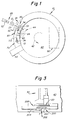
- FIG. 1 An analyzer 10 in which this shuttle invention is useful is shown in Figure 1 and preferably comprises a station 20 for loading a slide-like test element E into a sample dispensing station 30, and for loading such an element, along path 32, now bearing patient sample, into an incubator 40.
- loading station 20 includes a pusher blade 22 which pushes an element E along path 29 so as to be injected into station 30.
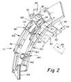
- the loading station includes tip locator 34, as shown more clearly in Figure 2, with two apertures 36, 37 as is conventional for patient sample metering, and an aperture 38 for reference liquid metering, as is also conventional.
- the incubator 40 is the rotating type, rotating in the direction of arrow 42, and includes a reflectometer 50 (Figure 1) for scanning colorimetric test elements while they are held at a plurality of stations 44, etc. ( Figure 2) as defined by a rotor 46.
- FIG. 2 An analyzer construction similar to that described in US-A-4 857 471 is shown in Figure 2.
- a wash station 70 is disposed outside of incubator 40 adn is displaced circumferentially from sample dispensing station 30.
- the wash station 70 comprises a boss 72 and aperture 74 which serve to hold a dispensing tip (not shown) in proper orientation with respect to a test element to be washed.
- an eject station 80 In between stations 30 and 70 is an eject station 80, including a discharge path defined by aperture 82 ( Figure 1) into which a test element is ejected, in the direction shown by arrow 84, when its readings are completed.
- Shuttle apparatus is then provided to allow test elements to be intercepted at station 80, taken to wash station 70, and re-inserted into the incubator, as described in US-A-4 857 471. In accordance with one aspect of the invention, it is the improvement of this apparatus to which the invention is addressed.
- the shuttle apparatus 100 shown in Figure 2, comprises a catcher plate 110, means 160 for supporting catcher plate 110 for movement along a path indicated by arrow 112 in Figure 1 which is preferably curvilinear, and means 140 for driving plate 110 along path 112.
- path 112 is constructed to extend back to station 30 to intersect path 32 so that a test element washed at station 70 can be reinserted into the loading path 32.
- catcher plate 110 comprises a frame 120 shaped to hold a test element E, shown in phantom. Accordingly, frame 120 is generally rectangular, and is provided with two opposed shoulders 122, 124 shaped and positioned, as is shown more clearly in Figure 6, to restrain element E from moving off plate 110 as the latter moves on path 112 ( Figure 4). Shoulder 122 is the leading shoulder and is preferably beveled, to allow shoulder 122 to cam under element E when the latter is returned to and retained at path 32 ( Figure 1) as described hereinafter.
- a central support member 128 is flexibly connected to frame 120 to do the principal carrying of element E.
- the flexibility is achieved by reason of the cantilever connection of support member 128 at one side 130 of frame 120.
- member 128 is able to flex relative to frame 120, in and out of the plane defined by frame 120.
- Plate 110 is preferably integrally connected to a drive tongue 132 which extends along a curvilinear arc which matches the curve of means 160 and path 112.
- the outside edge of tongue 132 has a raised ridge 134 provided with means, such as slots 136, to cooperate with a sensor.
- the inside edge 138 of tongue 132 comprises a raised ridge which is provided with a rack 139.
- Rack 139 is driven by gear 142 of drive means 140 shown in Figure 2.
- Support means 160 for plate 110 and its tongue 132 comprises two opposed track members 162 and 164 as shown in Figures 7 to 9, between which plate 110 and tongue 132 reciprocate.
- Members 162 and 164 preferably have the same arcuate curvature as tongue 132.
- member 162 is generally flat ( Figure 8) and is apertured at 82 for element discharge, and at 166 to receive drive gear 142 ( Figure 7).
- Opposed track member 164 is rail-shaped at 170, 172 to accommodate ridge 134, and rack 139 of tongue 132 ( Figure 8).
- Member 164 is secured to lower member 162 at bottom portions 174 and 176.
- Member 164 is apertured to accommodate gear 142, and further at 74, as shown in Figures 1 and 2, to provide for wash station 70.
- stop means 180 which allow a washed test element to be returned and retained at station 30 (Figure 7).
- stop means 180 is disposed adjacent the injection path 29, 32, at the intersection location of that path with path 112.
- stop means 180 comprise a flexure plate 182, as shown in Figures 2 and 7, which is cantilevered by arm 184 from the rest of upper member 164.
- the outer edge 186 of plate 182 provides a shoulder against which a test element abuts, when it moves along path 29, 32.
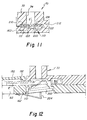
- flexure plate 182 includes on its undersurface 189, as shown in Figure 9, one and preferably two camming feet 190, 192, which allow plate 182 to ride up over a test element, as shown in Figure 12, being moved by plate 110 on path 112 to path 29, 32.
- a viewing port 196 can be provided, as shown in Figure 4, adjacent station 30 to allow a wetness detector to scan a slide element as liquid is dispensed thereon.
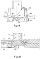
- the apparatus of the invention further includes bias means 200 at station 30, as shown more clearly in Figure 3, and locating surfaces 210, 212, as shown more clearly in Figure 11, at wash station 70.
- the bias means 200 acts to bias a test element up against the tip locator 34 at station 30.
- Means 200 comprise a platen 202 which is beveled at 203 ( Figure 12) and a spring 204 exerting an upward force F, in the direction of arrow 206 in Figure 3. Entrance slot 208 allows a test element to be inserted into station 30 and on to either platen 202 or shuttle plate 110.
- stop surface 210 is provided to stop the movement of a test element E' even as plate 110 continues to advance slightly further, in the direction of arrow 112.
- Undersurface 212 at station 70 is the ceiling against which element E' is pushed by flexible support member 128.
- An opposite depression 220 is formed in lower track member 162 to receive frame 120 of plate 110, which is cammed downwardly due to camming surface 122 of frame 120 pressing against element E'.
- a camming surface not shown, extending diagonally from surface 210 ensures proper location of element E' in the direction out of the plane of Figure 11.
- plate 110 is moved by drive means 140 into a position so as to intercept an ejected test element E' ( Figure 10) thus preventing element E' from falling out discharge aperture 82.
- plate 110 moves along path 112 due to the action of drive means 140, until element E' is at wash station 70 ( Figure 11).
- a suitable pipette not shown, is inserted into aperture 74, and boss 72 serves to hold the pipette the proper distance within station 70.
- plate 110 pulls element E' up against stop shoulder 210 and the flexure of support member 128 is such as to push element E' up against undersurface 212 of station 70.
- the proper spacing of the pipette and element E' is now defined, which can be, for example, about 1.3mm.
- About 10 ⁇ l of wash liquid is preferably ejected on to the element E', preferably at a rate of about 0.5 ⁇ l/s, for 20s. However, other rates can also be used, depending on the hydrophilicity of the element being washed.
- plate 110 is now returned towards station 30 and away from station 70, by reversing the direction of rotation of gear 142.
- the wash method differs from that previously used in that the washed element is returned to the station from which elements that have just received sample are loaded into the incubator.
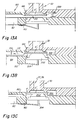
- This allows the analyzer to be simplified in that the same pusher blade used to initially load the element into the analyzer is re-used to re-load the element. More specifically, as plate 110 and element E' move from the vicinity of discharge path 82 into station 30 where path 112 intersects path 29, 32 ( Figure 12) camming surfaces 190 and 192 allow flexure plate 182 of stop means 180 to ride up over element E'. At the same time, platen 202 is cammed downwardly due to the camming action caused by surface 203.
- stop means 180 is effective to restrain element E' from leaving station 30 with plate 110. That is, shoulder 186 slips behind element E' ( Figure 13A) so that as plate 110 starts moving out of station 30 along the path of arrow 112 ( Figure 13B) shoulder 186 holds element E' from following plate 110. Plate 110 is carefully advanced into the position shown in Figure 13A by drive means 140 to ensure element E' is advanced past shoulder 186. The steps of travel of means 140 can be adjusted to ensure that this advance occurs. Meanwhile, platen 202 is pushed up by its spring 204 to further hold element E'.
- a bumper spring 300 is preferably included, as shown in Figure 13A, against which plate 110 pushes when element E' is being returned to station 30. This spring prevents over-travel of plate 110, but primarily it assists in holding test elements against stop shoulder 186 ( Figure 13B).
Landscapes
- Health & Medical Sciences (AREA)
- Life Sciences & Earth Sciences (AREA)
- Immunology (AREA)
- Chemical & Material Sciences (AREA)
- Engineering & Computer Science (AREA)
- Biochemistry (AREA)
- General Health & Medical Sciences (AREA)
- General Physics & Mathematics (AREA)
- Analytical Chemistry (AREA)
- Pathology (AREA)
- Physics & Mathematics (AREA)
- Urology & Nephrology (AREA)
- Hematology (AREA)
- Molecular Biology (AREA)
- Biomedical Technology (AREA)
- Biotechnology (AREA)
- Cell Biology (AREA)
- Microbiology (AREA)
- Food Science & Technology (AREA)
- Medicinal Chemistry (AREA)
- Automatic Analysis And Handling Materials Therefor (AREA)
- Apparatus Associated With Microorganisms And Enzymes (AREA)
Applications Claiming Priority (3)
| Application Number | Priority Date | Filing Date | Title |
|---|---|---|---|
| US07/615,530 US5174960A (en) | 1990-11-19 | 1990-11-19 | Apparatus for shuttling a test element from a discharge path to a wash station |
| US615530 | 1990-11-19 | ||
| EP91202977A EP0487149B1 (de) | 1990-11-19 | 1991-11-15 | Testelementfördervorrichtung für Analysatoren |
Related Parent Applications (1)
| Application Number | Title | Priority Date | Filing Date |
|---|---|---|---|
| EP91202977.4 Division | 1991-11-15 |
Publications (1)
| Publication Number | Publication Date |
|---|---|
| EP0639773A1 true EP0639773A1 (de) | 1995-02-22 |
Family
ID=24465795
Family Applications (2)
| Application Number | Title | Priority Date | Filing Date |
|---|---|---|---|
| EP91202977A Expired - Lifetime EP0487149B1 (de) | 1990-11-19 | 1991-11-15 | Testelementfördervorrichtung für Analysatoren |
| EP94116615A Ceased EP0639773A1 (de) | 1990-11-19 | 1991-11-15 | Analysatoren und Testelementfördervorrichtung dafür |
Family Applications Before (1)
| Application Number | Title | Priority Date | Filing Date |
|---|---|---|---|
| EP91202977A Expired - Lifetime EP0487149B1 (de) | 1990-11-19 | 1991-11-15 | Testelementfördervorrichtung für Analysatoren |
Country Status (8)
| Country | Link |
|---|---|
| US (1) | US5174960A (de) |
| EP (2) | EP0487149B1 (de) |
| JP (1) | JP3068286B2 (de) |
| KR (1) | KR920010286A (de) |
| CA (1) | CA2054454A1 (de) |
| DE (1) | DE69124929T2 (de) |
| HK (1) | HK114797A (de) |
| IE (1) | IE914017A1 (de) |
Families Citing this family (35)
| Publication number | Priority date | Publication date | Assignee | Title |
|---|---|---|---|---|
| US5196168A (en) * | 1991-12-19 | 1993-03-23 | Eastman Kodak Company | Incubator with positioning device for slide elements |
| US5380487A (en) * | 1992-05-05 | 1995-01-10 | Pasteur Sanofi Diagnostics | Device for automatic chemical analysis |
| US5340540A (en) * | 1993-05-03 | 1994-08-23 | Eastman Kodak Company | Cap raising mechanism for an incubator |
| DE69431544T2 (de) * | 1993-07-16 | 2003-02-27 | Fuji Photo Film Co., Ltd. | Biochemischer Analysator und Inkubator dafür |
| US5525514A (en) * | 1994-04-06 | 1996-06-11 | Johnson & Johnson Clinical Diagnostics, Inc. | Wash detection method for dried chemistry test elements |
| US5599501A (en) * | 1994-11-10 | 1997-02-04 | Ciba Corning Diagnostics Corp. | Incubation chamber |
| US5611996A (en) * | 1995-06-06 | 1997-03-18 | Johnson & Johnson Clinical Diagnostics, Inc. | Slide test element holder with minimized Z-axis variability |
| US5641688A (en) * | 1995-06-06 | 1997-06-24 | Johnson & Johnson Clinical Diagnostics, Inc. | Immunoassay including washing a slide at different locations |
| US5795784A (en) | 1996-09-19 | 1998-08-18 | Abbott Laboratories | Method of performing a process for determining an item of interest in a sample |
| US5856194A (en) | 1996-09-19 | 1999-01-05 | Abbott Laboratories | Method for determination of item of interest in a sample |
| US6281568B1 (en) | 1998-10-21 | 2001-08-28 | Amkor Technology, Inc. | Plastic integrated circuit device package and leadframe having partially undercut leads and die pad |
| KR200309906Y1 (ko) | 1999-06-30 | 2003-04-14 | 앰코 테크놀로지 코리아 주식회사 | 반도체 패키지 제조용 리드프레임 |
| KR100526844B1 (ko) | 1999-10-15 | 2005-11-08 | 앰코 테크놀로지 코리아 주식회사 | 반도체패키지 및 그 제조방법 |
| KR100364978B1 (ko) | 1999-10-15 | 2002-12-16 | 앰코 테크놀로지 코리아 주식회사 | 반도체패키지의 와이어 본딩용 클램프 및 히트블록 |
| KR100355795B1 (ko) | 1999-10-15 | 2002-10-19 | 앰코 테크놀로지 코리아 주식회사 | 반도체패키지 및 그 제조 방법 |
| KR100355796B1 (ko) | 1999-10-15 | 2002-10-19 | 앰코 테크놀로지 코리아 주식회사 | 반도체패키지용 리드프레임 및 이를 봉지하기 위한 금형 구조 |
| KR20010037254A (ko) | 1999-10-15 | 2001-05-07 | 마이클 디. 오브라이언 | 반도체패키지 |
| KR20010037252A (ko) | 1999-10-15 | 2001-05-07 | 마이클 디. 오브라이언 | 반도체패키지 제조용 금형 |
| US6525406B1 (en) | 1999-10-15 | 2003-02-25 | Amkor Technology, Inc. | Semiconductor device having increased moisture path and increased solder joint strength |
| KR100355794B1 (ko) | 1999-10-15 | 2002-10-19 | 앰코 테크놀로지 코리아 주식회사 | 리드프레임 및 이를 이용한 반도체패키지 |
| KR20010037247A (ko) | 1999-10-15 | 2001-05-07 | 마이클 디. 오브라이언 | 반도체패키지 |
| KR20010056618A (ko) | 1999-12-16 | 2001-07-04 | 프랑크 제이. 마르쿠치 | 반도체패키지 |
| US6847103B1 (en) | 1999-11-09 | 2005-01-25 | Amkor Technology, Inc. | Semiconductor package with exposed die pad and body-locking leadframe |
| KR100421774B1 (ko) | 1999-12-16 | 2004-03-10 | 앰코 테크놀로지 코리아 주식회사 | 반도체패키지 및 그 제조 방법 |
| KR100426494B1 (ko) | 1999-12-20 | 2004-04-13 | 앰코 테크놀로지 코리아 주식회사 | 반도체 패키지 및 이것의 제조방법 |
| KR20010058583A (ko) | 1999-12-30 | 2001-07-06 | 마이클 디. 오브라이언 | 리드 엔드 그리드 어레이 반도체패키지 |
| US6756658B1 (en) | 2001-04-06 | 2004-06-29 | Amkor Technology, Inc. | Making two lead surface mounting high power microleadframe semiconductor packages |
| KR100436754B1 (ko) * | 2001-05-26 | 2004-06-22 | 주식회사 호산기술 | 휴대용 드릴링 머신 |
| US8262991B2 (en) * | 2003-05-19 | 2012-09-11 | Lattec I/S | Apparatus for analysing fluid taken from a body |
| US7273591B2 (en) * | 2003-08-12 | 2007-09-25 | Idexx Laboratories, Inc. | Slide cartridge and reagent test slides for use with a chemical analyzer, and chemical analyzer for same |
| US7588733B2 (en) | 2003-12-04 | 2009-09-15 | Idexx Laboratories, Inc. | Retaining clip for reagent test slides |
| US9116129B2 (en) | 2007-05-08 | 2015-08-25 | Idexx Laboratories, Inc. | Chemical analyzer |
| WO2015106008A1 (en) | 2014-01-10 | 2015-07-16 | Idexx Laboratories, Inc. | Chemical analyzer |
| KR20230047123A (ko) | 2020-07-10 | 2023-04-06 | 아이덱스 래보러토리즈, 인코포레이티드 | 현장 의료 진단 분석기 및 샘플의 의료 진단 분석 장치, 시스템, 및 방법 |
| CN113029883B (zh) * | 2021-03-24 | 2022-04-12 | 江苏瑞城检测技术有限公司 | 一种用于空气消毒效果的检测设备 |
Citations (4)
| Publication number | Priority date | Publication date | Assignee | Title |
|---|---|---|---|---|
| DE79712C (de) * | ||||
| US4224032A (en) * | 1976-12-17 | 1980-09-23 | Eastman Kodak Company | Method and apparatus for chemical analysis |
| EP0231951A2 (de) * | 1986-02-07 | 1987-08-12 | Fuji Photo Film Co., Ltd. | Gerät für chemische Analysen |
| DE8804264U1 (de) * | 1988-03-29 | 1988-05-19 | Boehringer Mannheim Gmbh, 6800 Mannheim | Vorrichtung zur Überführung eines Teststreifens von einer ersten Unterlage zu einer zweiten Unterlage |
Family Cites Families (8)
| Publication number | Priority date | Publication date | Assignee | Title |
|---|---|---|---|---|
| US4152390A (en) * | 1976-12-17 | 1979-05-01 | Eastman Kodak Company | Chemical analyzer |
| US4219929A (en) * | 1979-01-29 | 1980-09-02 | Manki Min | Finger-toe nail clipper having shifting receptacle |
| US4302420A (en) * | 1981-01-09 | 1981-11-24 | Eastman Kodak Company | Analyzer featuring a contacting reflectometer |
| US4424191A (en) * | 1982-03-04 | 1984-01-03 | Eastman Kodak Company | Analyzer featuring loading and unloading means for a storage chamber, and common drive means |
| JPS61198041A (ja) * | 1985-02-28 | 1986-09-02 | Konishiroku Photo Ind Co Ltd | 生化学分析装置 |
| US4710352A (en) * | 1985-09-20 | 1987-12-01 | Eastman Kodak Company | Simplified test element advancing mechanism having positive engagement with element |
| JPH0442777Y2 (de) * | 1986-09-03 | 1992-10-09 | ||
| US4857471A (en) * | 1987-07-20 | 1989-08-15 | Eastman Kodak Company | Analyzer with wash station separate from incubator |
-
1990
- 1990-11-19 US US07/615,530 patent/US5174960A/en not_active Expired - Lifetime
-
1991
- 1991-10-29 CA CA002054454A patent/CA2054454A1/en not_active Abandoned
- 1991-11-15 EP EP91202977A patent/EP0487149B1/de not_active Expired - Lifetime
- 1991-11-15 EP EP94116615A patent/EP0639773A1/de not_active Ceased
- 1991-11-15 DE DE69124929T patent/DE69124929T2/de not_active Expired - Fee Related
- 1991-11-18 JP JP3302101A patent/JP3068286B2/ja not_active Expired - Lifetime
- 1991-11-19 IE IE401791A patent/IE914017A1/en not_active Application Discontinuation
- 1991-11-19 KR KR1019910020617A patent/KR920010286A/ko not_active Withdrawn
-
1997
- 1997-06-26 HK HK114797A patent/HK114797A/en not_active IP Right Cessation
Patent Citations (4)
| Publication number | Priority date | Publication date | Assignee | Title |
|---|---|---|---|---|
| DE79712C (de) * | ||||
| US4224032A (en) * | 1976-12-17 | 1980-09-23 | Eastman Kodak Company | Method and apparatus for chemical analysis |
| EP0231951A2 (de) * | 1986-02-07 | 1987-08-12 | Fuji Photo Film Co., Ltd. | Gerät für chemische Analysen |
| DE8804264U1 (de) * | 1988-03-29 | 1988-05-19 | Boehringer Mannheim Gmbh, 6800 Mannheim | Vorrichtung zur Überführung eines Teststreifens von einer ersten Unterlage zu einer zweiten Unterlage |
Also Published As
| Publication number | Publication date |
|---|---|
| DE69124929D1 (de) | 1997-04-10 |
| EP0487149A3 (en) | 1993-03-03 |
| EP0487149A2 (de) | 1992-05-27 |
| US5174960A (en) | 1992-12-29 |
| JPH04291158A (ja) | 1992-10-15 |
| DE69124929T2 (de) | 1997-07-03 |
| CA2054454A1 (en) | 1992-05-20 |
| IE914017A1 (en) | 1992-05-20 |
| JP3068286B2 (ja) | 2000-07-24 |
| KR920010286A (ko) | 1992-06-26 |
| HK114797A (en) | 1997-08-29 |
| EP0487149B1 (de) | 1997-03-05 |
Similar Documents
| Publication | Publication Date | Title |
|---|---|---|
| EP0487149B1 (de) | Testelementfördervorrichtung für Analysatoren | |
| AU671663B2 (en) | Assay module transport apparatus for use in an automated analytical instrument | |
| AU630847B2 (en) | Slide analysis system | |
| AU668204B2 (en) | Automated analytical instrument having a fluid sample holding tray transport assembly | |
| EP0223002B1 (de) | Automatischer Analysator mit freiem Zugang zur Probe | |
| EP0657031B1 (de) | Vorrichtung und verfahren zur foerderung und zeitlichen lagerung von probenroehrchen bei einem automatischen chemischen analysator | |
| US5055262A (en) | Automatic cuvette loading apparatus | |
| CA1230327A (en) | Method and apparatus for transporting carriers of sealed sample tubes and mixing the samples | |
| CA1057529A (en) | Automatic test sample handling system | |
| JP3880658B2 (ja) | 試料ラックおよびそれを移動させる装置並びに方法 | |
| US6818182B2 (en) | Device for processing samples of blood products | |
| JP6573524B2 (ja) | 検体ラック搬送装置及び自動分析システム | |
| EP0866335A2 (de) | Automatische Vorrichtung zur Probenentnahme aus geschlossenen Behältern | |
| US5244632A (en) | Apparatus for shuttling a test element from a discharge path to a wash station | |
| AU652278B2 (en) | Assay module transfer apparatus for use in an automated analytical instrument | |
| JPS58131567A (ja) | 化学分析用キユベツトマガジン |
Legal Events
| Date | Code | Title | Description |
|---|---|---|---|
| PUAI | Public reference made under article 153(3) epc to a published international application that has entered the european phase |
Free format text: ORIGINAL CODE: 0009012 |
|
| 17P | Request for examination filed |
Effective date: 19941021 |
|
| AC | Divisional application: reference to earlier application |
Ref document number: 487149 Country of ref document: EP |
|
| AK | Designated contracting states |
Kind code of ref document: A1 Designated state(s): BE CH DE FR GB IT LI LU NL |
|
| RAP1 | Party data changed (applicant data changed or rights of an application transferred) |
Owner name: CLINICAL DIAGNOSTIC SYSTEMS, INC. |
|
| RAP1 | Party data changed (applicant data changed or rights of an application transferred) |
Owner name: JOHNSON & JOHNSON CLINICAL DIAGNOSTICS, INC. |
|
| 17Q | First examination report despatched |
Effective date: 19971001 |
|
| GRAG | Despatch of communication of intention to grant |
Free format text: ORIGINAL CODE: EPIDOS AGRA |
|
| STAA | Information on the status of an ep patent application or granted ep patent |
Free format text: STATUS: THE APPLICATION HAS BEEN REFUSED |
|
| 18R | Application refused |
Effective date: 19980905 |