EP0638422B1 - Dispositif de pulvérisation de liquides pour machines d'impression - Google Patents
Dispositif de pulvérisation de liquides pour machines d'impression Download PDFInfo
- Publication number
- EP0638422B1 EP0638422B1 EP94107096A EP94107096A EP0638422B1 EP 0638422 B1 EP0638422 B1 EP 0638422B1 EP 94107096 A EP94107096 A EP 94107096A EP 94107096 A EP94107096 A EP 94107096A EP 0638422 B1 EP0638422 B1 EP 0638422B1
- Authority
- EP
- European Patent Office
- Prior art keywords
- pump
- valve
- piston
- suction stroke
- liquid
- Prior art date
- Legal status (The legal status is an assumption and is not a legal conclusion. Google has not performed a legal analysis and makes no representation as to the accuracy of the status listed.)
- Expired - Lifetime
Links
- 239000007788 liquid Substances 0.000 title claims description 60
- 239000007921 spray Substances 0.000 title description 17
- 230000006835 compression Effects 0.000 claims description 7
- 238000007906 compression Methods 0.000 claims description 7
- 238000011144 upstream manufacturing Methods 0.000 claims description 5
- 238000000034 method Methods 0.000 claims description 4
- 238000005406 washing Methods 0.000 claims description 3
- XLYOFNOQVPJJNP-UHFFFAOYSA-N water Substances O XLYOFNOQVPJJNP-UHFFFAOYSA-N 0.000 claims description 3
- 239000003599 detergent Substances 0.000 claims description 2
- 239000004744 fabric Substances 0.000 claims description 2
- 239000000203 mixture Substances 0.000 claims description 2
- 239000002904 solvent Substances 0.000 claims description 2
- 230000001419 dependent effect Effects 0.000 claims 1
- 239000000080 wetting agent Substances 0.000 claims 1
- 238000004140 cleaning Methods 0.000 description 1
- 230000008602 contraction Effects 0.000 description 1
- 230000007423 decrease Effects 0.000 description 1
- 239000000463 material Substances 0.000 description 1
- 239000007787 solid Substances 0.000 description 1
- 238000005507 spraying Methods 0.000 description 1
- 239000000758 substrate Substances 0.000 description 1
Images


Classifications
-
- B—PERFORMING OPERATIONS; TRANSPORTING
- B41—PRINTING; LINING MACHINES; TYPEWRITERS; STAMPS
- B41F—PRINTING MACHINES OR PRESSES
- B41F7/00—Rotary lithographic machines
- B41F7/20—Details
- B41F7/24—Damping devices
-
- B—PERFORMING OPERATIONS; TRANSPORTING
- B05—SPRAYING OR ATOMISING IN GENERAL; APPLYING FLUENT MATERIALS TO SURFACES, IN GENERAL
- B05B—SPRAYING APPARATUS; ATOMISING APPARATUS; NOZZLES
- B05B9/00—Spraying apparatus for discharge of liquids or other fluent material, without essentially mixing with gas or vapour
- B05B9/03—Spraying apparatus for discharge of liquids or other fluent material, without essentially mixing with gas or vapour characterised by means for supplying liquid or other fluent material
- B05B9/04—Spraying apparatus for discharge of liquids or other fluent material, without essentially mixing with gas or vapour characterised by means for supplying liquid or other fluent material with pressurised or compressible container; with pump
- B05B9/0403—Spraying apparatus for discharge of liquids or other fluent material, without essentially mixing with gas or vapour characterised by means for supplying liquid or other fluent material with pressurised or compressible container; with pump with pumps for liquids or other fluent material
- B05B9/0413—Spraying apparatus for discharge of liquids or other fluent material, without essentially mixing with gas or vapour characterised by means for supplying liquid or other fluent material with pressurised or compressible container; with pump with pumps for liquids or other fluent material with reciprocating pumps, e.g. membrane pump, piston pump, bellow pump
-
- B—PERFORMING OPERATIONS; TRANSPORTING
- B41—PRINTING; LINING MACHINES; TYPEWRITERS; STAMPS
- B41F—PRINTING MACHINES OR PRESSES
- B41F31/00—Inking arrangements or devices
-
- B—PERFORMING OPERATIONS; TRANSPORTING
- B41—PRINTING; LINING MACHINES; TYPEWRITERS; STAMPS
- B41F—PRINTING MACHINES OR PRESSES
- B41F35/00—Cleaning arrangements or devices
-
- B—PERFORMING OPERATIONS; TRANSPORTING
- B41—PRINTING; LINING MACHINES; TYPEWRITERS; STAMPS
- B41P—INDEXING SCHEME RELATING TO PRINTING, LINING MACHINES, TYPEWRITERS, AND TO STAMPS
- B41P2235/00—Cleaning
- B41P2235/10—Cleaning characterised by the methods or devices
- B41P2235/26—Spraying devices
Definitions
- the invention relates to a part of a printing press which has a liquid spray device, according to the preamble of claim 1.
- Such a liquid spray device for printing presses is known from DE-OS 28 26 135 and serves there as a blanket washing device.
- Piston pumps draw a certain amount of liquid from a liquid container during a suction stroke and then press it during the pressure stroke into a memory of a nozzle bar, from which the liquid is then expelled by a blast of compressed air through nozzle openings in the nozzle bar and sprayed onto a blanket cylinder of a printing machine to be washed becomes.
- US-A-4 991 747 and US-A-5 192 006 disclose manual spray devices which spray spray liquid by means of a piston pump.
- the liquid spray device according to the invention is suitable for both spraying techniques.
- the liquid is pressed out of the nozzle openings of the nozzle device by the pressure of the piston pump and is sprayed by the pressure of the piston pump.
- the liquid spray device according to the invention is suitable for supplying water, liquid detergent, solvent or a mixture thereof or of printing process liquid to any parts in a printing press, such as for example on a blanket cylinder, printing plate cylinder, printing cylinder, on inking unit rollers, dampening unit rollers or on a cleaning cloth Wash these cylinders or rollers or the substrate.
- a printing press such as for example on a blanket cylinder, printing plate cylinder, printing cylinder, on inking unit rollers, dampening unit rollers or on a cleaning cloth Wash these cylinders or rollers or the substrate.
- the basic structure of a printing press is known for example from DE-OS 40 13 465 A1.
- the object of the invention is to solve the problem of dripping and deforming the spray jet into a solid liquid jet which is self-contained, and to avoid moisture stains and liquid streaks thereby generated on an object sprayed with the liquid at the end of a pressure stroke of the piston pump.
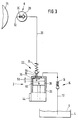
- the liquid spray device for printing presses shown in the drawings contains a piston pump 2; a liquid container 4 with liquid 6; a nozzle device 8; a suction line 12 fluidly connecting the liquid container 4 with a suction inlet 10 of the piston pump 2; a pump inlet valve 14 arranged in the flow path of the suction line 12 in the form of a check valve opening in the flow direction towards the piston pump 2 with a compression spring 16 urging the valve in the opposite flow direction in the closed position; a pressure line 20 fluidly connecting a pressure outlet 18 of the piston pump 2 to the nozzle device 8; a arranged in the flow path of the pressure line 20 pump outlet valve 22, which opens in the flow direction from the piston pump 2 to the nozzle device 8 and is pushed in the opposite closing direction by a compression spring 24 in the closed position.
- the pump inlet valve 14 can be arranged according to the drawings in the suction line 12 or on the pump housing 26.
- the pump outlet valve 22 can be arranged in the pressure line 20 or on the pump housing 26.
- the pump inlet valve 14 and the pump outlet valve 22 can be integrated in the housing 26 or in a housing cover, as is known from DE-OS 41 36 265 A1.
- the nozzle device 8 contains a check valve 28 opening in the pressure direction of the piston pump 2 with a spring 30 urging the check valve 28 in the opposite direction into the closed position and at least one nozzle opening 32, which extends over the length of a printing press cylinder 34 to be moistened with the liquid, or a large number of nozzle openings 32, which are arranged distributed over the length of the printing press cylinder 34 to be moistened.
- the pump outlet valve 22 is connected upstream of an additional valve 36, 40, which closes suddenly when the pump piston 38 reaches its pressure stroke end position during the pressure stroke, which is shown in FIG. 1 is shown, and which opens suddenly when the pump piston 38 starts a suction stroke movement from this pressure stroke end position.
- the additional valve 36, 40 consists of a valve seat 36 which surrounds the pressure outlet 18 in a ring in the pump housing 26 and an end face 40 of the pump piston 38 opposite it as a valve disk which closes the valve seat 36 at the end of the pressure stroke of the pump piston 38.
- the pressure outlet 18 and the suction inlet 10 are located side by side in the same end wall 42 of the pump housing 26. They could also be arranged differently.
- the valve seat 36 forms a stop against which the pump piston 38 bears at the end of its pressure stroke path and which thereby limits the pressure stroke path.
- a control device 44 which can be a microprocessor-controlled electronic control device, controls the pump piston 38 in such a way that when it reaches the valve seat 36 at the end of a pressure stroke it is suddenly moved away from the valve seat 36 in the opposite direction of the suction stroke. Furthermore, the control stroke 44 can be used to set or meter the suction stroke distance of the pump piston 38 and thus the amount of liquid which the pump piston 38 sprays onto the cylinder 34 via its nozzle openings 32 during a subsequent pressure stroke through the nozzle device 8. In order to the amount of liquid delivered during a delivery stroke is identical to the amount of liquid sprayed through the nozzle openings 32, it is of course necessary that the pressure line 20 has been filled with liquid by one or more previous delivery strokes of the pump piston 38.
- FIG. 1 shows the liquid spray device when the pump piston 38 performs a suction stroke movement in the direction of an arrow 46.
- the pump outlet valve 22 and the check valve 28 of the nozzle device 8 are relieved and closed both by the suction effect of the pump piston 38 and by their compression springs 24 and 30.
- the suction force of the pump piston 38 outweighs the closing force of the spring 16 of the pump inlet valve 14, so that the pump inlet valve 14 is opened and liquid 6 is sucked out of the liquid container 4 through the suction line 12 into the pump housing 26.
- the piston movement is reversed and the pump piston 38 carries out a pressure stroke in accordance with an arrow 48 until it bears against the valve seat 36 of the additional valve formed in the pump housing 26 and against it closes, as shown in FIG. 2.
- the previously sucked-in liquid is sprayed by the nozzle device 8 in the form of a spray jet 50 onto the printing press cylinder 34. Due to the pressure stroke movement of the pump piston 38, the pump inlet valve 14 closed and the pump outlet valve 22 and the check valve 28 of the nozzle device 8 are opened against the force of their springs 24 and 30.
- valve body 52 of the pump outlet valve 22 is provided with a valve tappet 54, which extends through the valve seat 36 formed in the pump housing 26 a distance 56 beyond this valve seat 36 into the pump housing 26 in the direction of the pump piston 38 when the valve body 52 of the Pump outlet valve 22 is in the closed position shown in Figures 1 and 3.
- the plunger distance 56 projecting beyond the valve seat 36 can be the same size, smaller or larger than the distance by which the valve body 52 is moved in the opening direction by the liquid pressure generated by the pump piston 38 during the pressure stroke movement.
- the pressure line 20 expands slightly due to the elasticity of its material. This expansion decreases and the line volume shrinks accordingly when the liquid pressure drops at the end of the pressure stroke because of the liquid escaping from the nozzle openings 32. This can result in dripping of liquid at the nozzle openings 32 if no special countermeasures are taken. In the present case, there are the countermeasures in the valve tappet 54 and in the additional valve with the valve seat 36, which each prevent such dripping.
- the valve seat 36 at the upstream beginning of the pressure outlet 18 with respect to the pressure stroke means that, when the pressure stroke end has been reached, the pump piston 38 can suddenly no longer exert pressure on the liquid in the pressure line 20.
- the pump piston 38 As soon as the pump piston 38 has reached the end of the pressure stroke shown in FIG. 2, it is suddenly and quickly moved again by the control device 44 away from the valve seat 36 in the suction stroke direction 46, so that a pressure relief quickly sets in in the pressure line 20 and in the nozzle device 8 and Liquid from the pressure line 20 and the nozzle device 8 is sucked back into the pump housing 26 through the pump outlet valve 22 which is kept open by means of the tappet 54.
- valve tappet 54 is provided, which upon a closing movement of the valve body 52 of the pump outlet valve 22 is applied to the pump piston 38 and prevents the pump outlet valve 22 from closing completely until the pump piston 38 has covered the suction stroke distance 56 according to FIG. 3, which is equal to the distance 56 by which the valve tappet 34 with the outlet valve 22 closed the valve seat 36 of the additional valve protrudes into the pump housing 26.
- the pressure line 20 has sufficient time during this suction stroke start section 56 to reduce the liquid pressure and liquid in its quantity and speed back into the pump housing 26 in such a way that drip-free is ensured at the nozzle openings 32.
- the closing force of the spring 16 of the pump inlet valve 14 is set to a closing force threshold value such that the vacuum generated by the pump piston 38 during the initial suction stroke section 56 is not sufficient to open the pump inlet valve 14.
- This closing pressure threshold value of the inlet valve 14 can be in the range between 0.3 and 1 bar. It is preferably 0.6 bar.
- valve seat 36 of the additional valve projects into the housing interior via the pump housing 26.
- the suction inlet 10 remains open to the interior of the housing even when the pump piston 38 bears on the valve seat 36 of the additional valve, as shown in FIG. 2.
Landscapes
- Engineering & Computer Science (AREA)
- Mechanical Engineering (AREA)
- Details Of Reciprocating Pumps (AREA)
- Reciprocating Pumps (AREA)
- Rotary Presses (AREA)
- Nozzles (AREA)
Claims (12)
- Partie d'une machine d'impression comportant un dispositif de pulvérisation d'un liquide qui présente les caractéristiques suivantes :
une pompe à piston (2) pour amener une quantité dosée, laquelle dépend du trajet sur la course d'aspiration du piston, d'un liquide comme par exemple de l'eau, un détergent, un solvant, un agent de mouillage ou un mélange de ceux-ci, ou un liquide servant à un processus sous pression, jusqu'à un dispositif à buses (8) au moyen duquel le liquide est pulvérisé sur une partie d'une machine d'impression, comme par exemple sur un cylindre porte-blanchet, un cylindre porte-clichés ou un cylindre de contre-pression, ou sur des rouleaux encreurs ou des rouleaux mouilleurs, ou sur un chiffon de lavage pour nettoyer de tels cylindres ou rouleaux ou la matière imprimée ;
une soupape d'entrée (14) de la pompe dans un conduit d'aspiration (12) qui relie quant à l'écoulement un réservoir de liquide (4) à une entrée d'aspiration (10) de la pompe à piston (2) ;
une soupape de sortie (22) de la pompe dans un conduit de refoulement (20) qui relie quant à l'écoulement une sortie de refoulement (18) de la pompe à piston (2) au dispositif à buses (8) ;
cependant que la soupape d'entrée (14) est ouverte et la soupape de sortie (22) est fermée pendant la course d'aspiration du piston (38) de la pompe, et que la soupape d'entrée (14) est fermée et la soupape de sortie (22) est ouverte pendant la course de refoulement,
caractérisée par le fait qu'il est prévu des moyens (54) pour retarder la fermeture grâce auxquels la soupape de sortie (22) est maintenue dans la position d'ouverture au début de la course d'aspiration du piston (38) de la pompe sur un trajet prédéterminé (56) du début de la course d'aspiration, et que c'est seulement ensuite qu'elle se ferme complètement, et :
par le fait qu'il est prévu des moyens (16) pour retarder l'ouverture grâce auxquels la soupape d'entrée (14) est maintenue dans la position de fermeture au début de la course d'aspiration, à peu près jusqu'à la fin du trajet prédéterminé (56) du début de la course d'aspiration, et qu'elle ne s'ouvre complètement que lorsque le piston (38) de la pompe est déplacé dans la direction (46) de la course d'aspiration au-delà de la fin du trajet (56) du début de la course d'aspiration, et :
par le fait que les moyens (16) pour retarder l'ouverture sont des moyens à ressort (16) dont la force de fermeture de la soupape est supérieure à la force d'aspiration engendrée par le piston (38) de la pompe pendant le trajet (56) du début de la course d'aspiration lorsque la soupape de sortie (22) de la pompe est ouverte, mais inférieure à la force d'aspiration engendrée par le piston (38) de la pompe lors d'une course d'aspiration dépassant le trajet (56) du début de la course d'aspiration, la soupape de sortie (22) de la pompe étant alors fermée. - Dispositif de pulvérisation d'un liquide selon la revendication 1, caractérisé par le fait que les moyens (54) pour retarder la fermeture sont des moyens mécaniques de commande forcée entre le piston (38) de la pompe et la soupape de sortie (22).
- Dispositif de pulvérisation d'un liquide selon la revendication 2, caractérisé par le fait que les moyens de commande forcée sont constitués par un poussoir (54) qui agit sur la soupape de sortie (22) et qui peut être actionné par le piston (38) de la pompe.
- Dispositif de pulvérisation d'un liquide selon l'une des revendications précédentes, caractérisé par le fait que la soupape de sortie (22) est une soupape anti-retour s'ouvrant dans la direction de l'écoulement qui s'éloigne de la pompe à piston (2).
- Dispositif de pulvérisation d'un liquide selon l'une des revendications précédentes, caractérisé par le fait que les moyens à ressort (16) peuvent être réglés sur une force déterminée de fermeture de la soupape.
- Dispositif de pulvérisation d'un liquide selon la revendication 5, caractérisé par le fait que les moyens à ressort (16) de la soupape d'entrée (14) sont réglés sur une force de fermeture qui correspond à une pression comprise entre 0,3 et 1 bar, et de préférence égale à 0,6 bar environ.
- Dispositif de pulvérisation d'un liquide selon l'une des revendications précédentes, caractérisé par le fait que la soupape d'entrée (14) de la pompe est une soupape anti-retour qui est soumise à l'action d'un ressort et qui s'ouvre dans la direction de l'écoulement vers la pompe à piston (2).
- Dispositif de pulvérisation d'un liquide selon l'une des revendications précédentes, caractérisé par le fait qu'un siège de soupape (36) qui est fermé par le piston (38) de la pompe à la fin de la course de refoulement est monté avant la sortie de refoulement (18) en un endroit situé en amont lorsqu'il est vu dans la direction de la course de refoulement.
- Dispositif de pulvérisation d'un liquide selon la revendication 8, caractérisé par le fait que le siège de soupape (36) qui est monté avant la sortie de refoulement (18) présente la forme d'une nervure annulaire, et par le fait qu'une partie du piston (38) de la pompe qui agit comme un clapet de soupape constitue une soupape à siège plan avec le siège de soupape (36).
- Dispositif de pulvérisation d'un liquide selon l'une des revendications précédentes, caractérisé par le fait que la course d'aspiration du piston (38) de la pompe est réglable (44).
- Dispositif de pulvérisation d'un liquide selon l'une des revendications précédentes, caractérisé par un dispositif d'asservissement (44) qui fait en sorte que le piston (38) de la pompe, lorsqu'il atteint la fin de sa course de refoulement, parcourt immédiatement une course d'aspiration dans la direction opposée, du moins sur ledit trajet (56) du début de la course d'aspiration.
- Dispositif de pulvérisation d'un liquide selon l'une des revendications précédentes, caractérisé par le fait que la soupape d'entrée (14) de la pompe et la soupape de sortie (22) de la pompe sont intégrées à la pompe à piston (2).
Applications Claiming Priority (2)
| Application Number | Priority Date | Filing Date | Title |
|---|---|---|---|
| DE9311935U DE9311935U1 (de) | 1993-08-10 | 1993-08-10 | Flüssigkeits-Sprühvorrichtung für Druckmaschinen |
| DE9311935U | 1993-08-10 |
Publications (2)
| Publication Number | Publication Date |
|---|---|
| EP0638422A1 EP0638422A1 (fr) | 1995-02-15 |
| EP0638422B1 true EP0638422B1 (fr) | 1996-11-13 |
Family
ID=6896609
Family Applications (1)
| Application Number | Title | Priority Date | Filing Date |
|---|---|---|---|
| EP94107096A Expired - Lifetime EP0638422B1 (fr) | 1993-08-10 | 1994-05-06 | Dispositif de pulvérisation de liquides pour machines d'impression |
Country Status (2)
| Country | Link |
|---|---|
| EP (1) | EP0638422B1 (fr) |
| DE (2) | DE9311935U1 (fr) |
Families Citing this family (5)
| Publication number | Priority date | Publication date | Assignee | Title |
|---|---|---|---|---|
| DE19503950B4 (de) * | 1995-02-07 | 2004-10-28 | Heidelberger Druckmaschinen Ag | Wascheinrichtung im Druckwerk von Druckmaschinen |
| DE19519432C2 (de) * | 1995-05-26 | 1999-06-24 | Flach Karl Heinz | Verfahren und Vorrichtung zum Versprühen einer Flüssigkeit |
| DE19938414B4 (de) * | 1999-08-13 | 2004-12-02 | Koenig & Bauer Ag | Einrichtung zum Aufbringen von einem Reinigungsmedium |
| CN111299006A (zh) * | 2020-03-13 | 2020-06-19 | 深圳市奥科立自动化有限公司 | 雾化系统的雾化方法及雾化系统 |
| CN112248637A (zh) * | 2020-09-23 | 2021-01-22 | 马鞍山虹润彩印有限责任公司 | 一种食品包装印刷用油墨自动添加装置 |
Family Cites Families (7)
| Publication number | Priority date | Publication date | Assignee | Title |
|---|---|---|---|---|
| US3508711A (en) * | 1967-12-29 | 1970-04-28 | Ryco Graphic Mfg | Fluid dispensing system |
| US4050378A (en) * | 1974-10-17 | 1977-09-27 | Smith R.P.M. Corporation | Metered spray dampening system |
| US4230160A (en) * | 1978-12-11 | 1980-10-28 | National Instrument Company, Inc. | Adjustable suck-back device for sanitary pumps |
| US5005478A (en) * | 1987-12-16 | 1991-04-09 | Precision Engineered Systems Inc. | Blanket wash system with sub-ambient pressure circulation |
| US4991747A (en) * | 1988-10-11 | 1991-02-12 | Risdon Corporation | Sealing pump |
| FR2668547B1 (fr) * | 1990-10-30 | 1992-12-24 | Bendix Europ Services Tech | Pompe a piston alternatif comportant une chambre de sortie a volume variable, notamment pour circuit de freinage. |
| US5192006A (en) * | 1991-05-01 | 1993-03-09 | Risdon Corporation | Low profile pump |
-
1993
- 1993-08-10 DE DE9311935U patent/DE9311935U1/de not_active Expired - Lifetime
-
1994
- 1994-05-06 EP EP94107096A patent/EP0638422B1/fr not_active Expired - Lifetime
- 1994-05-06 DE DE59401032T patent/DE59401032D1/de not_active Expired - Lifetime
Also Published As
| Publication number | Publication date |
|---|---|
| DE59401032D1 (de) | 1996-12-19 |
| EP0638422A1 (fr) | 1995-02-15 |
| DE9311935U1 (de) | 1993-10-21 |
Similar Documents
| Publication | Publication Date | Title |
|---|---|---|
| EP0216043B1 (fr) | Dispositif pour distribuer des matériaux liquides ou pâteux | |
| EP0570727B1 (fr) | Dispositif de lavage pour machines à imprimer | |
| EP0638422B1 (fr) | Dispositif de pulvérisation de liquides pour machines d'impression | |
| DE2025496B2 (de) | Spruehfeuchtwerk einer offset-druckmaschine | |
| AT397609B (de) | Dispenser für waschmittel für eine geschirrspülmaschine | |
| EP0570763B1 (fr) | Dispositif de lavage pour machine à imprimer | |
| EP0627268B1 (fr) | Dispositif de pulvérisation de liquide, en particulier pour les machines à imprimer | |
| DE3785497T2 (de) | Dosiereinheit für ein pappiges oder dickflüssiges Produkt. | |
| EP1906019A2 (fr) | Clapet anti-retour pour pompes de dosage | |
| DE69714986T2 (de) | Zweiphasen-sprühvorrichtung zum sprühen eines flüssigen oder pastösen mediums | |
| DE2935657A1 (de) | Vorrichtung zum zerstaeuben von oel in einer druckluftleitung | |
| EP0970810A1 (fr) | Procédé et dispositif pour nettoyer le système de transport d'encre d'une machine à imprimer | |
| DE69102047T2 (de) | Flüssigkeitspumpe. | |
| DE9308392U1 (de) | Flüssigkeits-Sprühvorrichtung, insbesondere für Druckmaschinen | |
| DE102004024471B3 (de) | Pumpe zur Entnahme von Flüssigkeit oder pastöser Masse, entsprechender Spendeapparat und entsprechendes Verfahren | |
| DE2238327C3 (de) | Vorrichtung zum Spritzen bzw. Sprühen von Flüssigkeiten | |
| DE2332827A1 (de) | Dosierpumpeneinrichtung fuer offsetdruckpressen | |
| WO2000040417A1 (fr) | Dispositif de nettoyage d'un rouleau | |
| CH616382A5 (en) | Nebulising device for liquids | |
| DE60120626T2 (de) | Espressomaschine mit einem abwassersystem für das heizelement | |
| DE2514022C3 (de) | Vorrichtung zum Schmieren der Gelenkverbindungen von endlosen Förderketten | |
| DE2938220A1 (de) | Vorzugsweise mit druckluft betriebene vorrichtung zum kontinuierlichen abgeben einer substanz, insbesondere eines zaehfluessigen oder pastenartigen materials aus einem behaelter | |
| DE2254909C3 (de) | Ventillose Dosierpumpe | |
| DE3227616A1 (de) | Verfahren und anordnung zum abfuellen eines verformbaren und fliessfaehigen fuellgutvorrats | |
| DE2508636A1 (de) | Waschvorrichtung fuer scheiben von kraftfahrzeugen |
Legal Events
| Date | Code | Title | Description |
|---|---|---|---|
| PUAI | Public reference made under article 153(3) epc to a published international application that has entered the european phase |
Free format text: ORIGINAL CODE: 0009012 |
|
| 17P | Request for examination filed |
Effective date: 19940507 |
|
| AK | Designated contracting states |
Kind code of ref document: A1 Designated state(s): DE FR GB IT SE |
|
| 17Q | First examination report despatched |
Effective date: 19950508 |
|
| GRAG | Despatch of communication of intention to grant |
Free format text: ORIGINAL CODE: EPIDOS AGRA |
|
| GRAH | Despatch of communication of intention to grant a patent |
Free format text: ORIGINAL CODE: EPIDOS IGRA |
|
| GRAH | Despatch of communication of intention to grant a patent |
Free format text: ORIGINAL CODE: EPIDOS IGRA |
|
| GRAA | (expected) grant |
Free format text: ORIGINAL CODE: 0009210 |
|
| AK | Designated contracting states |
Kind code of ref document: B1 Designated state(s): DE FR GB IT SE |
|
| GBT | Gb: translation of ep patent filed (gb section 77(6)(a)/1977) |
Effective date: 19961113 |
|
| REF | Corresponds to: |
Ref document number: 59401032 Country of ref document: DE Date of ref document: 19961219 |
|
| ITF | It: translation for a ep patent filed | ||
| ET | Fr: translation filed | ||
| PLBE | No opposition filed within time limit |
Free format text: ORIGINAL CODE: 0009261 |
|
| STAA | Information on the status of an ep patent application or granted ep patent |
Free format text: STATUS: NO OPPOSITION FILED WITHIN TIME LIMIT |
|
| 26N | No opposition filed | ||
| REG | Reference to a national code |
Ref country code: GB Ref legal event code: IF02 |
|
| PGFP | Annual fee paid to national office [announced via postgrant information from national office to epo] |
Ref country code: GB Payment date: 20030414 Year of fee payment: 10 |
|
| PGFP | Annual fee paid to national office [announced via postgrant information from national office to epo] |
Ref country code: FR Payment date: 20030520 Year of fee payment: 10 |
|
| PGFP | Annual fee paid to national office [announced via postgrant information from national office to epo] |
Ref country code: SE Payment date: 20030523 Year of fee payment: 10 |
|
| PG25 | Lapsed in a contracting state [announced via postgrant information from national office to epo] |
Ref country code: GB Free format text: LAPSE BECAUSE OF NON-PAYMENT OF DUE FEES Effective date: 20040506 |
|
| PG25 | Lapsed in a contracting state [announced via postgrant information from national office to epo] |
Ref country code: SE Free format text: LAPSE BECAUSE OF NON-PAYMENT OF DUE FEES Effective date: 20040507 |
|
| EUG | Se: european patent has lapsed | ||
| GBPC | Gb: european patent ceased through non-payment of renewal fee |
Effective date: 20040506 |
|
| PG25 | Lapsed in a contracting state [announced via postgrant information from national office to epo] |
Ref country code: FR Free format text: LAPSE BECAUSE OF NON-PAYMENT OF DUE FEES Effective date: 20050131 |
|
| REG | Reference to a national code |
Ref country code: FR Ref legal event code: ST |
|
| PGFP | Annual fee paid to national office [announced via postgrant information from national office to epo] |
Ref country code: DE Payment date: 20130522 Year of fee payment: 20 |
|
| PGFP | Annual fee paid to national office [announced via postgrant information from national office to epo] |
Ref country code: IT Payment date: 20130524 Year of fee payment: 20 |
|
| REG | Reference to a national code |
Ref country code: DE Ref legal event code: R071 Ref document number: 59401032 Country of ref document: DE |
|
| PG25 | Lapsed in a contracting state [announced via postgrant information from national office to epo] |
Ref country code: DE Free format text: LAPSE BECAUSE OF EXPIRATION OF PROTECTION Effective date: 20140507 |